Materials, tools and software
Roland (Tools)
Drill (Tools)
Soldering station (tools)
Tape (Tools)
Electronic components (Materials)
Copper Plaque (Materials)
Fab Modules (Software)
 |
 |
 |
 |
|---|
Roland (Tools)
Drill (Tools)
Soldering station (tools)
Tape (Tools)
Electronic components (Materials)
Copper Plaque (Materials)
Fab Modules (Software)
For the group assignment we have carried out a precision test of the Fabtotum CNC milling machine.
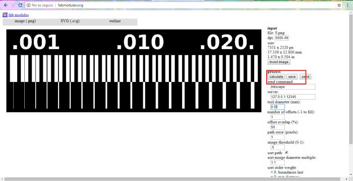
In order to carry out this process, we generate the process directly from the image, which you can download in the following link
DOWNLOAD FILES
After having the image we proceed to the machining processes.
As a first step in Fab modules to transform to SVG format. Once the format is chosen, we calculate and save the file.
Open the svg in Flat CAM and double click on the file to convert to G-code modify the specifications as you can see in the image, modifying the tool to use, speed of displacement and the depth that the z axis descends.
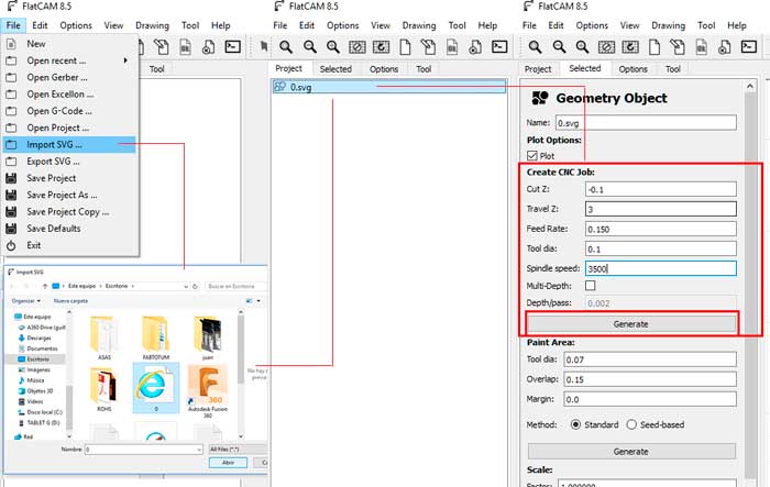
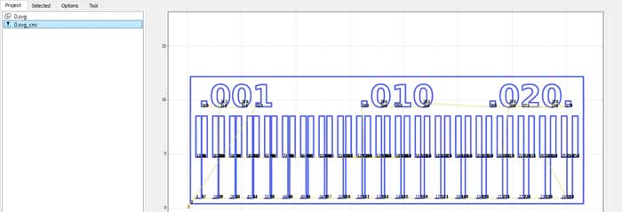
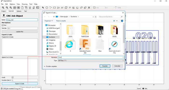
This gives us another file with which double clicking on it allows us to export the necessary G code to be able to mechanise our test.
Something very important is that when saving the file we must put the type of format in our case the "NC" format.
As to next step we proceed to add the file in the machine to machine. we use Fabtotum which uses Fab ui as a driver software, a very simple program to which you only load the file and calibrate the machine to machine.
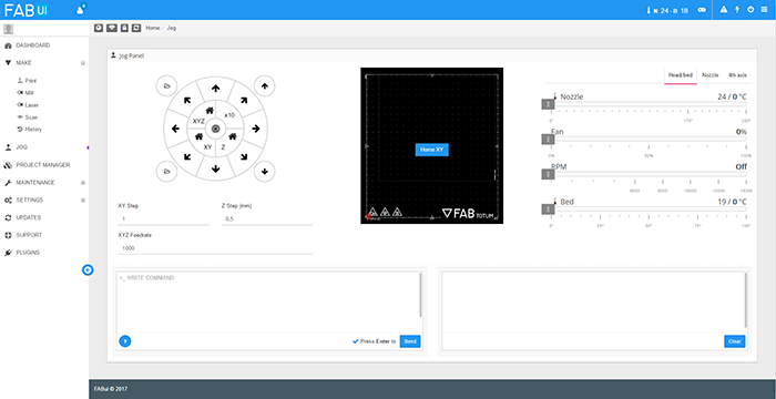
you can know more about the machine in the following link
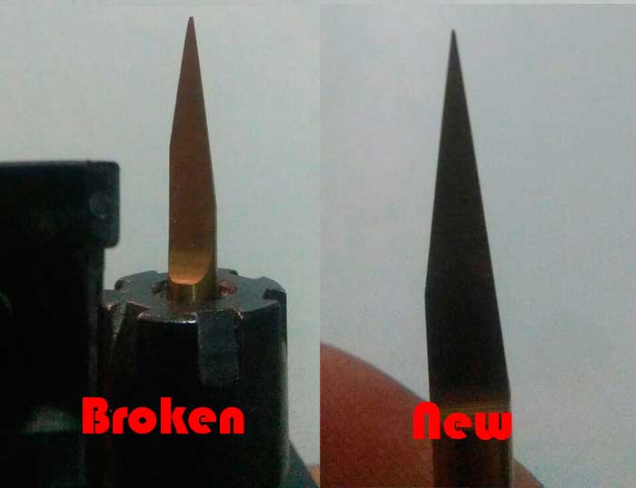
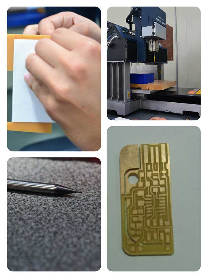
Once exported, machining the file was machined with a 10-degree milling cutter to 0.01mm when performing the first tests. We did not realize
that the milling cutter was broken, so it did not do a good job.
Here you can see the broken tool and a new one.
Then we can see the plates that were made with the broken mill since it could not get a good result in the finish.
In the following images we can see the change with the new mill. Once the problem was solved, we continued to calibrate the bed since it was level. to solve this simply calibrate can see in the following video.
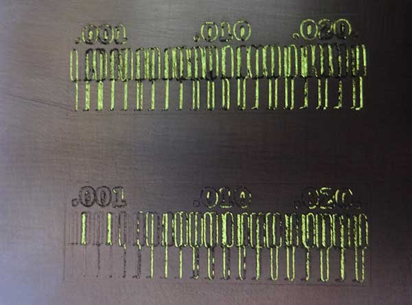
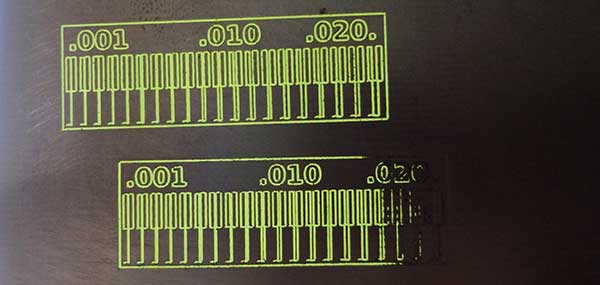
After the calibration process we generated the test and as you can see in the image we had a good result. In which we can see that we can not make tracks with a resolution of 0.001 but we have a good result from 0.01.
This practice seemed very important because with it we can calibrate our machine correctly and know the advantages and disadvantages of it and
its resolution and behavior in each of the tests required by this exercise.
As we can see in the image, the working field according to the resolution is 0.010mm onwards, obtaining an appropriate resolution for the
development of electronic circuits.
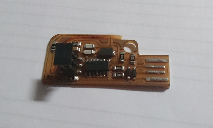
I select the Valentin board to make this assignment; this board is use as a programmer. At the end of the page, you can find the link for more information.
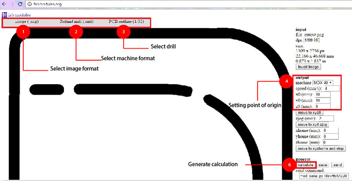
In the web page of fab module can modify the file to process in the machine. In the next image, you can see
all configuration and steps to make the image process.
Frist select the format and the image
Second select output format
Third select drill
Next Setting point origin
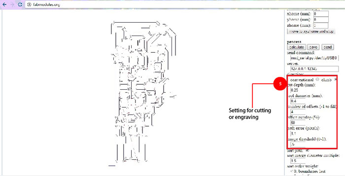
Next setting for cutting or engraving
To finish generate calculation
Before starting be sure you have the correct drill 1/64 (traces) or 1/32 (cut) and be sure that plaque
fixed to the machine.
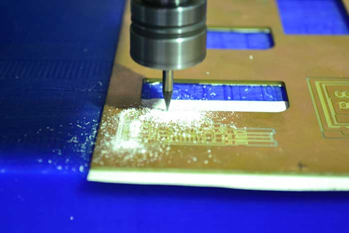
Once secured. We begin the configuration go the machine starting with placing the starting point of the machine in "X" and "Y" (x=0, y=0) and setting z with the sensor that is connected because can damage the sensor, before to start cutting, verify all the parameters be correct and press "cut" to proceed.

2 Res 0Ohm
1 Cap 0.1uf
1 Res 10kOhm
1 Cap 18pf
1 Osc 20MHZ
1 Res 499Ohm
1 Res 1kOhm
1 Res 100Ohm
1 Attiny 44A
1 Zener-dioder
1 Header 2x3
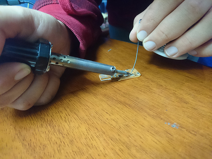
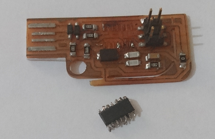
For the soldering process on this plate we first place the tin, taking care with the amount of tin so that it does not expand to other points that we do not need or that can create continuity.
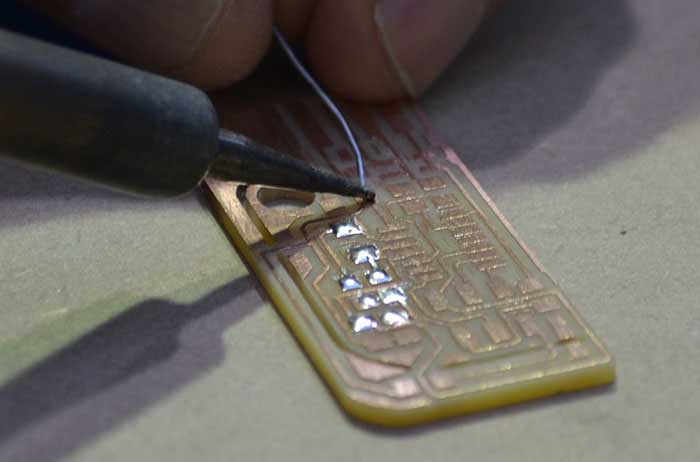
then we hold the components against the tin spots on the plate and proceed to reheat them so that they join.
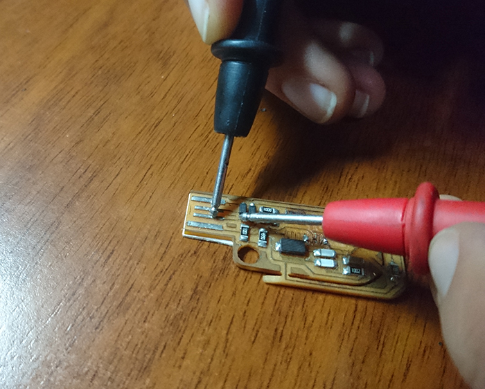
As a last step and to check that everything is correctly with the multimeter, check that it has continuity between tracks and not between spaces where they are not connected.
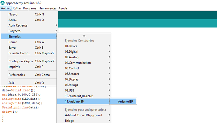
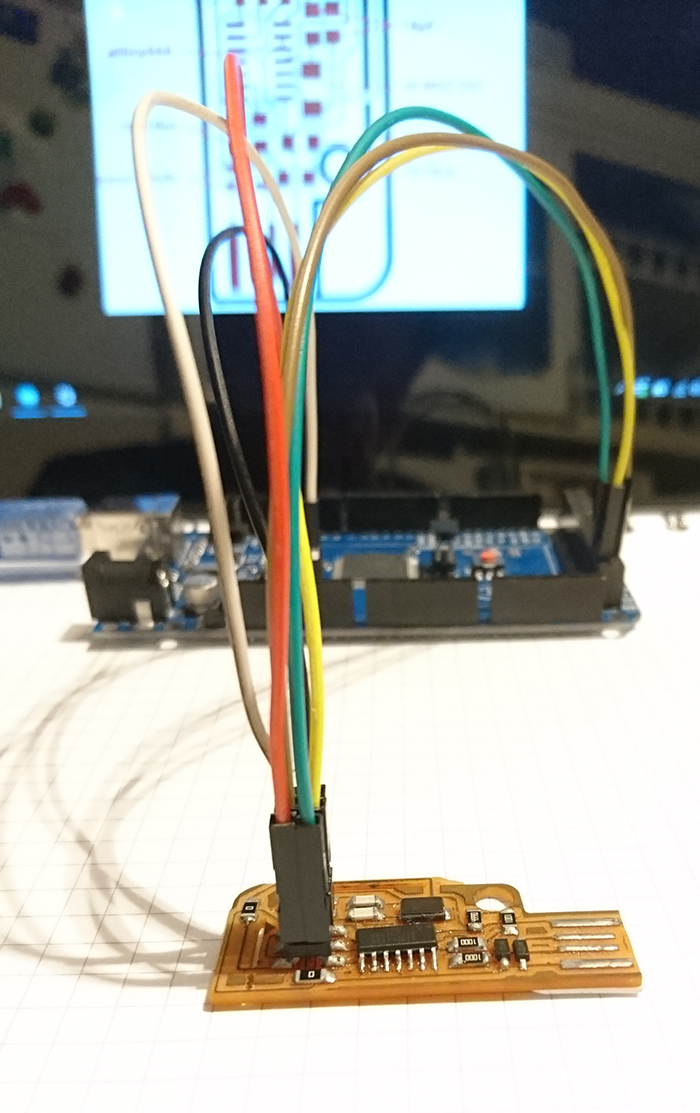
In order to program the board, you use a Mega Arduino which will be programmed as an ISP to select this library are chosen inside the library of examples as you can see in the image.
In order to program the board, you use a Mega Arduino which will be programmed as an ISP to select this library are chosen inside the library of examples as you can see in the image.
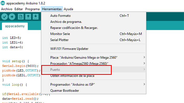
Download the following link in which we will find a software with which the file is loaded to the micro controller of the board.
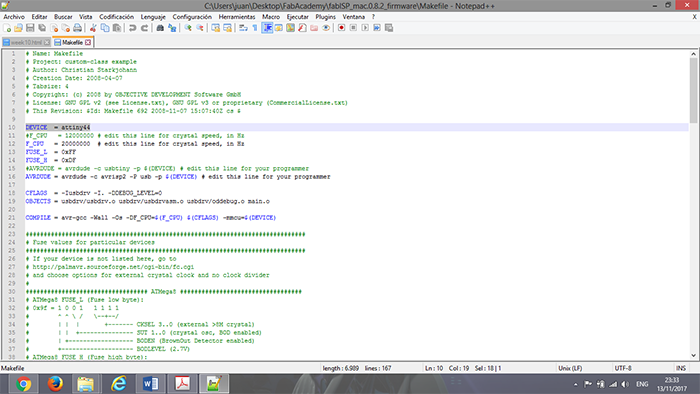
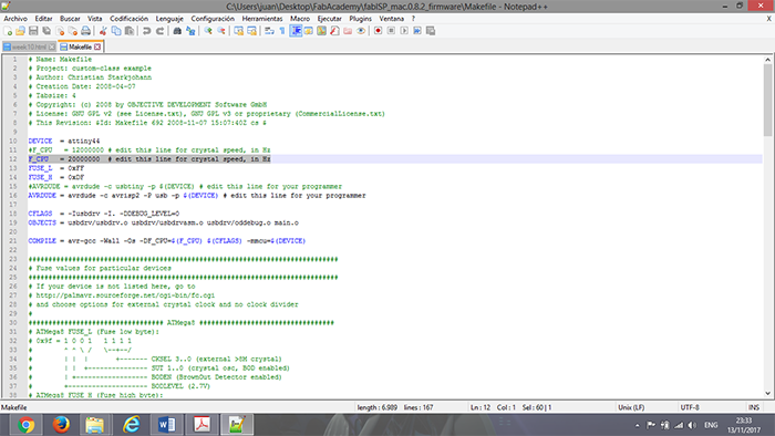
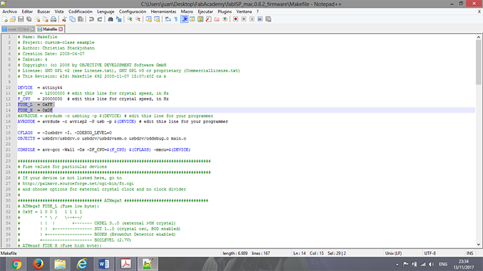
Open the file MAKE FILE with NOTEPAD ++ and edit the file.
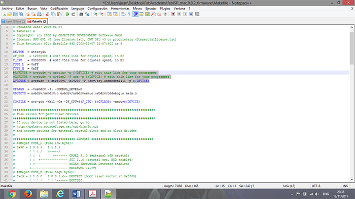
We installed the program CYGWIN with which we created a simulation window.
In the program, we enter until locating the folder in which the FRIMWARE was saved.
To be able to locate in the folder we enter CD CYGDRIVE and the next step is to locate us in the direction of the file
Following is cleaned the files that are already generated with the command
MAKE CLEAN
Then the hexadecimal file is generated with the command.
MAKE HEX
Next, we compile the fuses.
MAKE FUSE
Finally, we programmed, we uploaded the Arduino file to the plate
MAKE PROGRAM
I had two small mistakes in developing the assignment.
The first in the milling process, where some tracks were joined as can be seen in the following image. To solve with a blade the
affected areas are cut.
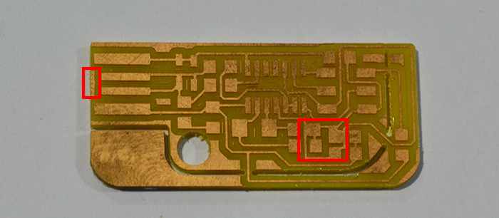
In addition, the second one found a damage on the microcontroller so it had to be replaced. In this way could be programmed without any problem.
I really enjoyed learning about this process because it is important for the development of my final project as it is one of
the main processes of electronic production and avoiding using polluting methods is very helpful.
In this assignent I learned a lot since my knowledge about electronics and programming was very little.
The mistakes I had helped me to deepen my learning in this area to be able to solve.

