Materials, tools and software
Programmer(Tools)
Circuit (Materials)
Arduino(Software)
 |
 |
 |
 |
|---|
Programmer(Tools)
Circuit (Materials)
Arduino(Software)
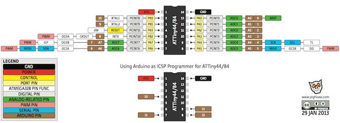
For this assingment we support ourselves from the microcontroller's datasheet to generate connections, programming and burning bootloaders.
The use of the pins is detailed below.
Pin 1 or Vcc is used to energize the board and perform its operation.
On pins 2 and 3 for the Crystal Oscillator.
Pin 4 Reset which goes to the pin and to burn bootloader.
Pin 5 for the button with which we will control the on or off of the led according to its programming.
Pin 6 the led is connected.
Pin 7 MOSI to burn bootloader.
Pin 8 MISO to burn bootloader.
Pin 9 SCK to burn bootloader.
Pin 14 GND.
ATTINY44A is a 8-bit AVR microcontroller with 4K bytes In-System Programmable Flash.
Voltage - Supply: 1.8 V ~ 5.5 V
Oscillator Type: Internal (128 kHz & 8 MHz) and External (20 MHz).
Port B is a 4-bit bi-directional I / O port with internal pull-up resistors, to use pin PB3 as an I / O pin, instead of RESET pin, program ('0') RSTDISBL fuse.
Reset input. A low level on this pin for longer than the minimum pulse length will generate a reset, shorter pulses are not guaranteed to generate a reset.
Port A is a 8-bit bi-directional I / O port with internal pull-up resistors as the in port B.
In the next link can see more information of datasheet
To experiment with other languages we use BASCOM - AVR is a software that uses basic language and transforms it into a program
which can run in AVR.
If you want to learn more about this program I have attached a link for a tutorial.
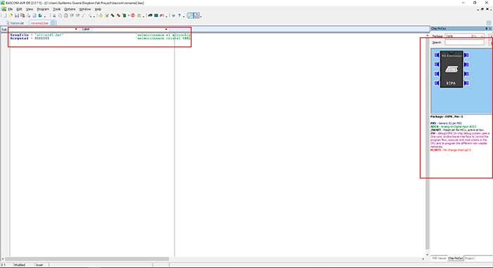
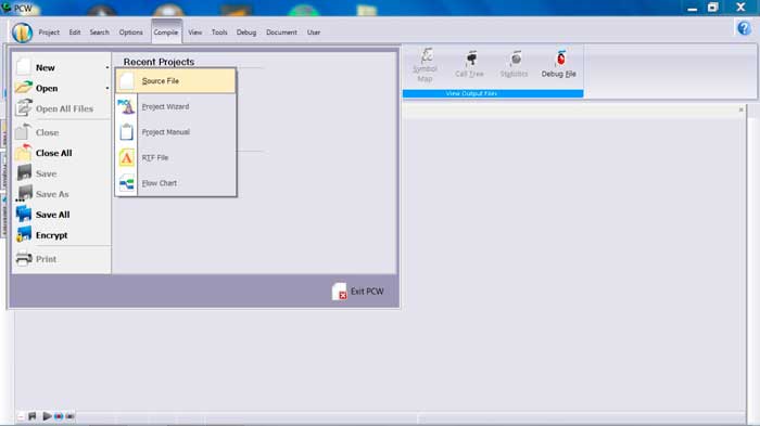
As a first step, we opened the program and created a new file by clicking on FILE and choosing NEW. this will create a new window for us.
Once the file is created, we start the programming. First of all, we must make the programming of the microcontroller and the crystal that
we are going to use. for this case we will use an attiny 45 with its internal crystal of 8 MHz. Once established this we enter and in the
right window we will see an image of the selected microcontroller. It also allows us to interact with the microcontroller showing its pins
by clicking on each one from them.
As next step we add the port and the pin to use.
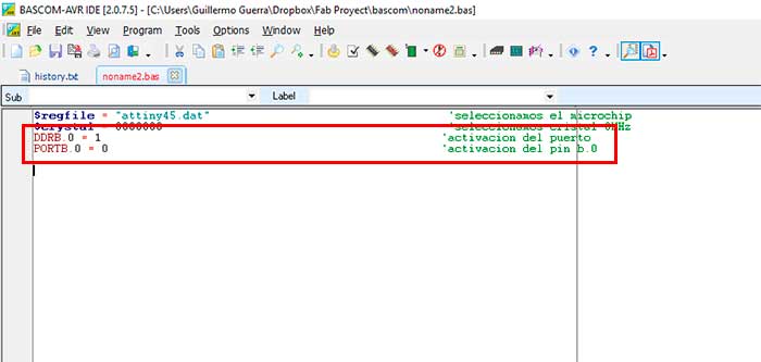
In this step we create a routine which will be repeated indefinitely, within this routine we will program the port to be activated and deactivated
by passing a second and this will repeat the routine again.
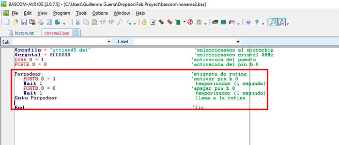
finally finished the programming compiled the program to check if everything is in order.
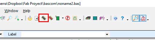
We saved the program to simulate in PROTEUS, a simulation software for electronic circuits.
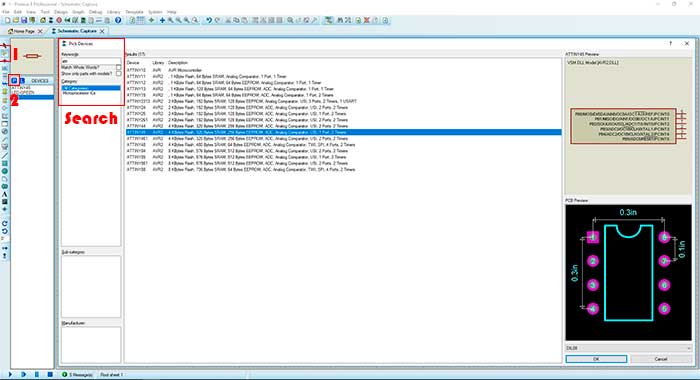
To simulate create a new file where we choose the first tool COMPONENT MODE in this tool we will select all the necessary components for the
development of our electronic circuit.
In the program they omit the VCC and GND pins so we have to choose the SUBCIRCUIT MODE tool in which we chose the GROUND port to be able to
connect the resistance.
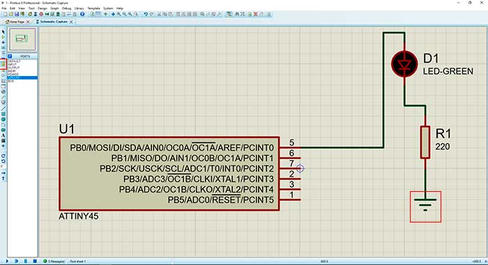
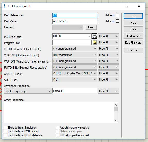
When we finish the previous steps we load the programming done in Bascom for it we give double left click in the microcontroller, in the PROGRAM
FILE window we load our programming in HEX format and in CKSEL FUSES we make sure that we place the same crystal of the programming and the other
windows as you can see in the image below.
As a last step we put play in the lower left corner to execute the simulation.
Within experimentation use PIC C COMPILER is an intelligent and highly optimized C compiler that contains standard C language operators and built-in library functions that are specific to PIC records.

In this software, once installed, we proceed with the creation of the new project in which we create a program in order to turn on and off for a certain time.
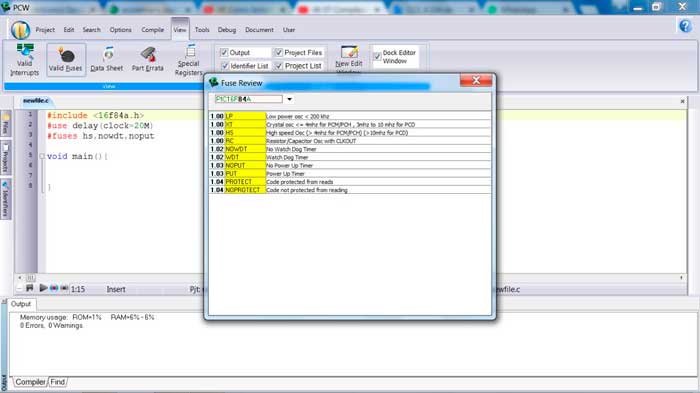
As a first step we declare the microcontroller, frequency and fuses. An option that is important to me, in the view window we find the tool "VALID FUSES" with which we verify that the description of the fuses is correct.
As explained above we will perform the programming to turn on and off a led for a defined time. The functions are commands which can be called
in the code according to our needs, with this we create a function which allows us to call the code created for the detailed action at the beginning.
Within the logic:
-We start lighting the pin in which we are going to program in this case the a0.
-As a next step we add a time of 500 ms.
-Then we proceed to turn off the same pin a0.
-With the same time.
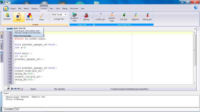
Once this is done, we carry out the compilation and the construction of the code made with the compilation serves to review some error in the program and when building it, it generates the "HEX" file.
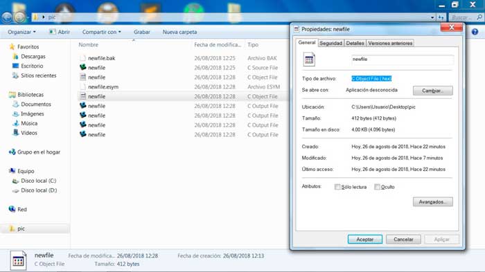
This format will serve us to export to the "PROTEUS" program in which we can simulate its operation
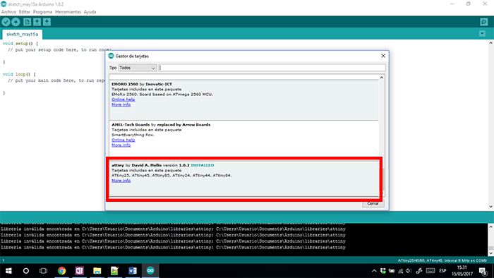
Next open Arduino software in the next direction Archive - preference, past this link "https://raw.githubusercontent.com/damellis/attiny/ide-1.6.x-boards-manager/package_damellis_attiny_index.json"
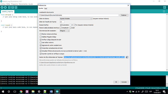
Then go to the next direction
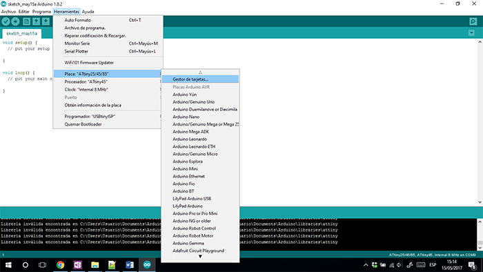
In addition, install the library of Attiny
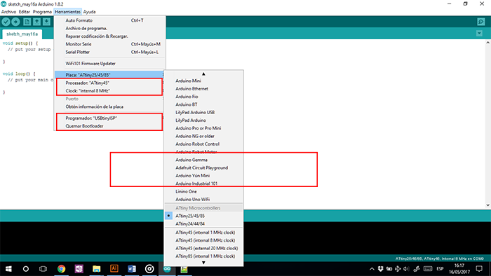
For make this. First select the microprocessor and is recommended work in 8 MHz, to check this
go to "Tools – Clock. In the same window select “USB tiny ISP" by way of programmer.
To end check in burn Bootloaders
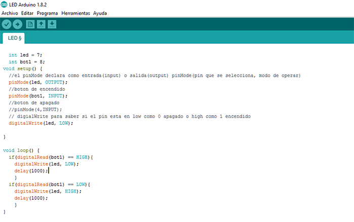
To programming, I know the logic of the program. In this I turn OFF a led with a button.
PSEUDOCODE:
-Bigin
--declarate variables
--configurate by outputs or inputs
--configurate digital ports
--If button = high then
--led = OFF
--else leb = ON
-End