ELECTRONIC DESIGN
In this week we learned about electronics, which includes the design of the schematic, the board routing and PCB making. For this purpose, I chose to use Autodesk Eagle Software since I was already familiar with some previous version. In Eagle we are able to design either the components, schematic and board. First need to download library from:
http://academy.cba.mit.edu/classes/electronics_design/index.html
go to -->Circuits-fab.lbr
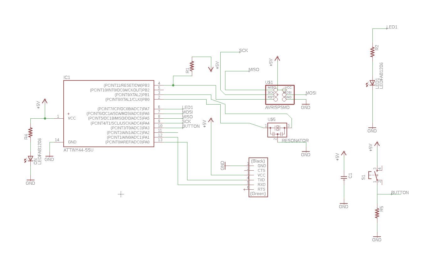
And then need to add Autodesk Eagle Software. This assignment was to redesign the “Hello Word Board”. The picture below shows the schematic that I redesigned. I added an LED as an indicator of the power supply, and one input switch and output led to test it.
The software I used.
• Software Eagle.
• Software FlatCam.
• Fablab Modules.
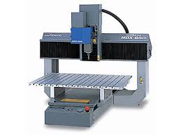
Milling machine I chose.
• Roland Mdx 540.
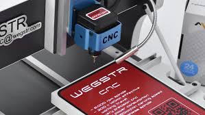
• Wegstr CNC.
On Eagle Software
PCB design in EAGLE is a two-step process. First you design your schematic, then you lay out a PCB based on that schematic. EAGLE’s board and schematic editors work hand-in-hand.
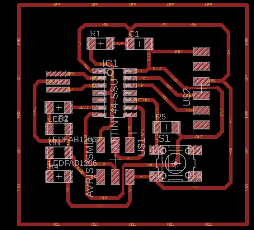
The picture below shows the board as seen in Eagle, I made the traces and it fit perfectly, the traces were too small.
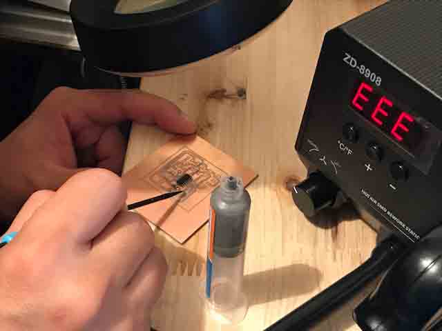
In my case used two different machines to make the board.
The principal problem when I made the electronics board are the trace, the width trace in my opynion is most importand think when I desing the board. Thr presiscion to mill need a good development on Eagle. The width trace are 0.4mm.
On this board I used one Imput (botton) and one output (led). The input is was connected on analog pin 3 with pull down resistor 1k ohm and the led to pin 7 with 1k ohm . The programer was used Atmel AVRISP MKII with arduino IDE 1.6.4.
Milling Machine and Made Board
Schematic
Board
Gcode
Blink Arduino code
Button Arduino code