OUTPUT DEVICE
Week 11
ASSIGNMENTAdd an output device to a microcontroller board you've designed and program it to do something
SOFTWARE USED
- Arduino IDE
- Kicad
HARDWARE USED
- Board Fabacademy 2017
- 5V Dc motor
- Potentiometer
- L 298N H bridge
- 12 volt alim
Board 2017 KiCad
Potentiometer and motor
LEARNING EXPERIENCE
For this week, I decided to control a DC motor. I had a motor at fablab that gave us a model maker so we could test it.
I learned how a DC motor works, how to control it with Pulse With Modulation and a potentiometer.
I used my fabacademy 2017 board for this assignment.
BOARD FROM FABACADEMY 2017
This board was done last year for my first test of the final project.
It was designed to give help maintain a temperature in an isolated haybox for a street food device on a trailer bike.
I will briefly describe the workflow, it is better described in homemade sashakit board and in the final project board...
It is a very simple board based on an AT MEGA 328 with:
- Ftdi 6 pin connection, to communicate and program the board.
- 2 connectors with analogic and digital pin connnected
- A 16 Mhertz Crystal with 2 capacitors.
- Reset, led and resistance.
I chose the components and connect them.
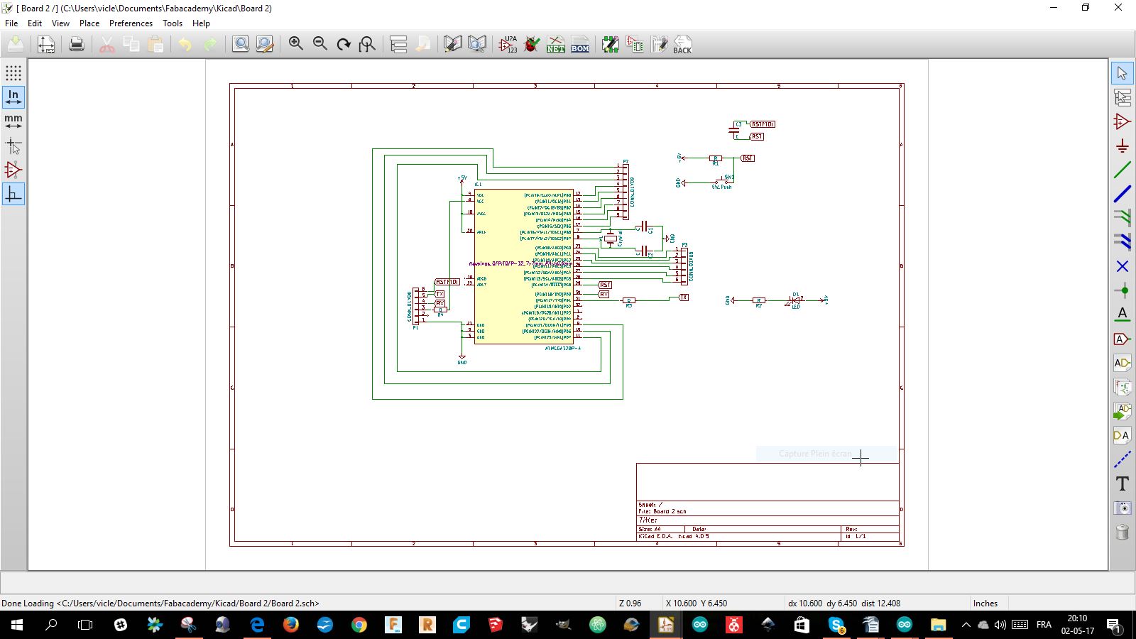
I annotate the components and make the component list.
I associate the components and the footprints,
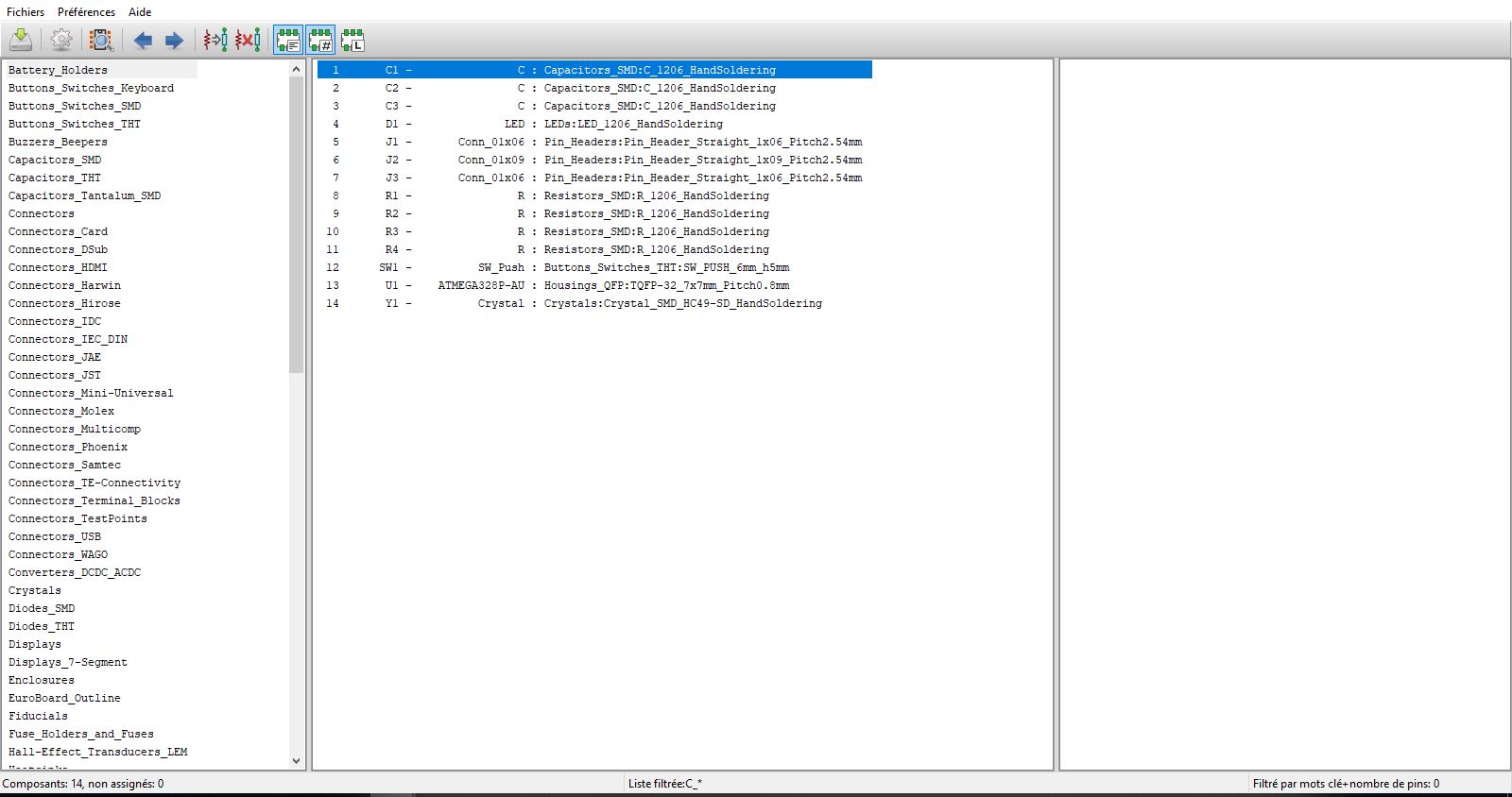
And generated the NETLIST
Opened the PCB file and read the NETLIST
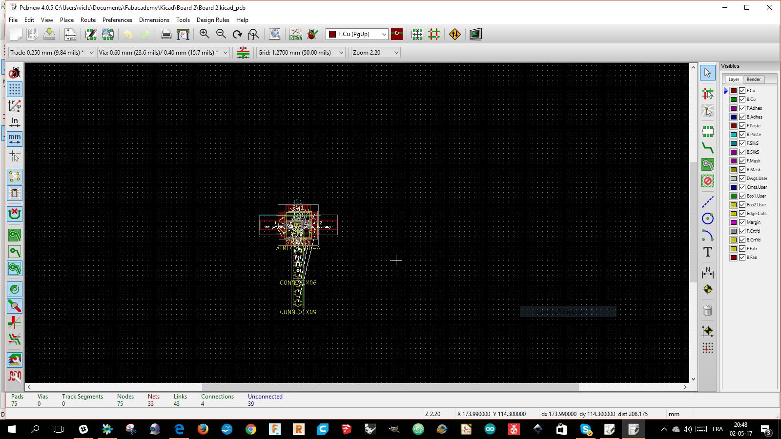
Moved the components to place them in a way. to have the less crossing possible.
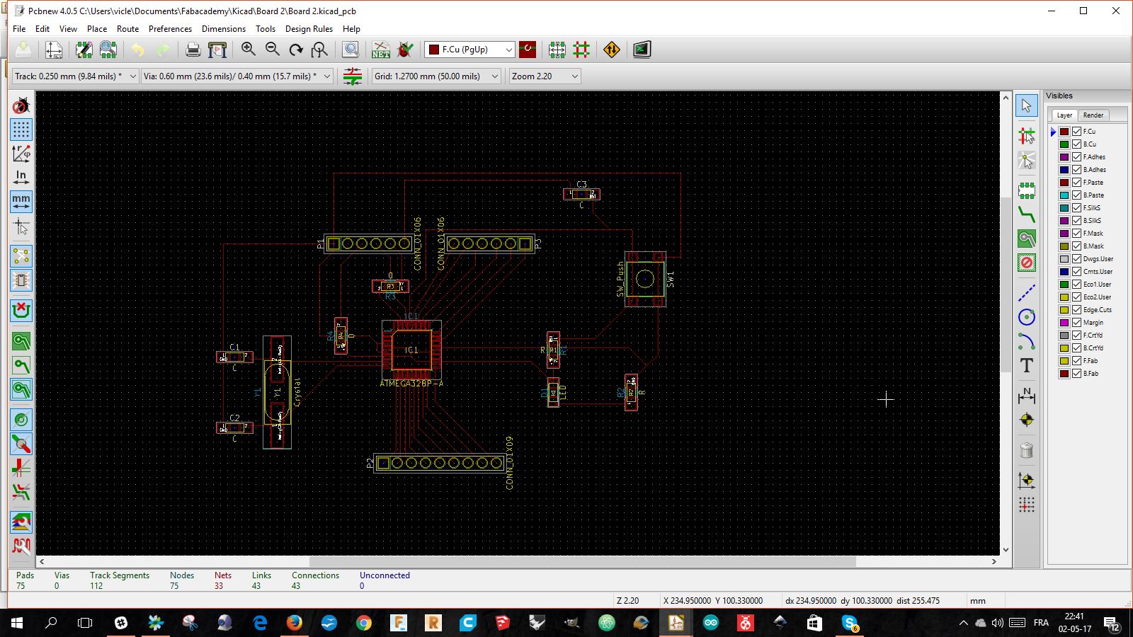
Finalising the connections
I printed in PDF the circuit using the plot function
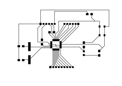
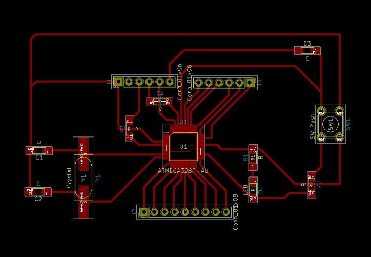
I used the same chemical etching technique use in the electronic production week,
see process in the week electronic production
The first question was: How to control the rotation speed of the motor?
For that, we will work with Pulse With Modulation.
The principle is this:
We will send 5V power, from the microcontroller, with a certain frequency that we will modulate.
The tension modulated in this way will have an average value determined by the frequency of the wave that goes from 0 to 1. (0 to 5 volts).
The following diagram shows the ratio between the percentage and the frequency of the current that is sent.

POTENTIOMETER AND PWM
We will use a potentiometer to give this value.
A potentiometer is a variable resistor using a slider or rotary knob to modulate its resistance.
The value of the resistance can be read on the ADC pin of the microcontroller.

If we look at the data sheet from the AT Mega 328,
we can see that the ADC pins are in 10 bits : 210 (1024 divisions) and the digital pins are in 8 bits: 28(256 divisions).
The microcontroller will read a value from 0 to 1023 determined by the resistance of the potentiometer.
This resistance will vary by turning the knob.
So we will use the MAP function which will turn the increments of the potentiometer(1024) into PWM value(256) to send them to H bridge.
See map function in the code below.
map(value, fromLow, fromHigh, toLow, toHigh)
100 pc = the potentiometer does not resist and therefore the motor receives all the current.
50 pc = the potentiometer withstands half of its resistance and the microcontroller sends current half the time.
0 pc = the potentiometer resists and the motor does not receive power.
That is the way we will modulate the speed of the motor.
H BRIDGE
The motor is a 12V DC motor..
We will use an H bridge that will allow to control it.
We will connect the pins of my card as follows:
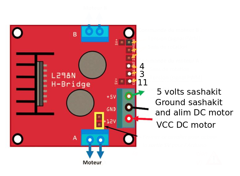
To control the H bridge we need two things:
The direction of the current
The value of the PWM
For this we will connect pin 3 and pin 4 output
and we will give them a value (3, HIGH and 4, LOW) which will give the direction of the flow of current.
We are going to pin the pin 11 of the board that works in PWM.
It's not over ...
The potentiometer will be connected to the A3, an analog pin.
Code


 /*

Victor Levy, Fabacademy 2018, week 11, output device
Change speed of a 12v motor with PWM and a potentiometer

 */

int analogPin = 3;     // potentiometer wiper (middle terminal) connected to analog pin 3
                       // outside leads to ground and +5V
int val = 0;           // variable to store the value read

void setup()
{
  Serial.begin(9600);              //  setup serial monitor
  pinMode(11,OUTPUT);
  pinMode(3,OUTPUT);
  pinMode(4,OUTPUT);
  digitalWrite(3,HIGH);
  digitalWrite(4,LOW);
}


void loop()
{
  val = analogRead(analogPin);     // read the input pin
  Serial.println(val);             // to write on the computer serial monitor the value of the potentiometer
  val = map(val, 0, 1023, 0, 255); // map the value to transform the value of the potentiometer to PWM
  analogWrite(11, val);           // gives the value to the h bridge