interface & application programming
april 18 - april 25
● The goal for this week's assignment is to write an application that interfaces with an input or output device that we made
● Neil gave us a really informative lecture by showing an overview of all the different languages, device interfaces, data interfaces, user interfaces, graphics, softwares and applications which could help us write/create a graphic user interface (GUI) that interfaces with a PCB we made either from input or output devices week.
● Hashem made us introduce to the MIT App inventor during the session he conducted, he had worked on the same for his Fab Academy 2017 final project. It was nice how he explained the working of the same which was basically based on blocks and quite easy for a first times to understand.
getting started
● I had never worked on any of the topics before Fab Academy so it was really good to know all of the diversified tools and languages which help me create a GUI that interfaces with my board from the output devices week.● I planned on using the RGB LED board which I made for the assignment of output devices (Week 12), for this week's GUI assignment. And for programming the same I shall use the FabISP that I made in Week 04.
● I decided to work on Processing, which is an open source free software to download. It is a flexible software sketchbook and a language how to code within the context of the visual arts and visual literacy within technology. Wendy recommended me to go through a series of Tutorial videos by Dan, who very interactively explains everything about processing starting from the introduction to much more advanced practices of the same.
● I invested good amount of time and effort getting to know more about it by going through the tutorials and some previous year's students as well. One thing I found interesting was Processing was more or less similar to Arduino in terms of the javascript or the sketch that we create in the IDE software.
● I realized that writing a the code from scratch in processing would be a real strugle for me and as prof. Neil say's, stand on the shoulders of giant. So, I decided to research a bit more about what interesting GUI previous year students created using Processing for RGB LED.
● I found a rather interesting page of Israa Rabbaa, who is actually a student of Fab Academy 2018 at Fab Lab Irbid. She has documented really well and I genuinely appreciate her work which helped understanding processing and arduino for this particular assignment.
● She operated the RGB LED by creating a GUI on processing which had four buttons to operate the LED by displaying basic colors such as Red, Blue, Green, Random and an OFF Button to turn off the LED. It was a rather simple code to understand because she had explained it nicely as well.
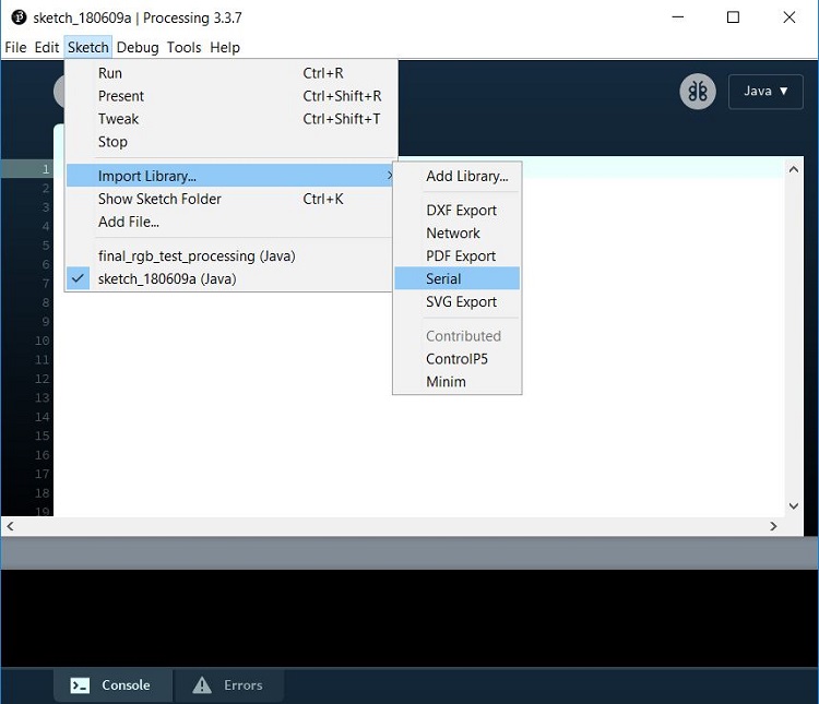
● It was essential to import the serial library in processing to be able to connect through Arduino serial port, this is a very important step to start with.
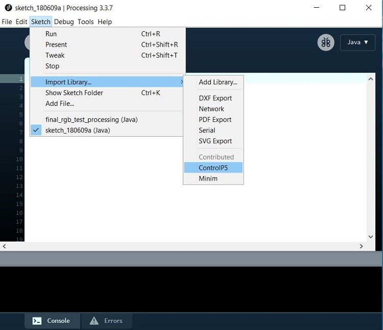
● In order to create the buttons she instructed to download, unzip and a controlP5 library into processing from this LINK.
● controlP5 is a library written by Andreas Schlegel for the programming environment processing Controllers to build a graphical user interface on top of your processing sketch include Sliders, Buttons, Toggles, Knobs, Textfields, RadioButtons, Checkboxes amongst others and can be easily added to a processing sketch. They can be arranged in separate control PGraphics contexts, and can be organized in tabs or groups.
● The library has to be copied in the libraries folder in processing download location. Following these steps the library will appear in the processing software as shown below.
● So, the first step for me was to test the very same code on the board created by me and see if it worked. And it did work very well, which gave me a confidence booster that I could definitely play around with her code in Processing and also in Arduino to add more colors, changing the background color and size of the display screen.
● Then moving on, it was my turn now to add more color options with button in the original code.
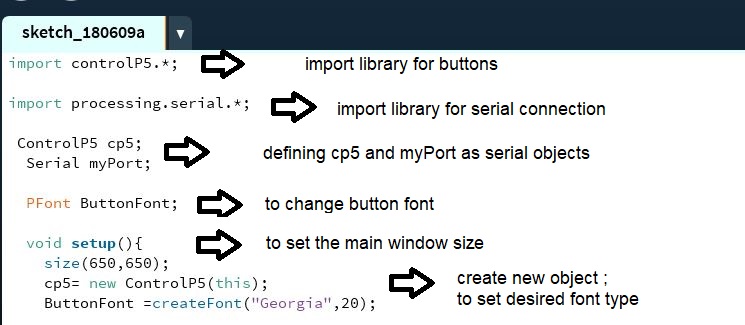
● In the following series of images, I have tried my best to explain all the functions used in creating the GUI using processing.
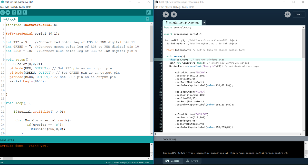
● Starting with adding the libraries
● Defining objects for controlP5 and serial myPort
● Defining button font for all buttons
● Void setup for the main display window of the GUI with size command, to create new object with desired font type and size.
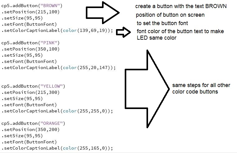
● Creating buttons for each new color I added such Brown, Pink, Yellow and Orange along with retaining the colors from before.
● Setting the positions for button, button font and the most important of all the color codes for respective color, also displayed as caption.
● Repeating the same code for all the colors.
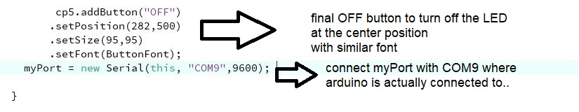
● Following the same process for OFF button. ● Allowing the connection from myPort with COM9 where my Arduino was actually connected to my FabISP during the programming.
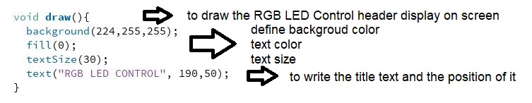
● Next step, to give a header name for the GUI as RGB LED Control on display screen with background color, text color and size and position of the content.
● Moving on to the most important part of the code to receive the data.
● defining function command myPort.write for each of the Color button, that once pressed, send the particular alphabet to Arduino, when Arduino receive then that particular color will be displayed on the LED and follow the same steps for all the color with different alphabets.

● Following the same command for OFF button as well.

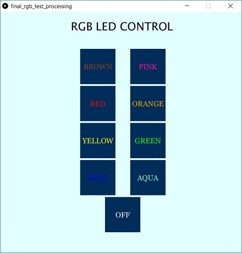
final display screen
● Download the modified Procsessing code for GUI HERE
processing code (modified)
● I also modified the Arduino code for the same, as explained below.
- Include SoftwareSerial library for communication
- Define integer for respective LED color.
- Setup respective pins as output
- Serial begin communication at 9600 bits per second
- Loop routine, send data when received..
- Read characters from incoming serial data for each color.
- Defining integers, setting value and setting brightness for Red, Blue and Green LEDs.
● Download the modified Arduino code for GUI HERE
arduino code (modified)
successfully uploaded the codes
check out the gui video for
rgb led control
learning outcomes
● This was one of those week's which shall help me great deal in future, even after the Fab Academy. I learned a lot through processing, how to add libraries, create buttons, font, color for the same, setup serial port for connections and sending characters to operate the LED's for respective colors.● Also the ability to connect Arduino and Processing to achieve GUI that has been created. I wish to work on similar projects in near future.
● Very new and fresh experience for me and I look forward to upcoming weeks.