computer controlled cutting
feb 07 - feb 14
● The task for this week was to learn and implementat computer cutting cutting tools and techniques with the help of laser cutter and vinyl cutter machines. The goal was to characterize the machine, try different materials and apply different process parameters resulting to diversified outputs for practical learning.
● My responsibility was to demonstrate and describe parametric 2D model design along with identifying, explaining the process involved. The idea was to develop, evaluate and construct final prototype. One of the group project was to work on the laser machine to identify the kerf of the cut so as to construct a better fitting press-kit for the coming week.
● Learning the tools for parametric design and techniques for the same helped me get a good overview on how to go about creating various structures and getting them on the laser cutter. To know about the usability of the machine and the safety aspects plays an integral role in future. It's been a great week in terms knowledge I gained in this week.
● Group Assignment: LINK for Computer Controlled Cutting.
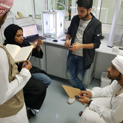
It was a enjoyable experience to work in a group in order to characterize the machine and identify the kerf of a cut for the laser cutter. We learned a lot in this assignment due to the chance provided on working with each other, also complement each others skills, appreciating the work done by each and everyone and embracing the fun filled moments.
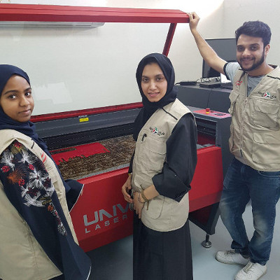
Happy times :)
getting started
● Computer-Controlled Laser Cutting
MACHINE:
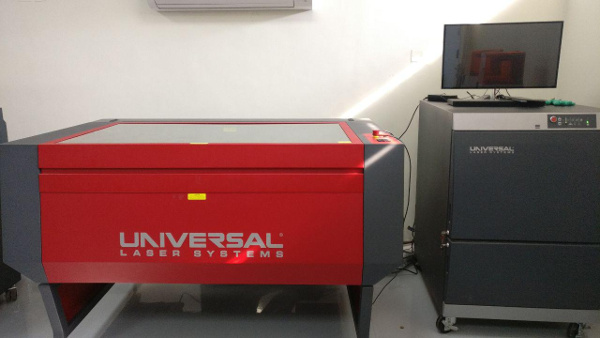
75W CO2 Laser Machine from Universal System.
MATERIAL:
Cardboard 6.5mm thickness
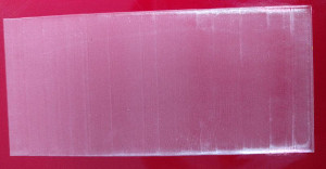
Transparent Acrylic 5.1mm thickness
Red Acrylic 5.1mm thickness
Software:
CorelDraw
Learning and testing the machine
Process: We start with simple shapes (circle with 30x30, triangle with 100x50) to test.
In the preference there are setting that can control the power, speed, PPI and flow rate for air.
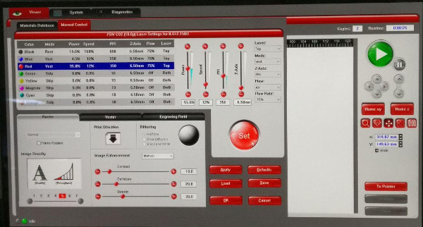
We skip all the color except black, blue and red. Black refers to raster engraving strokes, fills also Blue refers to vector engraving / scoring Red refer to laser cutting lines.
We can adjust the location of the origin for the laser. We place the material inside the machine.
We did five tests for cardboard, each time we change the setting so we can see the different in output. Six tests for transparent acrylic and one for red acrylic.
| Material | Thickness | Power(%) | Speed(%) | PPI |
|---|---|---|---|---|
| CardBoard | 6.5 mm | 62, 70, 80, 90, 95, 100 | 11, 12 | 250, 300, 350 |
| Transparent Acrylic | 5.1 mm | 35 | 40, 50 | 1000 |
| Red Acrylic | 3.4 mm | 65, 70, 75, 85, 100 | 11, 9, 7, 5, 4 | 1000 |
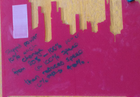
● Variation of the laser engraving witnessed on red acrylic material.
● Attempted to try diversifies setting parameters while the machine was in operation to compare variable power from 20 to 100 in 5 steps(10% increase and decrease every time) and speed from 100 to 40. Great experiment to witness the different layers, expressing the change in power and speed during the laser operation.
Parametric Press-fit kit assignment
● This particular week, I faced a lot of trouble get going in terms of creating a parametric press fit model for my assignment, after much needed practice on Fusion 360, it is quite less challenging for me to carry out the same. I was slow to grasp this week's assignment and gradually I did complete it.
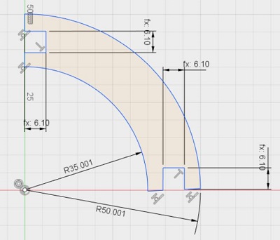
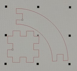
● Steps for creating a parametric design on fusion for Press Fit kit on Fusion 360. The below image shows the steps how I created one part of the press fit kit (hand) made out of a circle with the center line modified as the construction line and then proceeding to create two offset lines for the slot needed for the press fit. The significance of the construction line and the offset is that if we change the parametric dimension for the slot, it still will be in the center of the part. Then the two offset line which equally distanced from the center line can be turned into a non-construction line in to a normal line of the design.
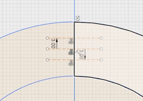
● The hand is one of the components of the design and the slot size is based on the parametric function in Fusion software. Parametric modification tools helps in a lot of ways, the slot size can be adjusted as per the material and product size and once the dimension is edited, all the slots will change accordingly as per their link to the function.
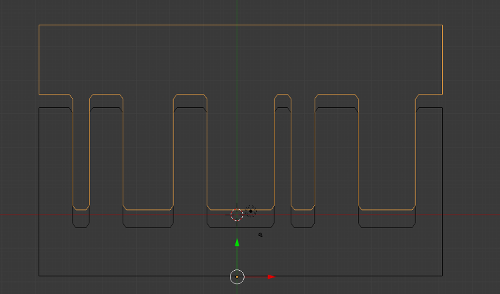
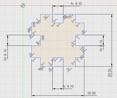
● The below image shows the second component of the kit in which the hand will fit and we have multiple ways to assemble the same. It is a very basic design in terms of the complexity but I learned a lot in terms of designing on fusion and enabling the parametric function on the modify tab in the software. The image also shows the slots have been linked to a certain parametric dimension and can be modified later which in turn will result in change on dimension of all the slots.
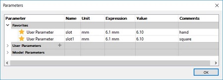
● The below image shows the all the dimensions for both sketches of the product and the different user and model parameters.
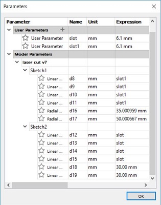
● The below image shows the user parameters in which I have specified a certain slot dimension as per the cardboard material thickness
● The below image shows the final parametric components on Fusion 360 which can be saved respectively in two files in the form of .dxf format.
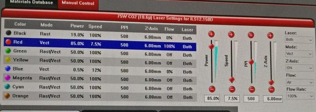
● Then after exporting the files from Corel Draw and changing the color to red in order to proceed with the vector cut on the Laser Cutter. The process parameters in the software for the Laser Cutter shows the power set at 85%, speed at 7.5% and Pixel per Inch (PPI) at 500. Usually the PPI for 6mm cardboard is supposed to be at 200 PPI which are enough pulses per inch for that particular material and thickness. The settings had changes overtime so due to which I did not realize the same. 500 PPI is for acrylic material. I'll make sure I don't commit to the same mistake in future.
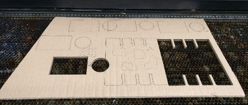
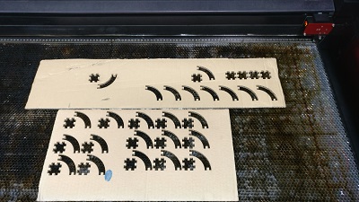
● The below image shows the placement of the parts for the cut out on the cardboard with 6.15mm varied thickness.
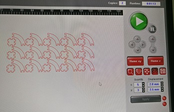
● The below image shows the cut out part on the laser cutter bed and the economical space saving by me so that I can use the most of it by placing it accordingly which in itself looks a rather impressive cut out design on the board... LOL
After some tests
&
editing the parameters a couple of times,
I finally achieved the tight fitting press-fit kit :)
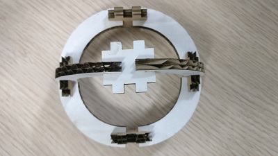
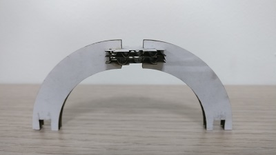
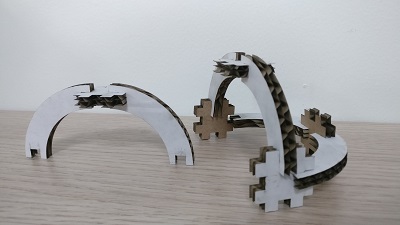
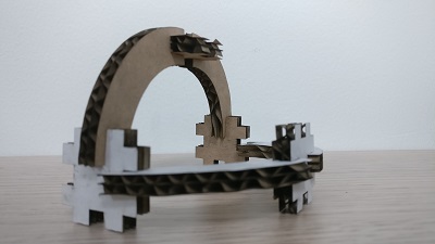
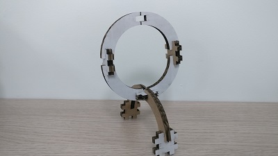
● A dozen of images below showcases how perfectly the parts fit into each other, which makes me quite happy in terms of accurate designing, editing the parameters at a rapid pace and using the laser cutter flawlessly even when there was very few people around me in the entire lab with some uplifting music in the background. Real boost to my confidence and a great deal of motivation to move ahead to the next challenge with a wide smile.
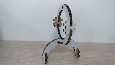
The following images show the various ways to assemble the kit.
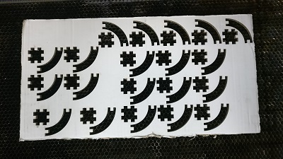
also got a really interestingly colored board,
one side white and the other brown
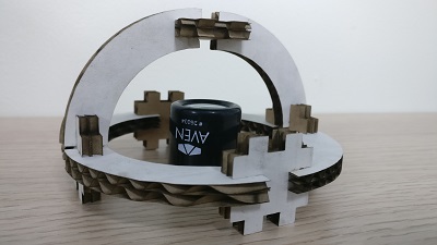
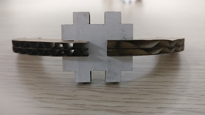
...and more playing around
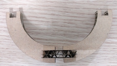
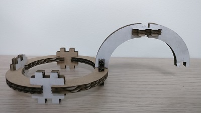
Just look at that,
destined to fit there.
do check out the following linked page where I used the laser cutter again:
● Visit WEEK 08 to have a look at the test cut I carried out on laser cutter.● Also visit WEEK 15 to have a look at the Mechanical Design week test, done by me.
● Computer Controlled Vinyl Cutting
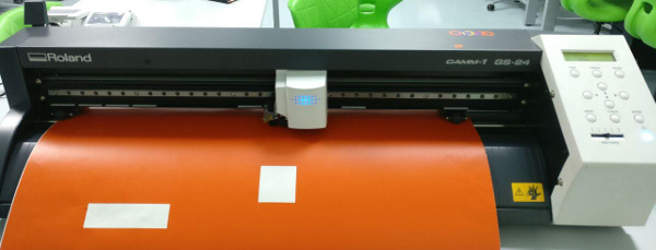
MACHINE: Roland GS 240
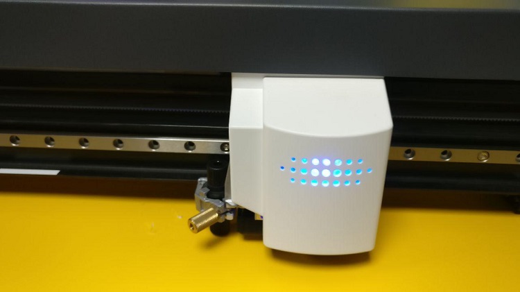
● A very efficient machine in terms of precision and accuracy, it's less challenging and quite productive in terms of the performance so far. Will be doing a lot of more stuff in the coming weeks on this particular machine. It works as a printer output once connected via usb on your machine and we used corel draw for cutting our designs stickers in the form of some logos and text. Below image shows the display screen provided on the machine to work on the same.
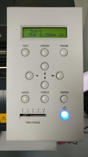
● The above image shows the display screen for the vinyl cutter, which presents the different parameters as per option selected using the buttons on below the screen.
● It helps you set the origin of the cutting head, also guides moving the vinyl in forward and backward direction.
● Displays the amount of force to be applied as per the material selected by the user and the length, width of the vinyl as the well.
● That's the sticker cut out from the vinyl cutter as a test we did couple of weeks earlier. I used a lot of Corel Draw in this week for vinyl cutter as well as the laser cutter. It was new for me but it is a user friendly software, quite intuitive and great workflow to get things done. Also I used inkscape for couple of things, I'll be sharing the images soon. I will be using the vinyl cutter the coming days to try different designs.
The Dali Mask
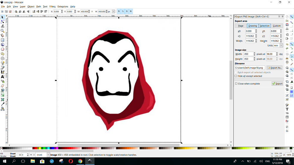
● So, I decided to make the Dali mask based on the famous artist Salvador Dali from a popular tv series of Netflix, I just wanted to try and see the outcome of the same. So I downloaded the jpg of the mask from google and started the process in Inkscape. The below image shows the mask.
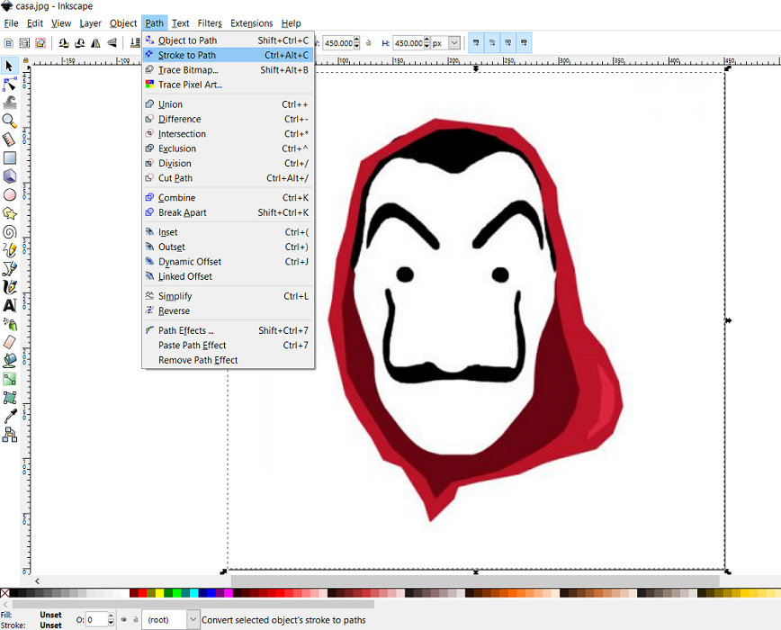
● To start with, I selected the design and used the tool of path and chose stroke to path to convert the strokes into a path and then move on to the next step..
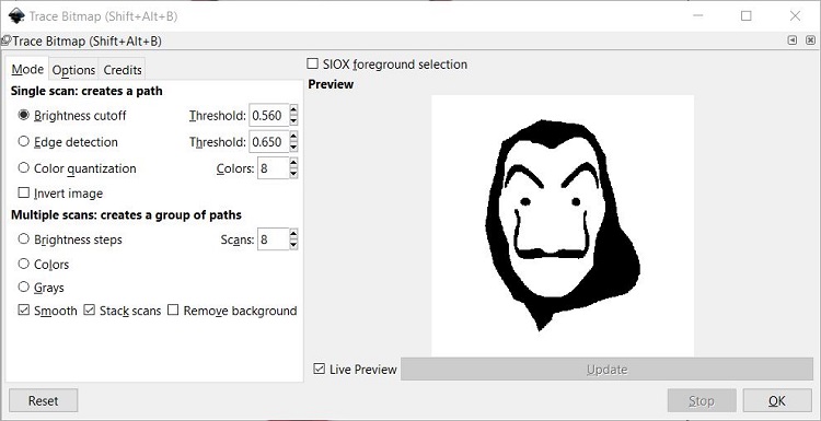
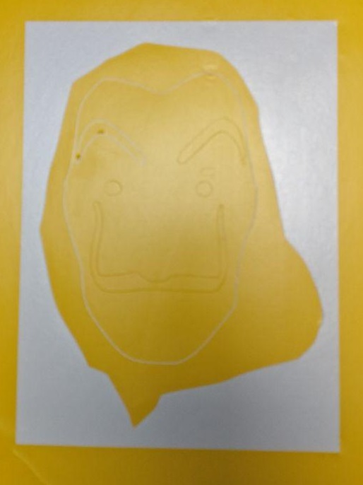
● Then I chose the option of tracing bitmap from the path tool and selecting the brightness cut-off option to get the best result of the design. This will change it into vector design.
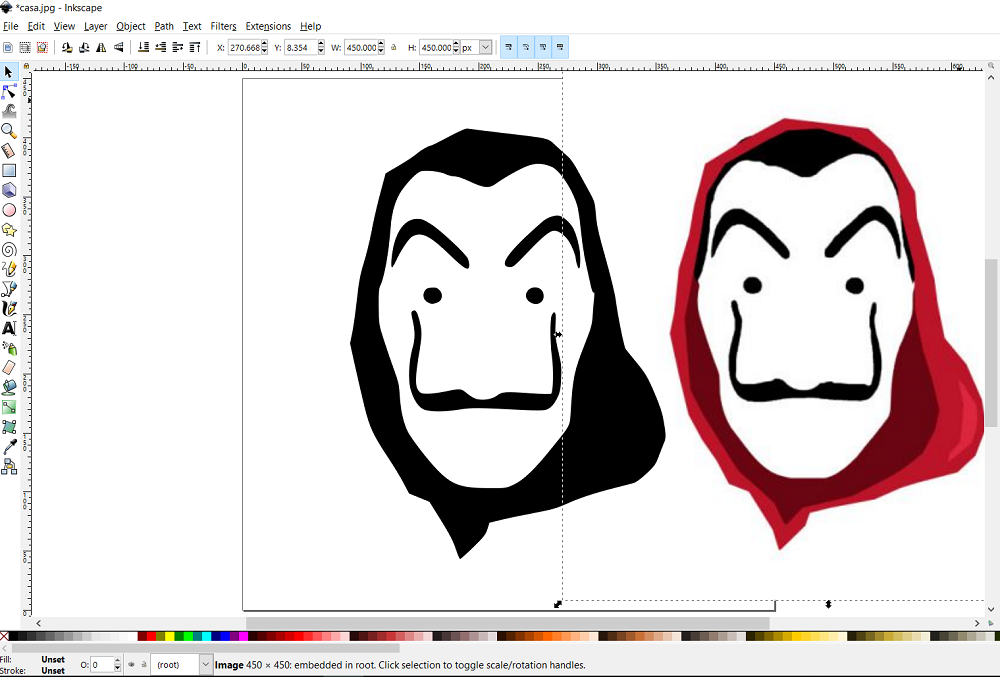
● You can see the new traced design compared to the original one, I deleted the original design and the new traced design does not contain any pixel.
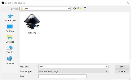
● Then I save the design in the form of .svg from inkscape.
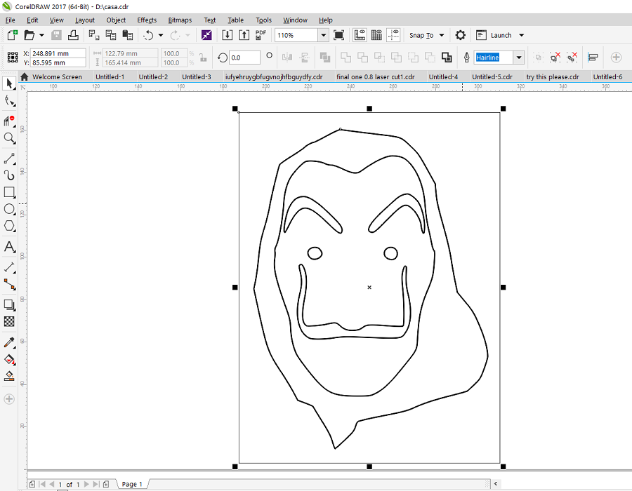
● Then I imported the .svg in Corel Draw as, I will be using the vinyl cutter with the help of corel and cut my design. The only modification I did in Corel was change the line to Hairline size for cutting process.
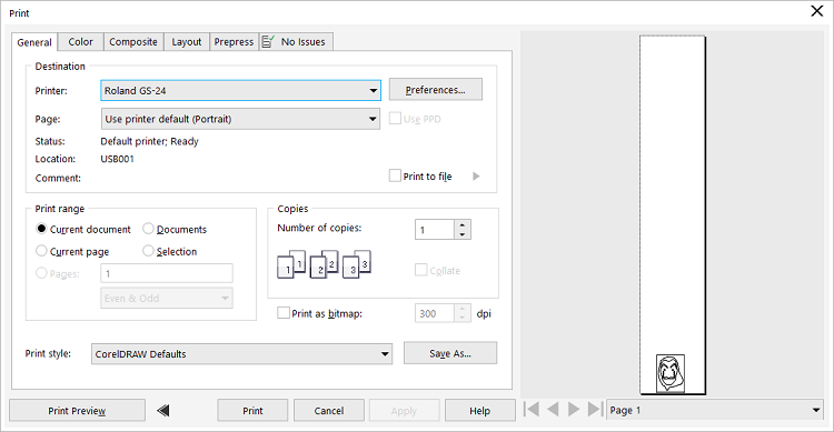
● Then moving on to print setup, we check the machine Roland GS-24 has been connected and we select the preferences option.
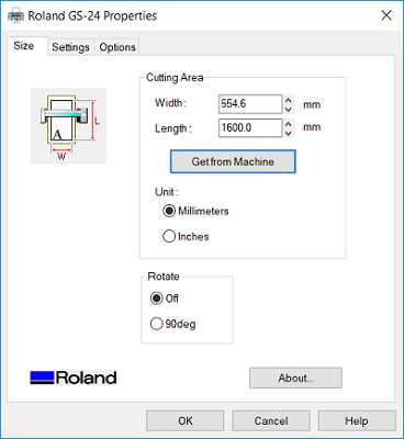
● In this window, we can get the size of the vinyl roll from the machine, also change the settings from this window as well. This is quite an helpful tool to understand the size, setting, other options and placement of our design.
● Moving on, I start the print/ cutting process with the help of the machine. The below image shows the process parameters selected for cutting. The force at 7 gf and speed at 5 cm/s.
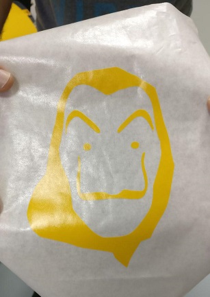
● That is quite a neat cut and as per my design a cut out the vinyl from the outer part of the design which is not needed.
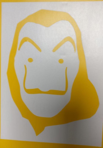
● Also after getting rid of the internal face of the mask, I get the final design ready to be transferred to the masking roller.
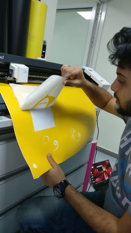
● I use the roller, cut some material for my use and slowly start sticking it above the design to make sure the design sticks to the roller.
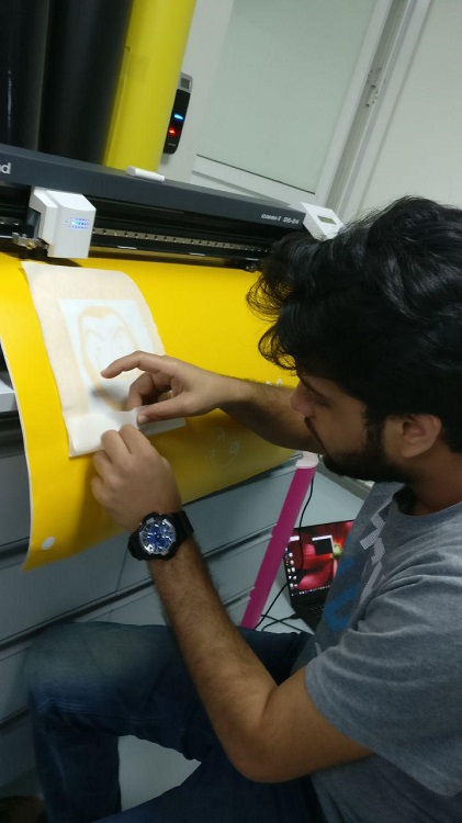
● It was quite a satisfying progress so far.
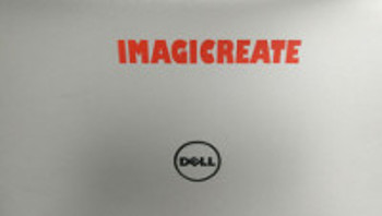
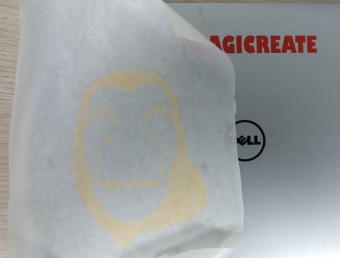
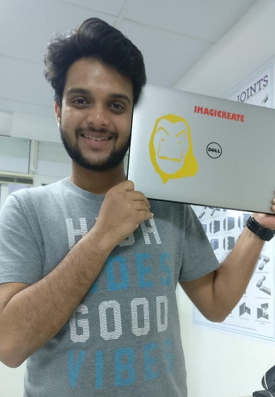
● Here is it, next step was to stick the mask sticker on my laptop.
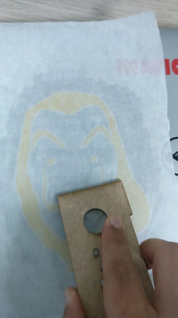
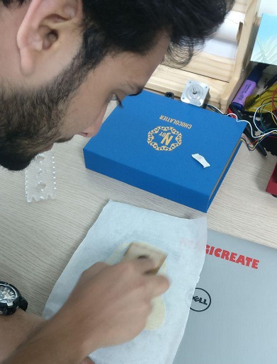
● So to do the same, I carefully stick and use a hard, flat material to make sure its stuck properly and to get rid of bubble formed.
● I follow the process for the entire design from all sides to make sure the same.
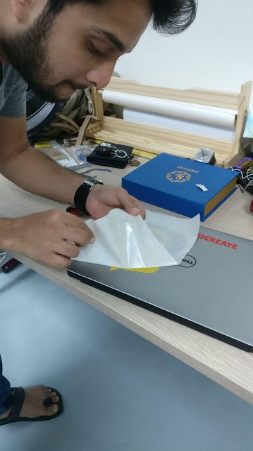
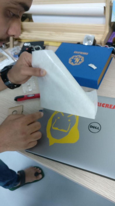
● Then again with good amount of concentration, I remove the masking material to obtain the sticker.
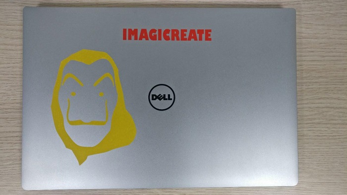
● And there it is, I have the Salvador Dali mask ready, It ain't a really complex design, bu for me to learn the entire process of converting the jpg to svg and using corel, machine setting and post process to achieve the final sticker. I am quite happy with the result. My reaction says all!!
my own 2d designed punisher sticker
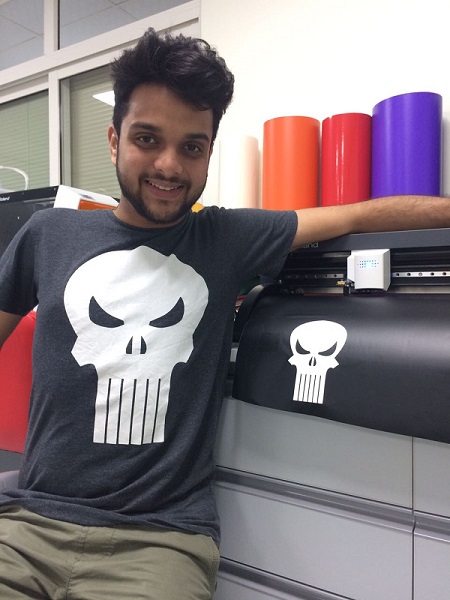
● I also designed the Punisher on Inkscape during the 2D Modeling Assignment in WEEK 02.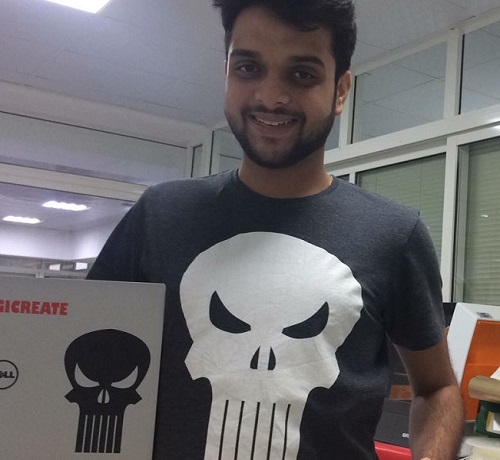
● I followed the same process on Corel Draw the Punisher file, I am glad I could actually design something so actual and similar to the the character on my T-Shirt.
i mean just look at that...
my personal progress
● Download the laser cut press-fit assignment files (.dxf)
HERE
● Download the laser cut parametric Fusion 360 file (.f3d) HERE
● Download the Inkscape designed Punisher sticker (.svg) HERE
●Download the vinyl cutting assignment files (.svg) & (.jpg)
HERE
● Well, after we start operating the laser cutting machine we moved to identify the “Kerf” of the cut and below is the table showing the details of the changes we made in order to make a perfectly fitting press-fit kit.
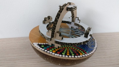
● Also worked on the steps provided to be followed on Fusion 360. Apart from that I created base structure for one the structure to assemble a press fit joint which will be updated in due time. it has been a busy week getting to know the Laser Cutter, the significance and application of the same.
● Using the skills that were obtained in this week will help work on the usage of vinyl cutter and laser cutter to be implemented on some parts of my final project. It's an awesome opportunity to get a hands on these machines and create something really productive, functional, valuable and creative at the same time.
● The experience on the vinyl cutter was very interesting as well, the editing done on Inkscape for the image to svg and then using corel to cut the sticker was valuable. The roland machine is also highly productive and accurate machine.
learning outcomes
● Learned to operate the very efficient universal system co2 laser cutter machine. Also comfortable with the machine software and Fusion 360 to make changes in the process parameters and material selection. An intense week in terms accepting the new stuff and absorbing all the work done.● Working on the roland ds-24 vinyl cutter machine has been less challenging now and an easy step by step process to follow. Working on corel draw has been a new interesting learning experience as well. Will be working on both the machines quite a lot throughout my time at the lab.
● i definitely learned lot of new topics in this week and now I feel much more confident in each aspect of this computer controlled cutting week.
● Experiencing with new materials for laser cutter such as cork board, acrylic and more materials in near future to create great press fit joints resulting in elevated structures.