getting started
● After a really informative lecture by Neil on computer controlled machining, on making something big, I was really curious to make something, but at the sometime I got a little confused on what to do and how to start about.● So I started to look for some inspiration for the same, and found some really cool ideas which caught my interest and were quite challenging to work on as well. So I found this website Free Patterns Area where they had all kinds of different and a range of projects.
● I found a lamp design and I immediately decided to do something similar, I am thankful for the website which allowed me to modify the design and I really appreciate that.
Testing the design on laser cut cardboard
● The lamp will look somewhat like this and the idea is to not make the design complex, but get the parameters right and learn how to operate the computer controlled machining technique by using the Shopbot.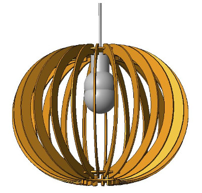

VISIT THE LINK
● The lamp was under the following license
Creative Commons License Official Page LINK
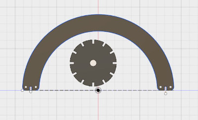
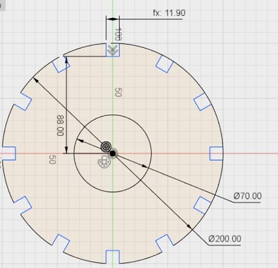
● I started designing the parametric drawing on Fusion 360 in two different sketches as an arm for the lamp with along with a top and bottom base to connect those arms in the form of the lamp.
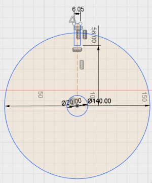
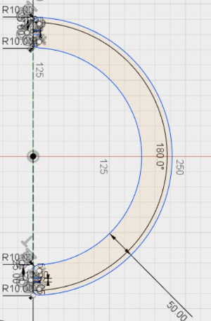
● I assigned dimension for the the components to test the the fit first on the laser cutter and then move on to the actual cutting process on the shopbot. I also assigned parameters for the same design so that I can modify the slots as per the material and design changes, the most important parameter was the slot of the arm and the base for a perfect fit into each other.
● This is the laser cut output of the same parametric lamp on 6mm cardboard. First couple of tests were not as perfectly fitting as I wanted them but Wendy helped me to modify the design on Fusion and try to add my own touch to it by changing the shape of the arm into rather attractive one and we also made some changes in the parametric slot dimensions to achieve the best fit possible.
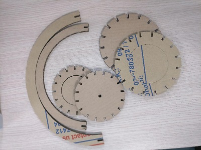
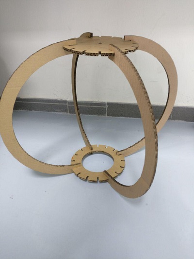
● After a couple of more test, below you'll find the prototype for the same as wee, which actually is a very good press-fit joint to be cut on the shopbot after some very minor alterations on the same.
The original design....
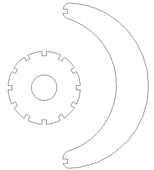
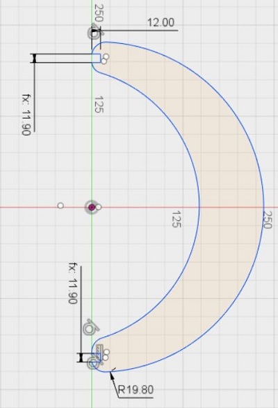
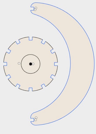
The modified design:
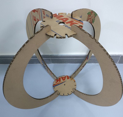
you can see how I have modified the design to make it different from the original one, to add little of my own designing taste and of course
the banana style lamp looks unique.
Vcarve process parameters
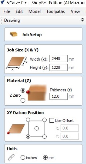
● We started to work on the software to learn it and try how the tools are used. This is how the home page looks like for VCARVE software used for Shopbot. We edit the job size as
● W= 2440 H= 1220, the material thickness as 12 mm. Also the untick the checkbox for the use offset setting and changed the units to mm.
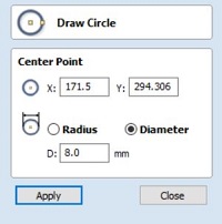
● Once we are done placing the components and adjusting the job set up as specified above the next step is to assign the screw drill holes on the vcarve software by adding some circle with the 8mm dia near the parts to make sure the layer of the wood we'll be using is tightly joined with the layer below it.
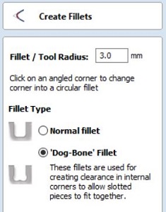
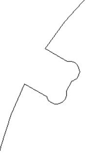
● This is the most interesting part I felt in the Vcarve software, also the most essential to achieve a really tight fitting part. The idea was to create a fillet in the slots that were designed in the parametric model, as you can see in the image below the Dog Bone fillet was used with 3mm Radius size. The same was applied to all the slots including the base and the arms as well.
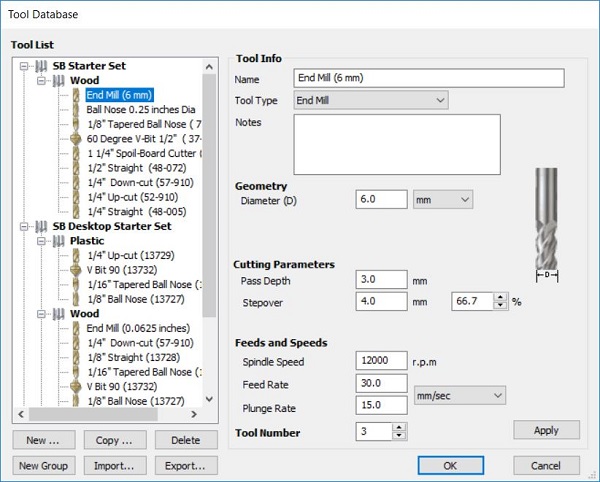
● For testing the file, my first cutting operation, the 6mm End Mill is what we wanted, with 6mm Dia, Passdepth, Stepover as 4mm, Spindle speed as 12ooo r.p.m, Feed Rate 60 and Plunge Rate is 30. These process parameters were quite harsh and Wendy explained us to keep all other settings the same and to change the Feed rate at 30 and the Plunge rate 15.
● So.. for the final test we select 6mm End Mill, with 6mm Dia, Pass Depth is 3mm, Stepover is 4mm, Spindle speed at 12ooo r.p.m, Feed Rate 30 and Plunge Rate is 15... as shown in the image below. We select the similar database for toolpath for each of the toolpaths to be calculate as we will be using the same tool to cut on the Shopbot.
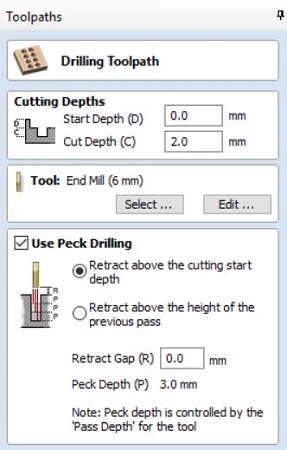
● Then moving on to the selection of the end mill tool for just marking the points where the screws will be placed, so we select the Cut Depth: 2mm to make sure the marks are actually visible on the layer. Also in the software, we make sure that all the screw are on the seperate layers as compared to the main cutting part, then we select the following parameters and calculate the cut toolpath for the same.
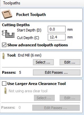
● Next step is to move on calculate toolpath for the base and the arm of the lamp by selecting the pocket toolpath for the inner circle of the base as we want the circle hollow from the centre as specified in the design on fusion.
● And then we select the profile toolpath for the outer circle of the base and the arm design. Also to ensure that we are following the similar and correct process parameters or settings for the profile toolpath.
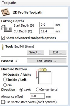
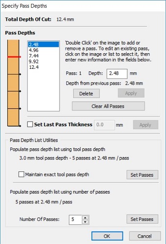
● The pass depth is one of the important tools to set a certain no. of paths and specify the machine to follow the same path as mentioned. Also we can adjust the depth of the pass as well. We kept 5 passes for the profile toolpath.
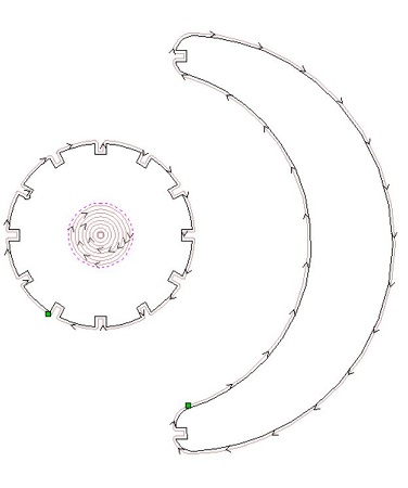
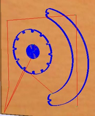
● This how the toolpath represents itself on the software expressing the direction of the paths, cut and the layers as well, according to the process parameters. Also the tabs and the drill paths for the screws.
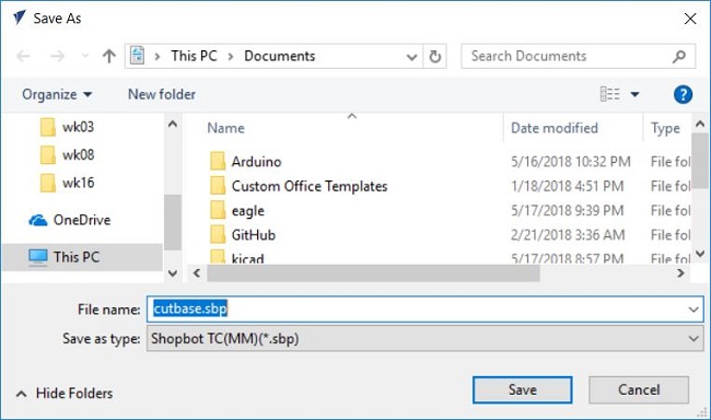
● The we first the save the vcarve file from and move on to save the respective toolpaths separately in the form of (.sbp) for shopbot cutting software to recognize the same. Naming convention for these files were based on the parts of my lamp, such as, base and arm. Below is an example of saving -cutbase file in (.sbp)
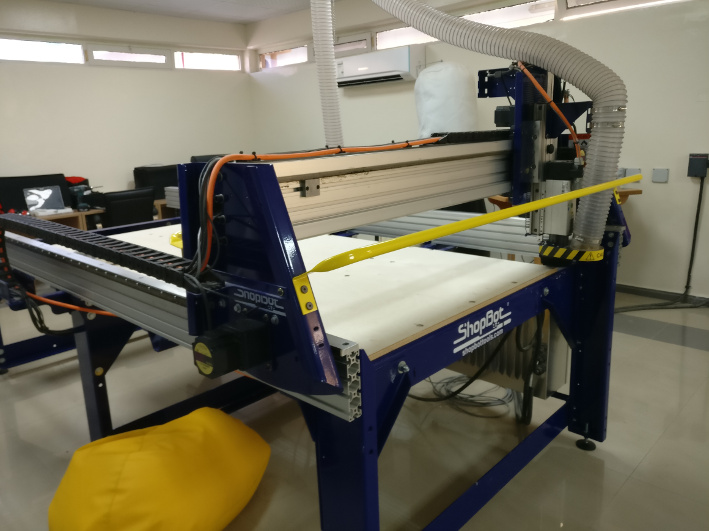
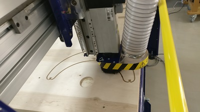
it's shopbot time
BUT
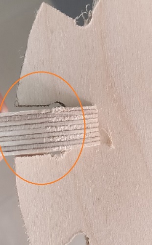
● Once the cutting operation was completes I faced a new CHALLENGE !!!!
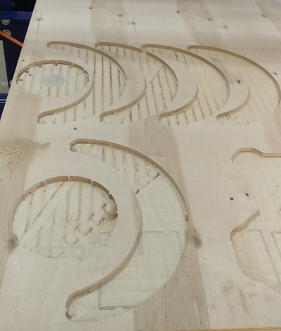
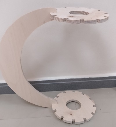
● I did not realize, due to my mistake I scaled up the base design by a little margin on the vcarve software because of which I achieved the following output. Also the fit was a little bit loose. ● I learned from the mistake that I should have focused more while working on Vcarve and also double check the same before I proceed to cut the same on the machine.
● As you can notice in the images shown that the base was quite bigger in its horizontal dimension compared to what dimension I specified on Fusion 360 software while designing the same.
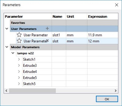
● The following image shows the modification done by me after the failed test, I made sure that the dimension of the base was the actual size size to be cut out and also modified the user parameters for my slots on the base and the arm, as specified in the below image.
● the slot of the arm is at 12.00 mm and the slot for the base is at 11.90 mm
● The following is the parameters I saved and proceeded to follow the above process on the Vcarve software.
Back to the BOT....
● The best part about committing such a mistake was that I got a chance to learn from it, also I cherished the opportunity to work on the software, vcarve process and the machining part.
● Also spend more time with the expert Prof. Wendy herself and as she rightly mentioned I honestly feel much much more CONFIDENT about the Shopbot now !!!
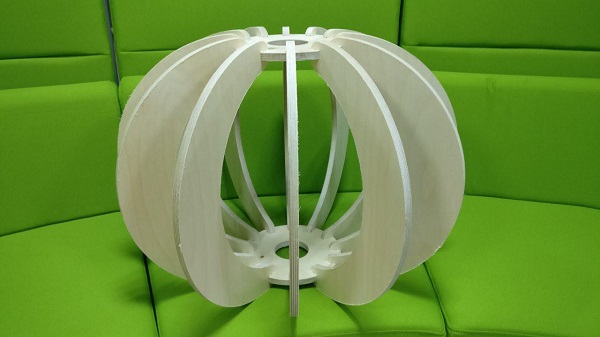
looks neat and ...
Something big !!!
That smile as well :)
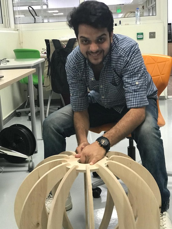
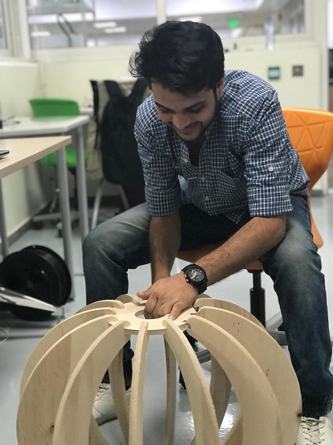
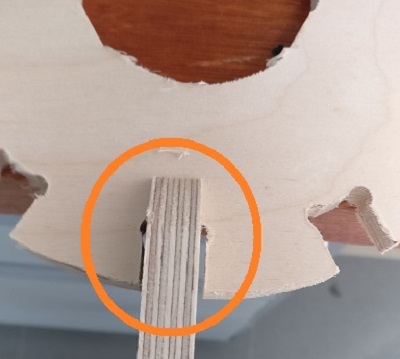
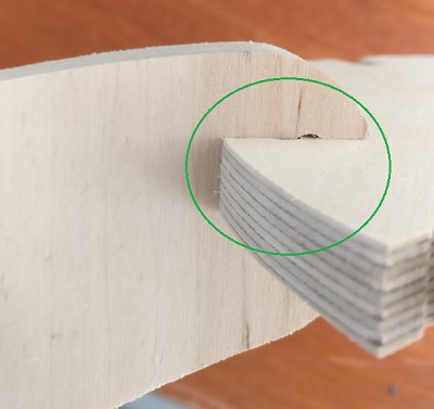
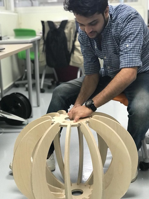
● The slots were fitting really well with each other and I can feel that they are quite strong and tight once joined together. Obviously needs some sanding to be done and it's good to go.
A big hug to myself..
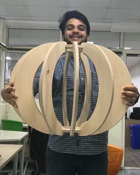
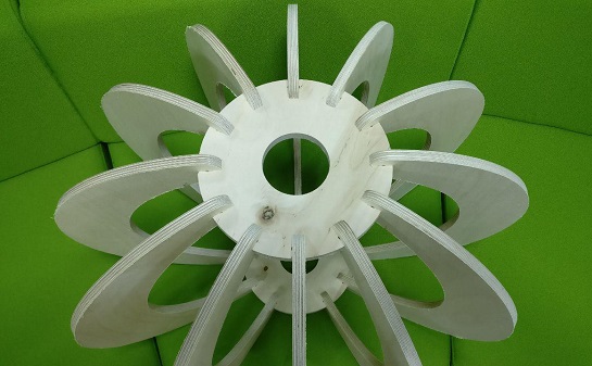
lamp is ready
Learning outcomes
● Download the files for my Lamp assignment (.dxf)
HERE
● Download the Parametric file for Fusion 360 (.f3d) HERE
● I learned a lot more about the parametric designing on fusion 360 and getting better at it daily as much as I practice and keep on applying the same on my assignments. It is super interesting to work on Fusion with students around me who also were new to the same and that's how you actually learn more from others.
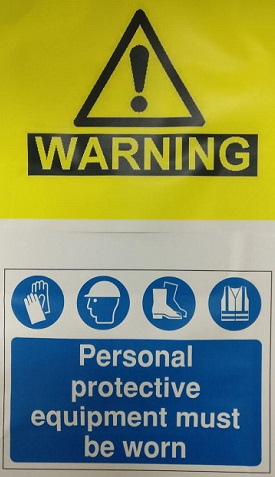
● Also learned a lot of essential stuff on vcarve software to help me set up the parameters for my cut on shopbot, edit tabs, pass depth, how to save the files, work on the machine, always keeping in mind the safety aspects and to ensure the cutting is done smoothly.
● Also learned a thing or two about fixing of the shopbot in terms of the bed, axis and other essentials before cutting out a job on the same.