getting started
● Again a very interesting topic this week and Neil gave us a rather understanding about embedded programming, I did not connect to everything he said, but tried to catch the basic stuff at least. It is indeed a whole new world for me and it's quite intriguing to know more about the same.● I am looking forward to this week, starting with going through the datasheet for the Attiny 44, which looked seriously boring with 250 odd pages of pure text, more like alien talking to me. Nevertheless, the idea was to search for the points which could help me understand more about a particular component, its implication and application as well.
● Hashem gave us a good session on Arduino and how to connect everything, edit the code in terms of the pins connected also, step by step process to do the entire programming. He gave us useful tips and links for a much better idea of what we are doing and why.
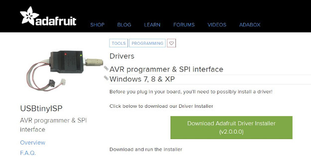
● It was essential to download the following driver for the machine to recognize the USBtinyISP and then moving on to program the board using fabISP I made in Electronics Production week.
Here is the Link to download the Driver from adafruit website.
attiny 44 datasheet
● Most of the content below is taken from the datasheet and I have made an effort to try to explain in my way as much as I could, so do visit the link of ATTINY 44 datasheet to have a look at the same.
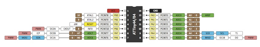
● The below image shows the very important pinout for the Attiny 44, in order to make sure of the connections and also the placement of the component. Also shows the analog and digital pins with specific functions, roles etc. At the top we can see the VCC and the Ground as well.
Pin Descriptions
VCC● Supply voltage.
GND
● Ground.
Port B (PB3...PB0)
● Port B is a 4-bit bidirectional I/O port with internal pull-up resistors (selected for each bit). With a pull-up resistor, the input pin will read a high state when the button is not pressed. In other words, a small amount of current is flowing between VCC and the input pin (not to ground), thus the input pin reads close to VCC. When the button is pressed, it connects the input pin directly to ground. The current flows through the resistor to ground, thus the input pin reads a low state. Keep in mind, if the resistor wasn’t there, your button would connect VCC to ground, which is very bad and is also known as a short. I'm trying to catch up with a whole new world of electronics learn this stuff which is quite new, challenging and also interesting from various websites and tutorial, so this Sparkfun page to know more about pull-up resistors.
RESET
● Reset input. A low level on this pin for longer than the minimum pulse length will generate a reset, even if the clock is not running and provided the reset pin has not been disabled. Shorter pulses are not guaranteed to generate a reset.
Port A (PA7...PA0)
● Port A is a 8-bit bidirectional I/O port with internal pull-up resistors (selected for each bit) as well as compared to the 4-bit Port B.
FEATURES
● The ATtiny24A/44A provides the following features:● 2K/4K byte of In-System Programmable Flash,
I have an idea about only this particular feature of the byte space available on board because, my classmate Zubair faced this issue where the program he added from Arduino required more space than available on the microcontroller and he realized the significance of the same.
Rest all the features below of the microcontroller are really new for me but I wish to learn more about it as I move forward.
● 128/256 bytes EEPROM,
● 128/256 bytes SRAM,
● 12 general purpose I/O lines,
● 32 general
purpose working registers,
● an 8-bit Timer/Counter with two PWM channels,
● a 16-bit timer/counter with two PWM channels,
● Internal and External Interrupts, a 8-channel 10-bit ADC,
● programmable gain stage (1x, 20x) for 12 differential ADC channel pairs,
● a programmable Watchdog Timer with internal oscillator,
● internal calibrated oscillator,
● and four software selectable power saving modes.
this series of tutorial by jeremy blum helped a lot in understanding Arduino.
● Pulse-width modulation (PWM) is a modulation process or technique used in most communication systems for encoding the amplitude of a signal right into a pulse width or duration of another signal, usually a carrier signal, for transmission.
● Pulse Width Modulation, or PWM, is a technique for getting analog results with digital means. Digital control is used to create a square wave, a signal switched between on and off. This on-off pattern can simulate voltages in between full on (5 Volts) and off (0 Volts) by changing the portion of the time the signal spends on versus the time that the signal spends off. The duration of "on time" is called the pulse width. To get varying analog values, you change, or modulate, that pulse width. If you repeat this on-off pattern fast enough with an LED for example, the result is as if the signal is a steady voltage between 0 and 5v controlling the brightness of the LED.
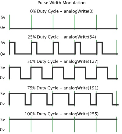
● In the graphic above, the green lines represent a regular time period. This duration or period is the inverse of the PWM frequency. In other words, with Arduino's PWM frequency at about 500 Hz, the green lines would measure 2 milliseconds each. A call to analogWrite() is on a scale of 0 - 255, such that analogWrite(255) requests a 100% duty cycle (always on), and analogWrite(127) is a 50% duty cycle (on half the time) for example.
Different PWM Operational Modes
● Below is some content again which I don't really understand much, but wish to know the application of the following modes. But indeed it's interesting to read about PWM from the datasheet.Normal Mode
● The simplest mode of operation is the Normal mode . In this mode the counting direction is always up (incrementing), and no counter clear is performed.
Fast Mode
● The fast Pulse Width Modulation or fast PWM mode provides a high frequency PWM waveform generation option. The fast PWM differs from the other PWM option by its single-slope operation.
Phase Control Mode
● The phase correct PWM mode provides a high resolution phase correct PWM waveform generation option. The phase correct PWM mode is based on a dual-slope operation.
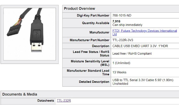
ftdi
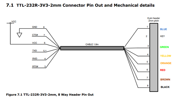
● Another important data sheet I went through was the FTDI cable datasheet. It was just a couple of pages and really easy to understand what it stated. The connector pin out is shown in the image below and I used this extensively to make sure of the correct connections while using the FTDI cable.● Check out the datasheet for FTDI

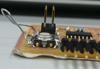
● The ONLY challenge I faced this week was that I printed the wrongly designed (out of the 2 boards I designed in electronics design week) circuit board in order to programme this week and I realized that this was the issue, but instead of printing a new circuit board I decided to hack the wrong design and make it work.
● Wendy and Salama helped a great deal in terms of understanding what traces needs to be removed and what needs to be connected in order to make this board work. It was not a major hurdle but it was quite an intense one of it's kind experience for me to hack the board. I'm glad I learned a valuable lesson.
● As shown in the image below I used a soldering wire to connect the ground to ground on the button, before which I cut an extra trace which was not needed.
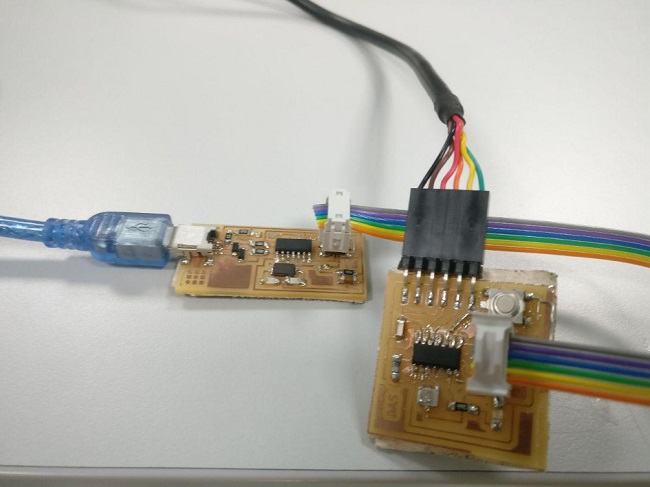
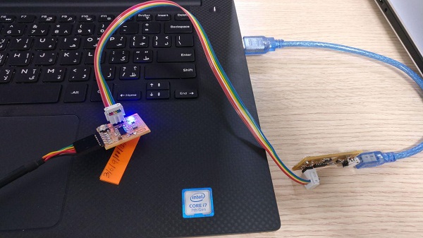
● Once both the boards connected properly using the daizy cable connecting the AVRisp to the FABISP, also the FTDI cable to connect to the laptop as shown in the below image, we start using the Arduino software in order to modify the process parameters for programming and uploading the code.
● The connection was done in the following manner for the required programming output.
● Used the FabISP for programming that I made in Week 04 to program this Board.
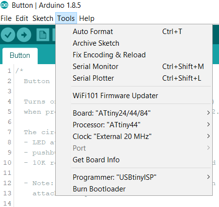
● As you see, we select the ATtiny 44 Board, ATtiny 44 processor, clock at 20 MHz and the programmer as USBtinyISP.
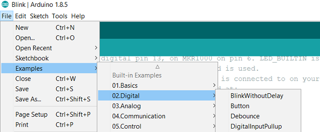
● Moving on to File/ Examples/ Digital option and choose blink and button for uploading the sketch code and proceed with the programming.
● Below you can see the example Blink code, the code starts with the void setup command which means to start the setup routine followed by an pinMode command which configures the specified pin to behave either as an input or an output, in my case, the LED pin is connected to Analog output pin 7 on the ATTINY 44.
● Then I proceed to the Loop function, which runs over and over again. Inside the Loop we have digitalWrite function, which writes a HIGH or a LOW value to a digital pin. In which High means the LED shall be turned on and then we add a delay of 1000 milliseconds and then LOW to torun of the LED. So, therefore with the above loop code, the LED starts blinking with a delay of 1 second between turning off and on. I can change the delay function as per requirement, but this is the overall understanding of the below mentioned code.
blink code (modified)
●Download the modified Arduino blink code HERE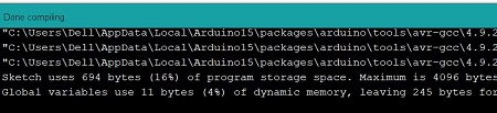
Once Verified and Done Uploaded we can see the board has been Programmed
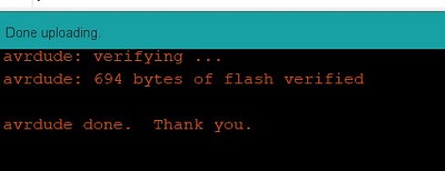
● So finally I successfully programmed the PCB I made, using the FabISP also made by me. After all the hassle of datasheet and making sure of the correct connections, this week bought a very valuable learning experience for a newbie like me.
● Below is the video to show the
led blink test
testing a button code
● It's indeed a fairly simple code and rather interesting for me to understand the arduino and its functions. The pushbutton is a component that connects two points in a circuit when you press it. The example turns on an LED when you press the button.● I modified the code in terms of changing the pins connected to the LED(pin 7) and Button(pin 3) on the ATtiny44 microcontroller. Also by using the INPUT_PULLUP function in void setup command to activate the internal resistor present on the microcontroller.
● When the pushbutton is open (unpressed) there is no connection between the two legs of the pushbutton, so the pin is connected to 5 volts, and we read a HIGH. When the button is closed (pressed), it makes a connection between its two legs, connecting the pin to ground, so that we read a LOW.
● Keep in mind that setup( ) routine runs only once after power on / re-program or press the reset button. In the program below, the first thing you do is to initialize the button pin as input_pullup and the LED pin as an output pin with pinMode( ) function in setup( ) routine.
● The loop( ) routine runs over and over again, forever. In the main loop, you read the state of button and you store it in buttonState variable. When button pressed once, the led turns on, and when pressed again, the led turns off.
button code (modified)
● Download the modified Arduino button code HEREled button test
also tried
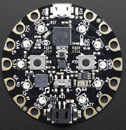
adafruit circuit playground
● This is an all in one board that has sensors and LEds built in. A very good way to practice programming on real hardware with no soldering or sewing required. This one is the classic version which comes with ATmega32u4 and it's designed to be used with Arduino IDE or code.org.
● ATmega32u4 Processor, running at 3.3V and 8MHz
● Micro USB port for programming and debugging with Arduino IDE
● USB port can act like serial port, keyboard, mouse, joystick or MIDI
● This product is available on the Adafruit Website
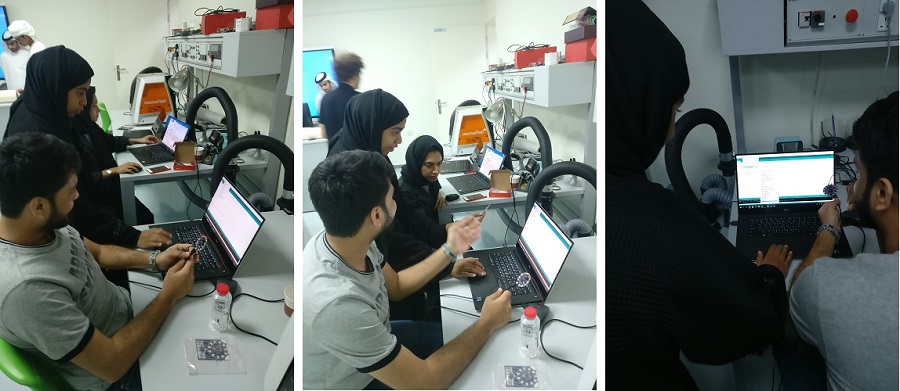
● Me, Salama and Zahra started to play around with it, by connecting it to the Arduino IDE. As Salama had a pretty good background knowledge about it, so it was really nice to learn from her about the connections, codes and to know more about this particular product.
● So, we decided to use a bread board and test a blink code, in this process we connected the ground and vcc from the Circuit Playground to the breadboard and also added a resistor to test the normal LED. The idea was to program the LED on the breadboard using the Circuit Playground via Arduino IDE.
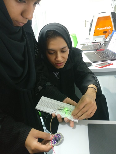
● And, we were able to program the LED through the Circuit Playground. Below is a video showing the working of the same.
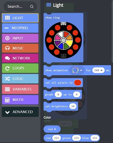
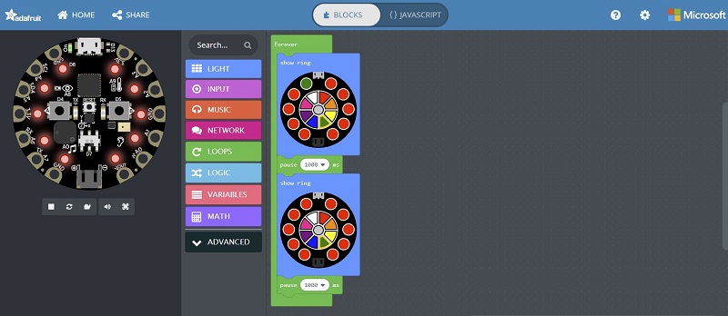
● Next step was to test and play around with the neopixel programmable LEDs on the circuit playground itself. To do the same, I visited the makecode.adafruit Website. It was a super fun experience for me to experience programming is sucha different and colorful environment like never before. The website let me drag and drop stuff to create a program using blocks as shown in the image below. So I picked up the LED ring from the light option where I could modify the parameter for animation of lights in milliseconds.
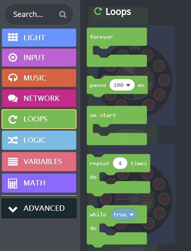
● Next step was to add blocks from the loops option, where I could choose stuff pause,delay, repeat and forever as shown below.
● So this is the final creation for the program in blocks along with the use of forever and pause tools as well. As we can see the product on the right side of the website, which is a simulator for the code as well, where I could run the code and see the LEDs blinking in the same pattern, along with play a sound from the speaker available on the circuit playground itself. Also an option to run the simulator in slow motion and in full screen. I was already in love with this, hahahaha.
● The website also had a provision where I could turn the blocks into a javascript just by a click of a mouse. The javascript explains the entire creation which was made by blocks into a script. So I uploaded the code on the and I could see the LEDs working in the same way.
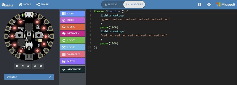
● And yes, they had to work, because it was all so superbly put up on the website that there is very little scope for any error. Really interesting product and very enjoyable way to get introduced to programming using the make code website.
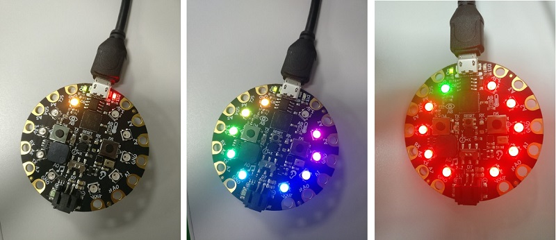
● Below is a small video showcasing the working of the same code on the Circuit Playground. Special thanks to Salama for making me introduce to this intelligent,lovely and powerful little piece of hardware.
learning outcomes
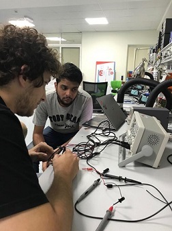
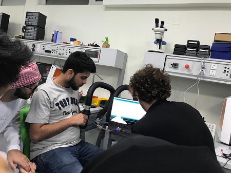
Session on oscilloscope
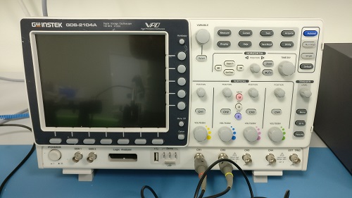
● We, the students, were glad to get the opportunity to know some essentials of the oscilloscope in the session conducted by Gabriel, who is the winner of World Skill in the electronics segment. I had to catch my flight for Mumbai as we were nearing the break so unfortunately I could not attend the entire session but nevertheless, I learned a thing or two about the functions and how to use the same.
● It's used to observe the change of an electrical signal over time, such that voltage and time describe a shape which is continuously graphed against a calibrated scale. The observed waveform can be analyzed for such properties as amplitude, frequency, rise time, time interval, distortion and others. It had all the fancy knobs, which are used to change the range of signal (Volts/div) or time and sometime to perform measurements.
also
● Datasheet of the LED was quite helpful.● Check out the datasheet for the switch Button
● The datasheet for Analog Mic and RGB LED guided me for the assignments (Input & Output) of Week 11 and Week 12 as well.
● Learned a great lesson of hacking a PCB and making it work, it has been a super week and the learning atmosphere is growing.
● Learned how to read a datasheet to help myself with a much better understanding of the components about their applications and connection.
● Learned how to connect the board designed by me and the fabisp inorder to program the former with the help of the fabisp.
● Learned how to use arduino to program a board with the button for the led to lit up using example codes provided by Arduino IDE.