
Lingyu Yue @ FAB LAB Szoil · 2018
© 2018 Lingyu Yue · Template by Bootstrapious

This work is licensed under a Creative Commons Attribution-NonCommercial-ShareAlike 4.0 International License.
Electronics Production
Assignments
Characterize the specifications of your PCB production process
Make an in-circuit programmer by milling the PCB (program it, so that you can use it to program your board in Electronics Design week, and in other weeks)
Optionally, trying other processes.
For electronic production, I only had done one plug-in PCB(printed circuit board) which called drawdio (inspired from Jay Silver). And a maker named Luke taught me the basic about Fritzing App.So this page describes my learning process to mill and to solder SMD.
I really struggled a lot about the milling and soldering, and I wasted a lot of time at finding the components. What I learnt most was I had to follow the instruction and figure out the exact process about making instead of rushing to make. Anyway, I still had a lot of fun during this assignment.
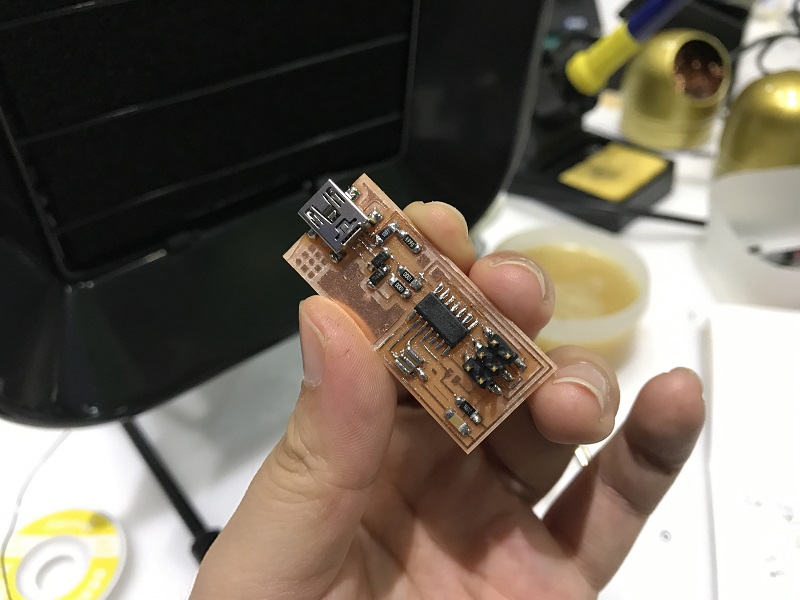
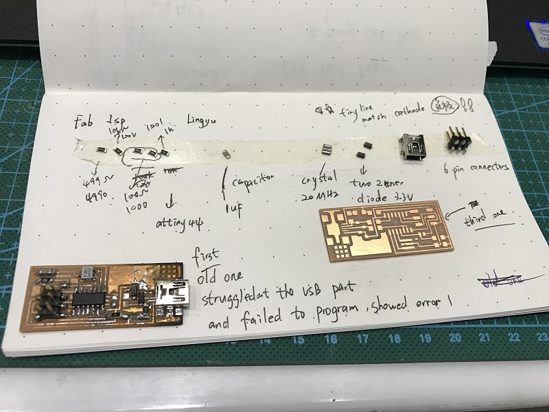
Making an in-circuit programmer 'FabTinyISP'
I chose to make an Attiny44 FabTinyISP, I searched the detail on Ali's page
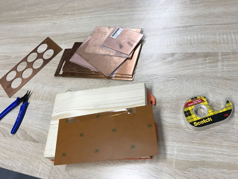
Preparing the milling machine Roland SRM-20
For milling I used Roland SRM-20 Desktop Milling Machine.
First of all,I loose the screws and remove the wooden plate. Then I use 3M sticker to glue the Copper Board on the wooden plate to prevent it from moving aside.
Open the program ‘VPanel for SRM-20' and set the origin of Z-, X- and Y-axes:
- Move the head to the View position so that it moves to the center and it is easier to install a milling bit.
- X- axis moves the table, and and Y- and Z-axes move the head.
- Move the axes manually by the VPanel arrows with appropriate Cursor Step.
- Continue moves as long as you push it, by which you will move near to the aimed origin.
- x100 does smaller steps to get closer and
- x10 0,1 mm steps to get nearby the surface.

After setting the position of X- and Y-axis,I need to move the Z-head careflly to the surface and loose the small screw to make it stay on the surface manually. And then reset the z-axis It's easy to break the bit if you adjust it with the programm.
I downloaded the .png -files Traces and Outline Cutout below,
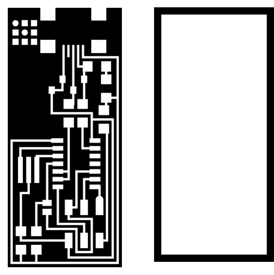
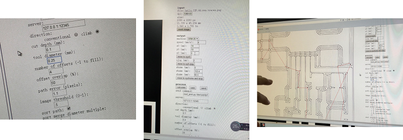
and used fabmodules.org to make the .rml -files for Roland SRM-20 milling machine .
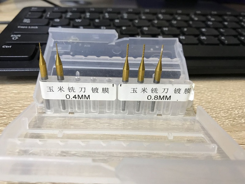
I use 0.4mm milling head to cut the traces and use 0.8mm milling head to cut the interior.

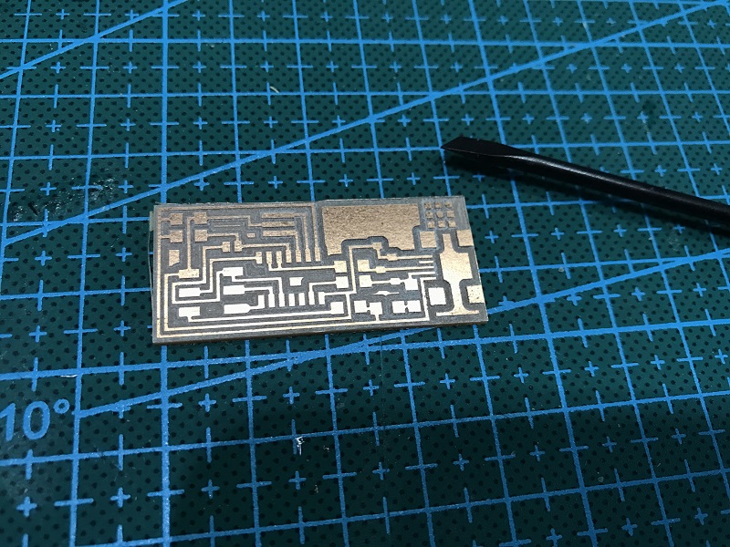
With different setting option,I have two boards.I chose the second one.
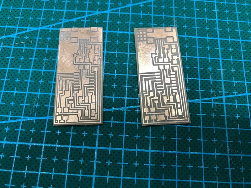
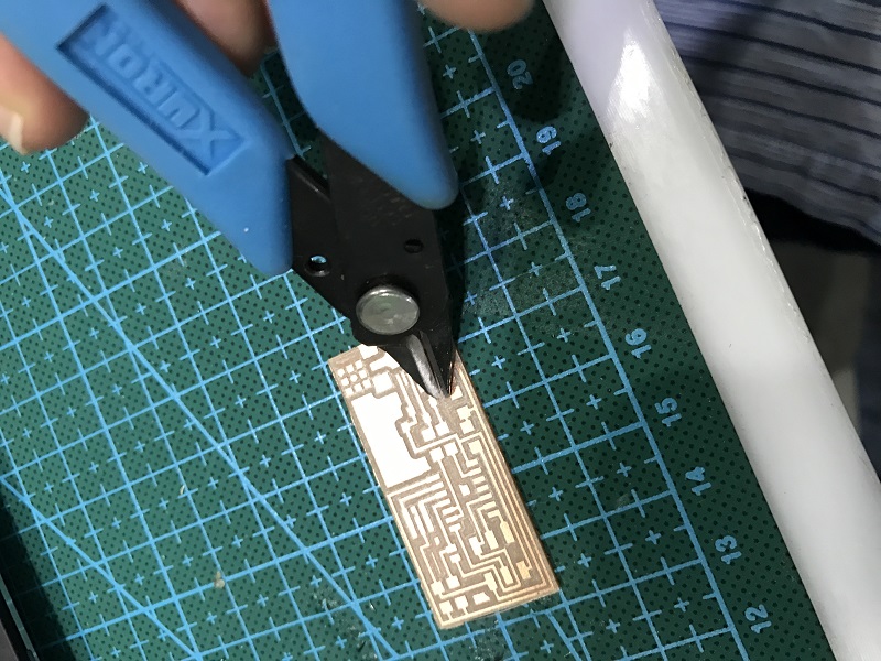
After milling, I removed the extra part of the board ,wash it and then polish it a little.
Assembling the PCB
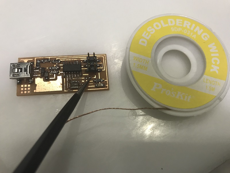
First of all, I collected the tools needed: soldering iron, soldering tin, desolder braid, tweezers.Remember to wet the sponge of soldering iron for cleaning the tip of the iron.
Start soldering.
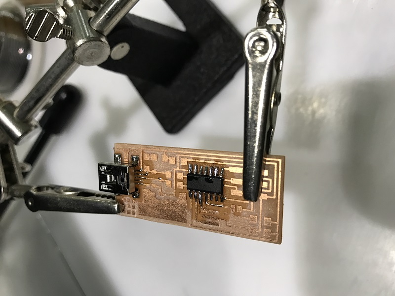
Check if the chip is solderd properly.
I failed for the first and second board, after soldering and adjusting several times. I destryed the surface and some components. So I prepare all the things again and start form the very beginning.
The hardest part for me is soldering the USB,I kept shaking my hand.
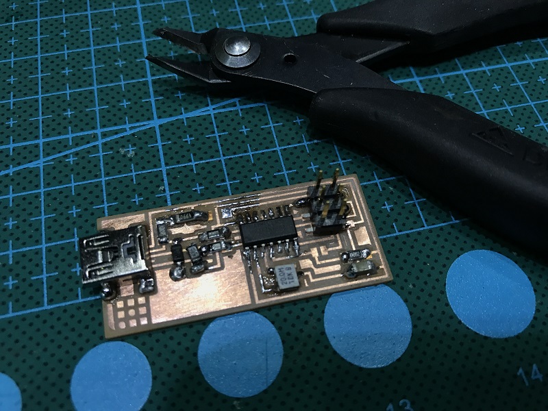
After soldering several times,I can solder better.

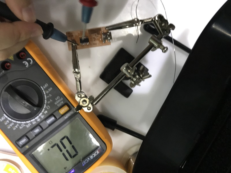
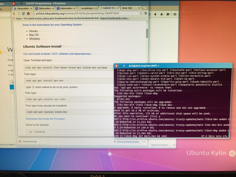
Programming the PCB by FabISP programmer
I followed the Programming Instruction step by step, used the computer with Ubuntu system in Szoil.
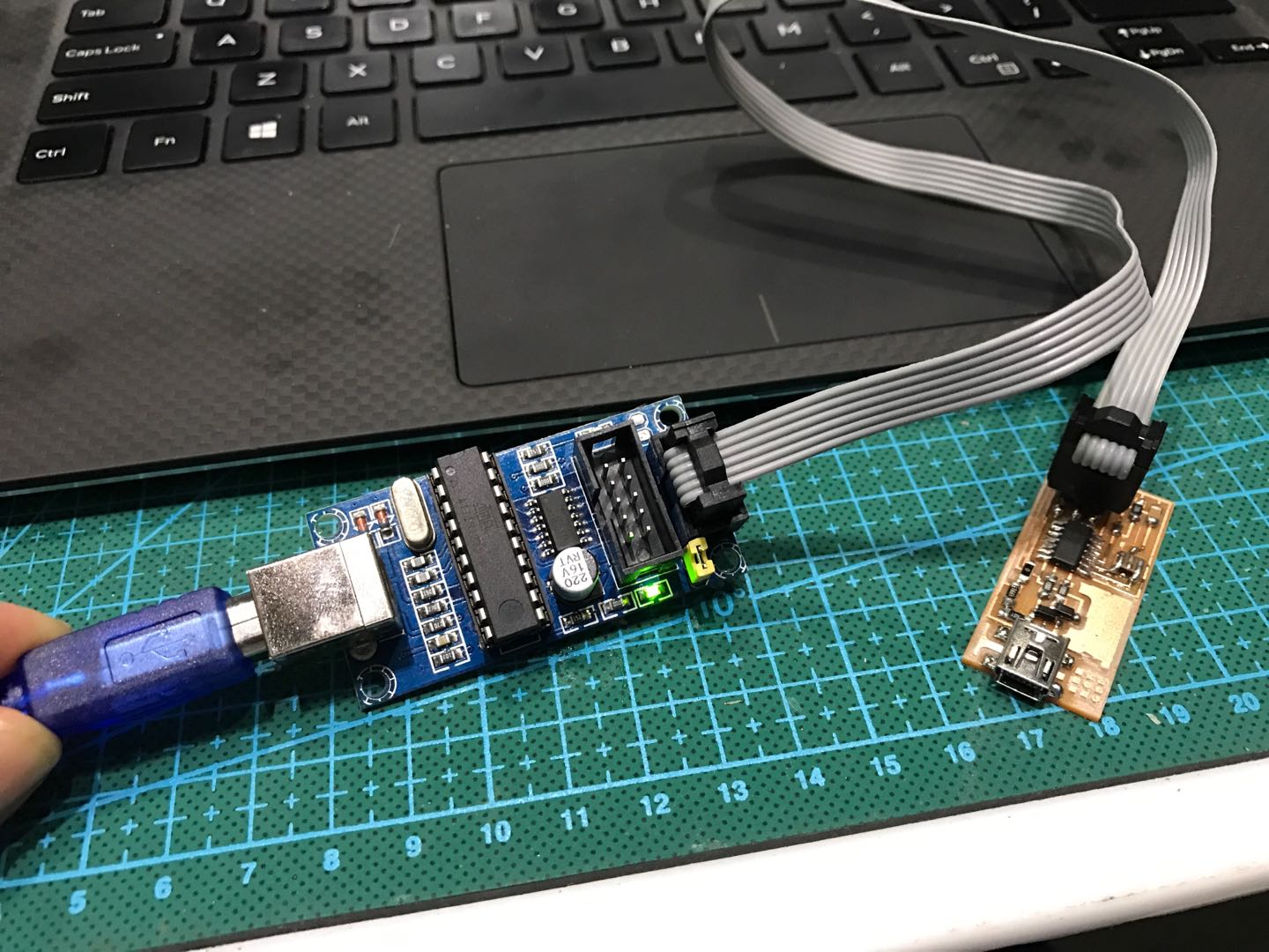
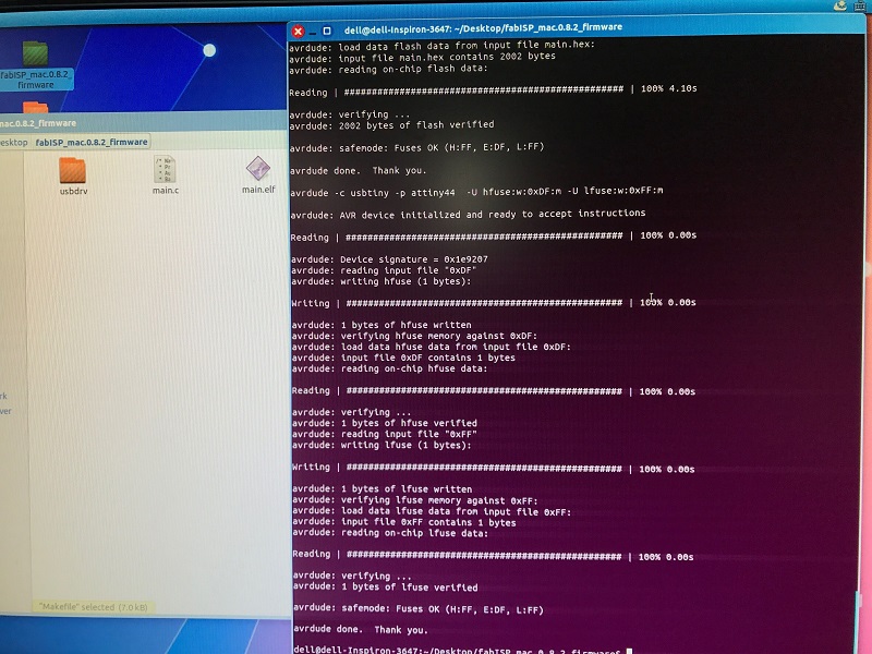
After progamming, I removed the temporary connection for supplying voltage.
Here are the .rml files of The FabTinyISP rml file.