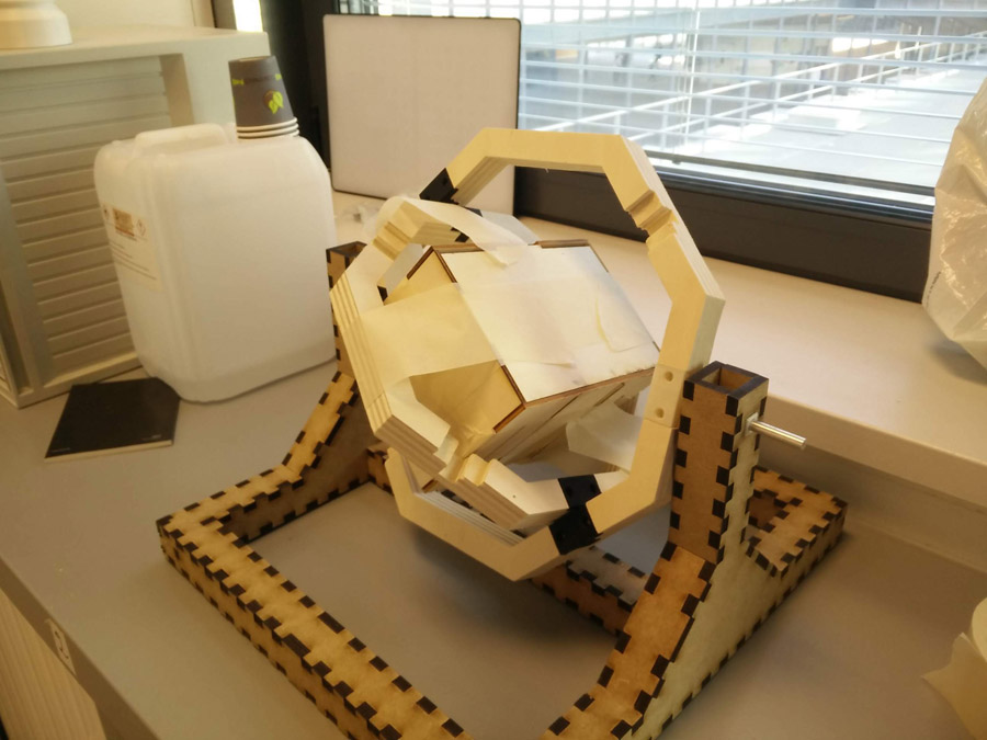
15. Mechanical Design
As a group, we built a rotational casting machine. This week, I worked on the central chamber to hold the mold in place. I also reviewed alternatives to 3D printing my final project - creating a silicone mold for the cone top that could wrapped under the base.
Final Project Work
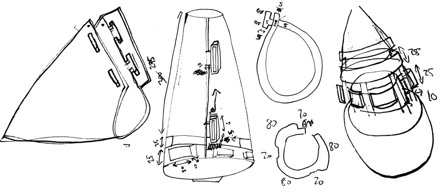
The mold would be made of a 5mm thick piece of silicon layed flat. I would most likely use the silicone as in the molding and casting week. I considered assembly of a cone looking at a video by Alexander Dyer, which led me to a cone calculator page.
The sides of the flattened cone could have a sort of flat button system, allowing the material to wrap into shape. The lower section of the top would have a series of bumps that protrude outward. I could push these bumps through gaps in the upper part of the base.
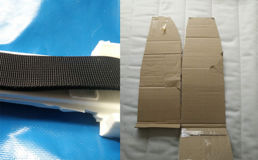
I had used the silicone mold on another pannier – It feel and thickness gave me an idea for the strength of 5mm thick cone top. The material would need to support impact from a football - compared to PLA/ABS it would not (fully) hold its shape but this is a minor issue. It is also heavier and more expensive to use - 1kg currently costs €61.90. It will take a bit of experimenting to get the weight of the base (with sand) right: A balance between it holding itself upright on impact and moving freely. If the top is too heavy, the buoy could be very sturdy and difficult to move – I would like some movement for the players to visualise. It was also useful to consider an earlier prototype done in cardboard.
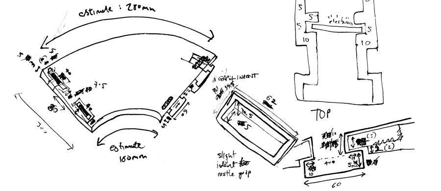
I estimated the dimensions for each part, including the interior support for a disc housing the electronics. When using the flat buttons, a dip on the opposing size would allow the material to remain flat.
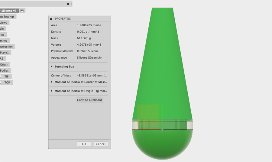
In Fusion 360, I did a straight comparison between ABS and silicone by adjusting the material on the cone top. I returned to my file in progress, removing the grip gap which probably would not work with a flattened piece. Without creating the additional bumps in the lower section, the cone top was already 613grams.
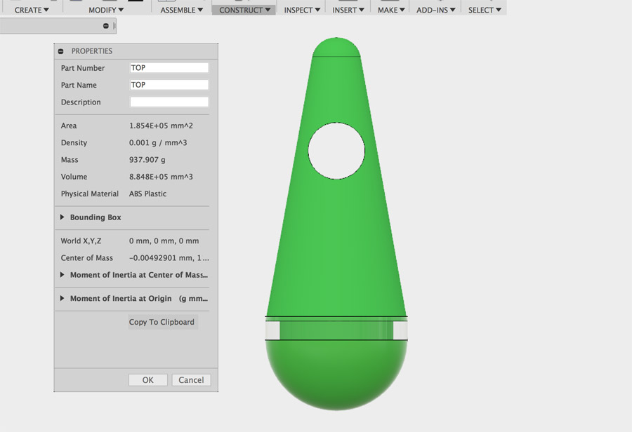
Based on weight and recommendations from Adel, I decided to proceed with a 3D printed piece and find ways to print my design on the Ultimaker 3. The leads appropriately to week 18 where we had to workout material cost.
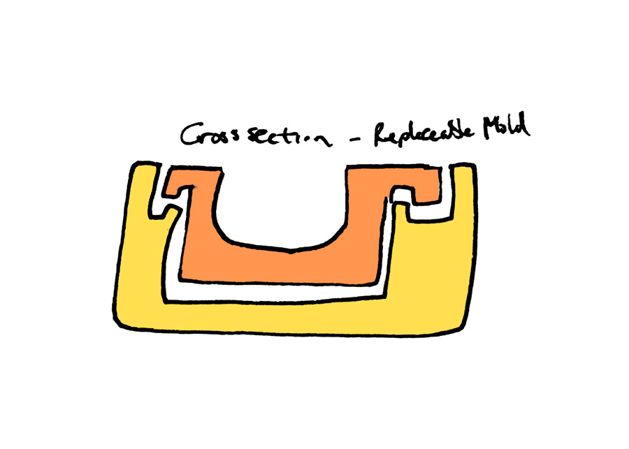
Roto-Casting - Cylindrical Chamber
My initial idea was to 3D print a cylindrical shaped cast, similar to one I'd seen at a rotational molding factory. The idea was to create a clip using a living hinge to hold the two sides in place and close it around two bars running on either side.
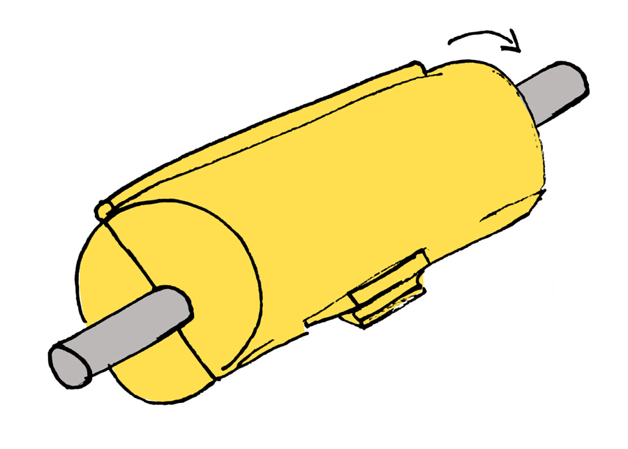
The cross-section shows how a tray within the cast could be placed to reuse the different casts.
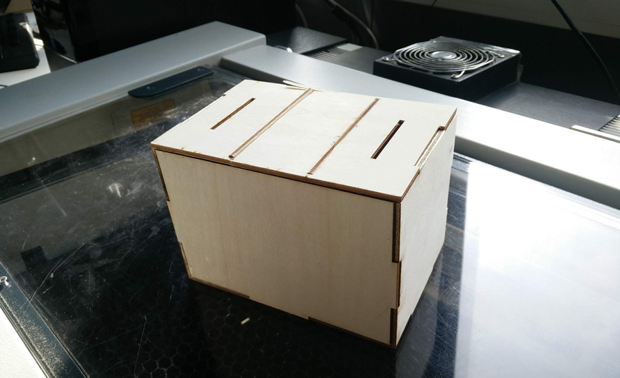
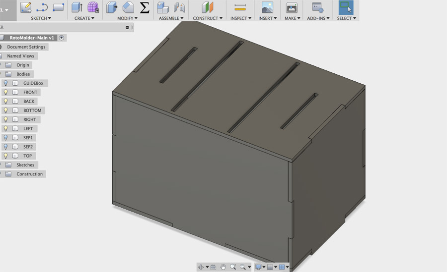
Roto-Casting - Box Chamber
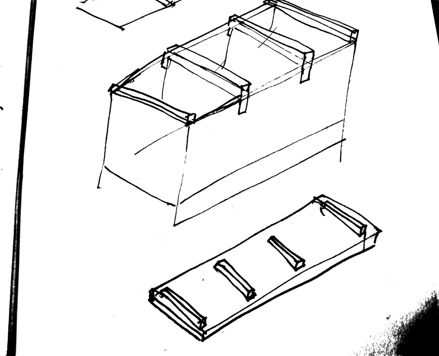
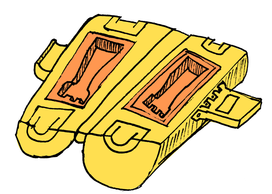
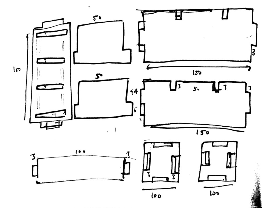
Based on the time constraints, it was decided that the early concept would take too long to print. An alternative was to create a press-fit box that could function in a similar manner. I set about sketching a chamber with two dividers, similar to a filing cabinet layed flat. To this, I added a top layer which could be placed over the dividers to seal the chamber. On paper, I worked out the dimensions to be used parametrically.
Fusion
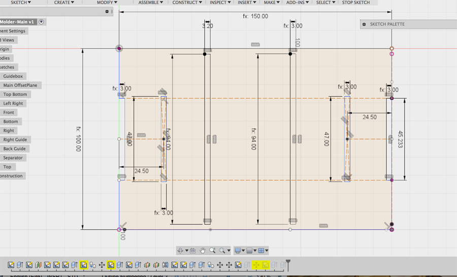
I started working parametrically, entering the amounts in the 'Change Parameters' menu. Despite working out the dimensions, I found it challenging to match up the sides of the press-fit construction and make sure they fit appropriately. I extruded each sketch as a body to check that pieces fit together.
I created a significant amount of construction lines which I needed to remove on transfer to Inkscape. To do this I created a copy of the file in a separate folder named 'production'. Here, I removed all bodies and lines that were not required – Make sure you have the correct copy open before deleting anything!
When the sketches for each side were cleaned up, I right-clicked on each and selected 'Save As DXF'.
Inkscape
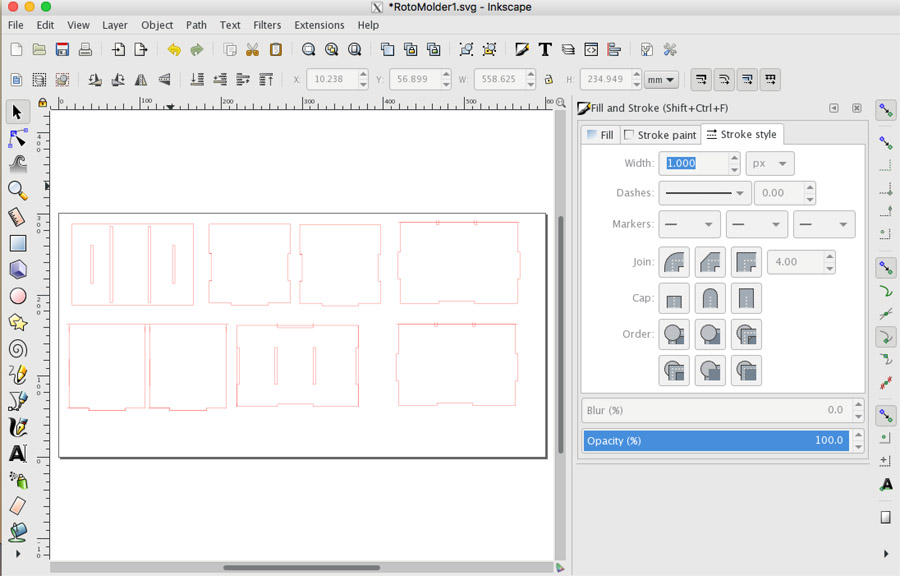
In Inkscape, I transferred all DXF to one file with dimensions of 600x300 and saved it as an SVG. I converted all lines/stroke to RGB 255 with a thickness of 1.00px.
Assembly
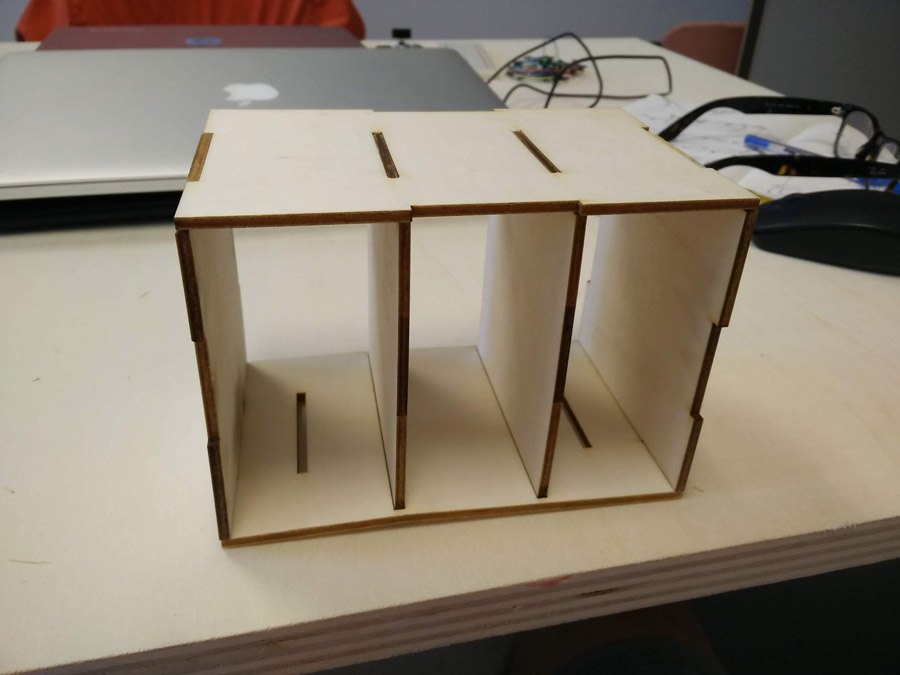
Assembly proved challenging because the parts were wafer thin (well, 3mm). The plywood was used for this test and final prototype. I used scotch tape to help me assemble the parts initially, later I used glue. We wanted to ensure that the chamber stayed together on rotation. We also needed to connect it to the axis in some way.
I had to return to Fusion on a couple of occasions to redraw and export sides of the chamber. With so many construction lines, I had confused the height of certain heights and parts did not fit. I also had to adjust the top and bottom layers to include a space for attaching the grips we had in mind. The other issue in Fusion was that I had created a lot of rectangles on top of each other - It would have been better to use lines.
Before proceeding I did a quick test with scotch tape.