18. Applications and Implications
This week I worked out the material cost of my final project and the steps to be completed.
Schedule & Tasks
In order to complete the project, it will be necessary to set certain weekly objectives for completion of 3D modelling, 3D printing, electronics, molding/casting and integration. I therefore have decided on the following schedule.
- By Friday 1st June: 3D model version 1 completed and test print at 25% scale. Test print on threads at 100% scale.
- By Friday 8th June: Electronics complete
- 11th - 15th June: 3D printing of final prototype x3
- By Friday 15th June: Programming of PCB Board. Molding/Casting of electronic housing complete, integration of all parts
- Saturday 16th – Tuesday 19th June: Preparation of final video and remaining documentation
This will involve the preparation of an eagle file and soldering of external components (batteries) and SMD components - regulator, tilt switch (input), leds (x2), microcontroller (ATTiny44) and pin headers x2.
With 3D printing, testing the model on a reduced scale is imperative. This will help iron out any issues with the design, particularly the threads which connect parts. A 25% scaled model will help to test the balance of the buoy.
Who has done what beforehand?
29/05/2018 – To date, I have been mostly focusing on the weekly assignment, giving time to the final project where I can. I have sketched ideas, built some basic cardboard prototype and begun work on a 3D model, but there is still a lot more to do.
In terms of other people's work contributing to the project – Apart from the original inspiration for the project, I am starting from scratch.
Cost
To answer this question, I have created a Bill of Materials outlined below.
BOM as downloadable image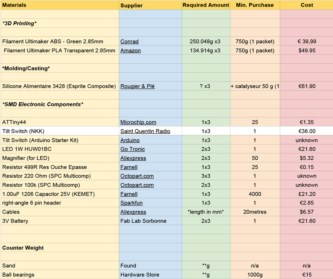
Parts & Processes
It will be necessary to print the buoy's 3D model in three separate pieces. The parts will then be assembled using threads. I will use Fusion 360 for 3D modelling and an Ultimaker 3 for printing.
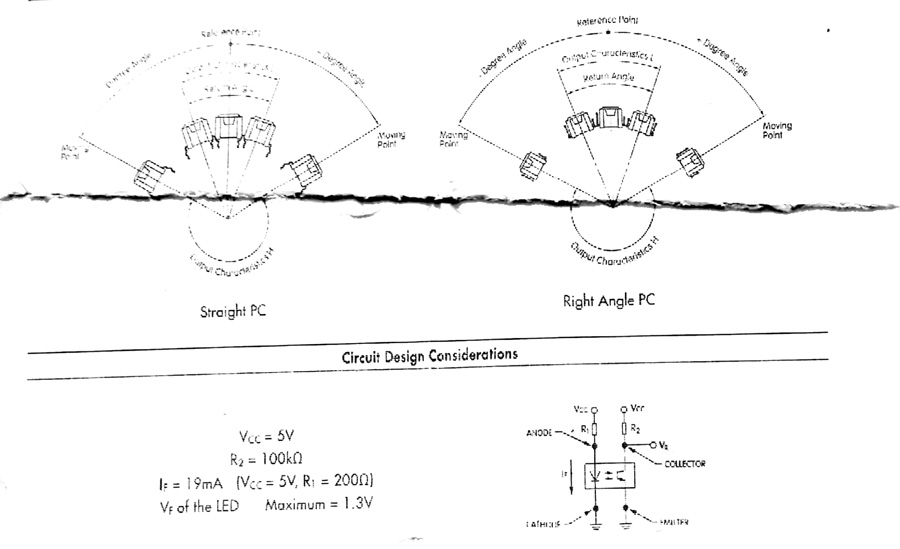
On the electronic side, I will need to combine aspects of the input (tilt switch) and output (RGBLED) boards I previously created – The tilt switch will react to the buoys movement and turn on a light at the base. I will use Eagle, Photoshop, Fabmodules, and an SRM-20 to create the board. A Best 936A soldering iron will be used to solder components to the board.
The lights will be connected with to the pcb via wires and run down to a dedicated lighting area. I will need to consider the position of these wires and making them hidden. The lighting should be well positioned (and magnified) so that it emits in an 'open' direction from the buoy.
I will need to make sure the micro-controller I select matches the number of pins required. There will be a certain amount of testing to see if the buoy's movement can be covered by just one tilt switch or if more eg. for x/y-axis, are required.
The remaining item is the electronic housing – I will mold a disc shape which will sit snug into the 3D printed parts and provide protection for the pcb board.
When the parts are assembled, I will need to apply sand to the base in order to vary it's movement and stability.
Questions to be Answered
- How freely does the buoy move and what effect does this have on the tilt switch
- How can adding sand to the base improve the situation
- How many pins do I need on the buoy's micro-controller
- How should the board be layed out to combine input and output devices
- How should the wires, lights and magnifier be positioned in the base.
- What dimension should the electronic housing be
Evaluation
The best way to evaluated the project is in use. Asking two people to play the triangle game around the buoys and observe impact. I am doing my best effort to create three buoys for 20th June. If only one is created, the project could be assessed by a variation of the game - passing as close as possible to one buoy without touching. This would also result in impact from time to time.
I continued work on my final project in week 19.