WEEK 8: EMBEDDED PROGRAMMING
Objectives
Group assignment:Have I...?
PROGRAMMING MY BOARD
So, the time to the time to do something with my board (see Week 6) has come. For this week I have decided to proceed with the following schedule:1 - Make a C code to blink the LED
First of all I tried to understand better what kind of file and tools I'll need and what they will do. Basically I'll use:I opened the Makefile found for Week 6 (Link) and tutorials in the Tutorial Section of Fab Academy's website in order to understand better how to build my own one. I admit that this required some hours of study, as well as some in-depth studies gived me by Simone Guercio. But in the end I decided to open the Makefile i linked before and modified it. Some information to include in this file are explained in ATtiny44 datasheet, like other as:
    #Project: week08 fab academy 2018
    #Author: Dario Bernabini, Santa Chiara Lab Siena

    PROJECT=blinkLEDario
    SOURCES=$(PROJECT).c
    MMCU=attiny44
    F_CPU = 20000000

    CFLAGS=-mmcu=$(MMCU) -Wall -Os -DF_CPU=$(F_CPU)

    $(PROJECT).hex: $(PROJECT).out
	   avr-objcopy -O ihex $(PROJECT).out $(PROJECT).c.hex;\
	   avr-size --mcu=$(MMCU) --format=avr $(PROJECT).out

    $(PROJECT).out: $(SOURCES)
	   avr-gcc $(CFLAGS) -I./ -o $(PROJECT).out $(SOURCES)

    program-usbtiny: $(PROJECT).hex
	   avrdude -p t44 -P usb -c usbtiny -U flash:w:$(PROJECT).c.hex

    program-usbtiny-fuses: $(PROJECT).hex
	   avrdude -p t44 -P usb -c usbtiny -U lfuse:w:0xDE:m
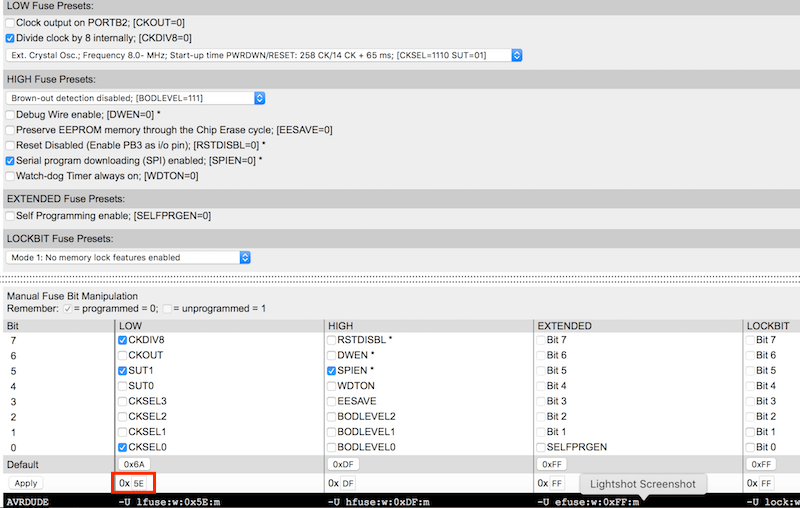
To be honest, initially I've set avrdude -p t44 -P usb -c usbtiny -U lfuse:w:0x5E:m in program-usbtiny-fuses and 1000 ms delay in my C file. But I notice that in this case 1000ms ≠ 1sec but around 10 seconds. I asked some infos to Simone that suggested me to take a look to This tutorial. It says:
The clock speed therefore is 1Mhz, i.e. if we tell the compiler in the Makefile with F_CPU = 8000000 that the chip runs at 8MHz, everything will be executed 8x slower than we expect. This is the explanation if delay_ms(double) seems ~10x slower against wall-clock time.Infact LOW Fuses bytes are, in general, responsable for clock and frequences; HIGH Fuses for (in general) for the communication with memories (flash, EEPROM), with the bootloader and with other devices via SPI.
So I Googled "ATtiny 44 fuses calculator and I opened This Website. I wrote 0x5E in LOW tab and Apply it.
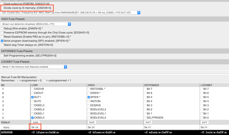
I've notice the tick on Divide clock by 8 internally; [CKDIV8=0]. Unticking that voice, the hex value changing in 0xDE.
So I opened again the datasheet and at page 24 I've seen:
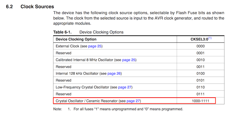
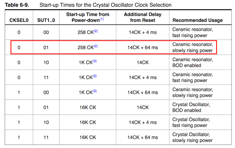
so, for Crystal Oscillator / Ceramic Resonator option, bit CKSEL3 must be 1, and others (CKSEL2, CKSEL1, CKSEL0) could be 1 or 0. Going ahead, at page 27:
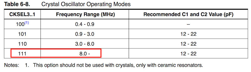
the datasheet says that for frequencies of 8 MHz or higher CKSEL3, CKSEL2, CKSEL1 must be 1. About CKSEL0, SUT0 and SUT1 bits:
And about CKDIV8:
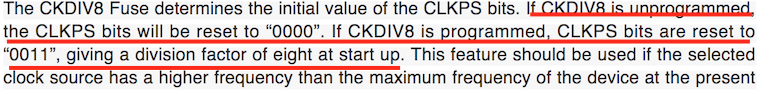
Returning for a second time to the Calculator and ticking or unticking bits in the method I've found in the datasheet, the result is also 0xDE.
PAY ATTENTION when you tick or untick options in this calculator because Tick = 0 = programmed and Untick = 1 = unprogrammed.
So finally, I'm sure that changing the low fuse value from 0x5E to
0xDE I could regulate the fuse and make 1000 ms exactly 1 second.
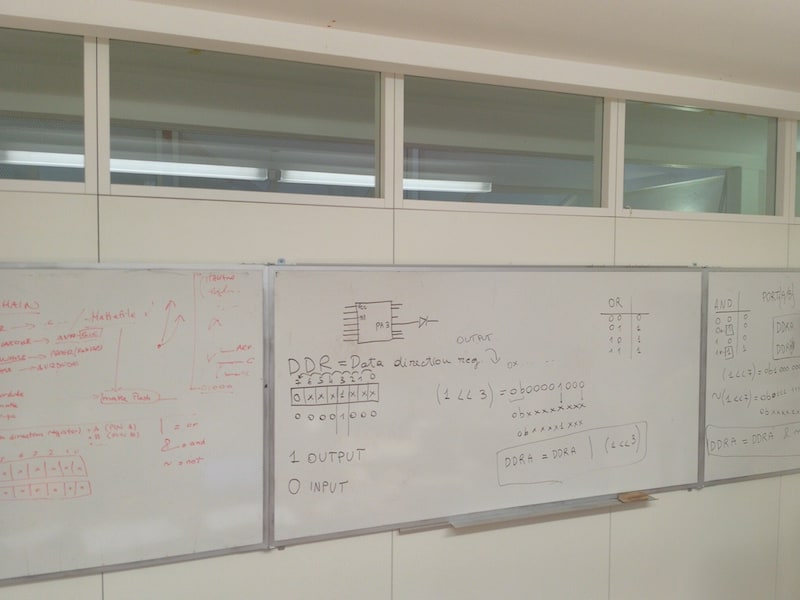
And here my C file. I admit that I wrote it looking some codes founded online, some made by Fab Academy students and some shared as example by the book Make AVR Programming (here the example). To make it I asked help to my classmate Tommaso, who explained me some informatic basic infos like logic operators in C language:
&=and
|=or
~=not
#include <avr/io.h>       //lib included
#include <util/delay.h>   //lib included

int main (void){                //start main function
    DDRB |= (1 << PB2);         //set 1 (output) to PB2 pin

while (1){                      //start infinite loop
    PORTB |= (1 << PB2);        //set PB2 in HIGH state (on)
    _delay_ms(2000);            //wait
    PORTB &= ~(1 << PB2);       //set PB2 in LOW state (off)
    _delay_ms(1000);            //wait
}

return 0;                       //exit main function
}                               //end
So I connected my programmer made during Week 4, I opened a new Terminal app inside the folder where I saved my blinkLEDario.c and blinkLEDario.make and I launched:
make -f blinkLEDario.make
in order to create blinkLEDario.hex and blinkLEDario.out, and
make -f blinkLEDario.make program-usbtiny-fuses
make -f blinkLEDario.make program-usbtiny
to start programming process. The result is:
2 - Make an Arduino code to blink the LED
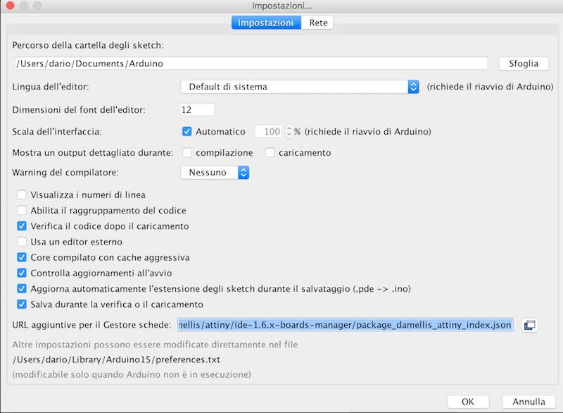
First of all I installed the Arduino IDE and, after opened it, I prepared it to communicate with other AVR boards. Adding this repo (https://raw.githubusercontent.com/damellis/attiny/ide-1.6.x-boards-manager/package_damellis_attiny_index.json) in Arduino Preferences (in MacOS) I could interface Arduino IDE with my board and other AVR microcontrollers (adding the support clicking inTools - Board).
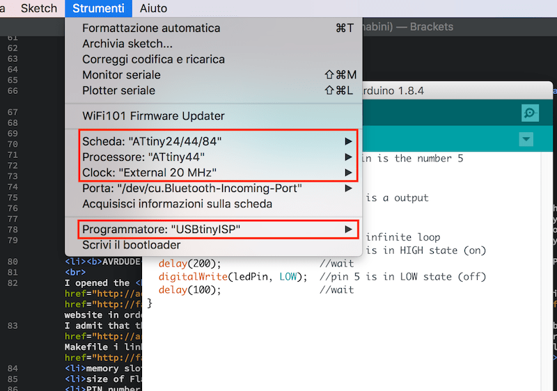
Than I choosed following parameters for communicate with my board:
      //DON'T COPY THIS CODE, IT'S WRONG!
int ledPin = 5;                 //PB2 pin is the number 5

void setup() {
    pinMode(ledPin, OUTPUT);    //pin 5 is a output
}

void loop() {                   //start infinite loop
    digitalWrite(ledPin, HIGH); //pin 5 is in HIGH state (on)
    delay(200);                 //wait
    digitalWrite(ledPin, LOW);  //pin 5 is in LOW state (off)
    delay(100);                 //wait
}
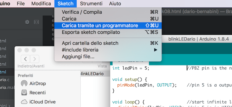
Once I finish, I clicked on Sketch - Upload via programmer
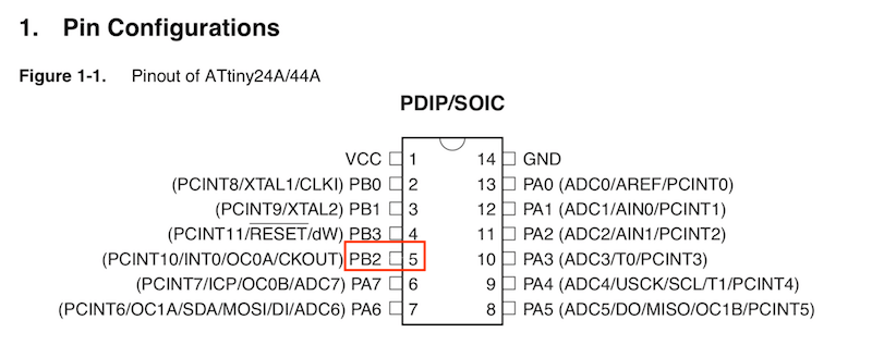
The result is that Arduino uploaded correctly the sketch but unfortunately nothing happened. I also thought about recognition problems about serial ports (I had heard of issues of the Arduino IDE on MacOS High Sierra). Looking better the only solution was that I declared a wrong PIN number. I choosed the 5 because I've seen it in the ATtiny44 Datasheet:
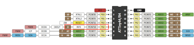
But it's wrong because Arduino uses different numbers for pinouts, infact searching for "ATtiny Arduino pinout" on Google I've found this scheme:
So I tried again and here is the result:
int ledPin = 8;                //PB2 pin is the number 8

void setup() {
    pinMode(ledPin, OUTPUT);   //pin 8 is a output
}

void loop() {                   //start infinite loop
    digitalWrite(ledPin, HIGH); //pin 8 is in HIGH state (on)
    delay(2000);                //wait
    digitalWrite(ledPin, LOW);  //pin 8 is in LOW state (off)
    delay(1000);                //wait
}
3 - Make a C code to blink the LED when the button is pressed
At this point I take my previous code and I try to modify it in order to swith on the LED when the button is pressed.
#include <avr/io.h>             //lib included
#include <util/delay.h>         //lib included

int main (void){
      DDRB |= (1 << PB2);             //LED on PB2 pin is an output
      PORTB &= ~(1 << PB2);
      DDRA &= ~(1 << PA7);            //button on PA7 pin is an input
      PORTA |= (1 << PA7);

while (1){
if
      ((PINA & (1 << PA7)) == 0){     //if the button is pressed
      PORTB |= (1 << PB2);            //set PB2 LED in HIGH state (on)
      _delay_ms(2000);                //wait
      PORTB &= ~(1 << PB2);           //set PB2 LED in LOW state (off)
      _delay_ms(1000);                //wait
      PORTB |= (1 << PB2);            //set PB2 LED in HIGH state (on) again
      _delay_ms(2000);                //wait
      PORTB &= ~(1 << PB2);           //set PB2 LED in LOW state (off) again
      _delay_ms(1000);                //wait
}

else {
      PORTB &= ~(1 << PB2);           //else PB2 LED is on LOW state (off)

}
}
}
And obviusly I modified my Makefile with the name of my new file:
PROJECT=blinkLEDario_button
4 - Make an Arduino code to blink the LED when the button is pressed
As last thing I've tried to reproduce the same behaviour using the Arduino IDE. I opened again my sketch created previusly and I started modifying it adding a button as an INPUT device. I must thanks Pietro and my classmate Tommaso for suggesting me.
int ledPin = 8;                         //PB2 pin is the number 8
int buttonPin = 7;                      //PA7 pin is the number 7
int buttonState;                        //buttonState variable

void setup(){
   pinMode(ledPin, OUTPUT);             //pin 8 is an OUTPUT
   pinMode(buttonPin, INPUT);           //pin 7 is an INPUT
   digitalWrite(buttonPin, HIGH);       //activate button internal R-pull
}

void loop() {
  digitalWrite(ledPin, LOW);            //initial LED state (off)
  buttonState = digitalRead(buttonPin); //button state is given reading the button pin

  if(buttonState == LOW){               //if button is pressed (it's connected to GND)
   digitalWrite(ledPin, HIGH);          //LED is switched on - here I could add a delay to blink it
  }

  else{
  digitalWrite(ledPin, LOW);            //in every other cases LED is switched off
}
}
Download and Conclusions
I'm very far to say that I learned C and Arduino codes (I think one week it's a very short time), but the work made during this week it's a little start. It was very hard undersand first the logic behind bits position in DDR and PORT registers and translate them in my C code. It's clear and I know that I have to learn more and more.Question about datasheet? A lot. Quite every single word and figure.
As last thing I would compare sizes of my last two codes:
--> Download week8.zip (ZIP Archive, 11 KB)
Arduino Dictionary
In order to understand better commands, variables and logic operators in the Arduino environment, I decided to make a sort of very basic "Arduino Dictionary" that I think it could be useful in the future.Structure
Constants
Variables
Control structures
Comparison operators
Input and output functions
Time functions
EXTRA - Satshakit
I also tried to create a new board, in particular the Satshakit. It's basically an homemade Arduino board and infact Arduino IDE recognize it as an Arduino Uno.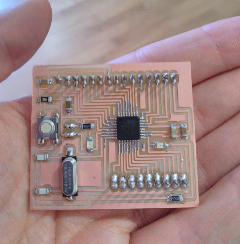
The only thing I modified is that the crystal I've found in my Lab is at 16 MHz but it needs two 18 pF capacitors instead of 22 pF suggested by the creator of Satshakit in his BOM.
Once I finished I tried to burn bootloader via Arduino IDE and...obviusly for the third time...rc=-1!
In the last month I've seen more rc=-1 messages than "how are you?" SMS from my mom.I solved the problem with a second soldering, adding some tin around headers. And than finally it worked but......with some problem about timing (in particular, a delay(1000) were around 0.5 second), using the code:
int ledPin = 9;           //PB5 pin is the number 9

void setup() {
    pinMode(ledPin, OUTPUT);
}

void loop() {
    digitalWrite(ledPin, HIGH);
    delay(2000);
    digitalWrite(ledPin, LOW);
    delay(1000);
}
I thought about two possible causes:
I left the hardware option as last and least option and then I decided to focus my attention on the software. Continuing not to see anomalies in the sketch (Arduino IDE compiled it and sent it without problems), I came to the conclusion that there was a strange management of low fuses, caused by the use of a external crystal (remember this words). So I opened the boards.txt file located in
Applications - Arduino - Contents - Java - hardware - arduino - avr for know how it manage fuses.
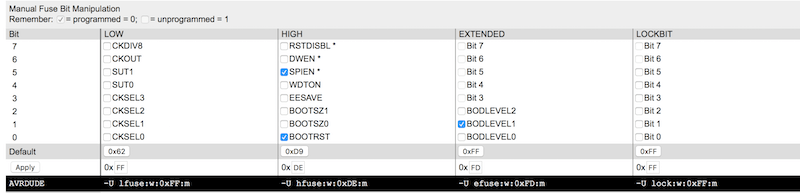
uno.bootloader.low_fuses=0xFF
uno.bootloader.high_fuses=0xDE
uno.bootloader.extended_fuses=0xFD
So I opened again the AVR fuses calculator, I inserted hex values of Arduino Uno fuses and I saw what happened:
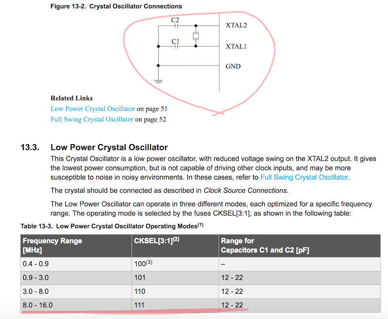
Hoping to find the truth on the matter I opened the ATmega328P datasheet. I went immediately to page 58 because I thought I was in the situation of an external clock source. Here I found that CKSEL [3:0] fuses must be programmed, so 0000, a situation already so different from the one I started from. Coming back to AVR fuses with these new values, happy that we have found a possible solution to my problem.
Arrived at this point however, Simone completely disassembled my theory with the simple phrase
"Look, you don't have external clock sources! You haven't to intend the crystal as an external source: it is an external source when your 328p is connected to other microcontrollers or other sources of calculation. You are in the situation described on page 51. Arduino IDE has not made any mistakes at all, DUMB!".
OK, Arduino IDE made everything right...but where is the problem???
Who of you chews on economics or cognitive psychology will have surely heard of the heuristics of availability. It is a situation in which people tend to overestimate unlikely events, which can be summed up in the phrase "if you hear noise of hooves and you're in Italy, are more probabile to be horses, not zebras".
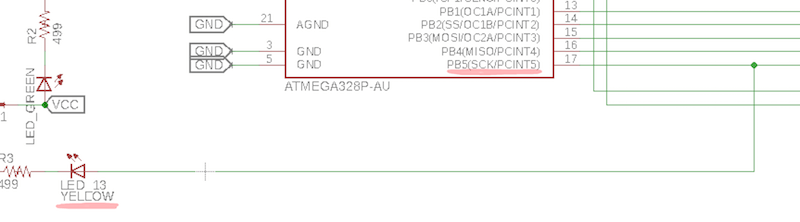
In this case I thought it was more likely that there were problems with the IDE arc rather than that I had simply misplaced the sketch. There was no conspiracy, no clamorous problem, simply pin PB5 is not the number 9 of the pins of Arduino, but the 13!
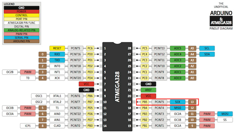
I don't really know why I wrote 9 in my sketch! Probably I read quickly and confused 15 with PB5. DUMB2!
At least I used it to look at other values in the datasheet of another microcontroller and always to pay attention to each step, as such a trivial error has taken a lot of time away. Finally, uploading a sketch similar to:
int ledPin = 13;

void setup() {
    pinMode(ledPin, OUTPUT);
}

void loop() {
    digitalWrite(ledPin, HIGH);
    delay(2000);
    digitalWrite(ledPin, LOW);
    delay(1000);
}
I finally realized that my satshakit has no problems with solderinh, with timing and that the cable I built to solve this problem at home during the holidays is also works fine.