Electronics design
1.- Choosing my design
For this assignment I had to start by choosing my design. At the start I wanted to do a counter using an 8 segment LED display, but then I realized I could count all the way to 127 using just 7 normal LEDs. So I decided to use an Attiny 84, since it had several more pins, that I did not have to use to program it, to connect to a button, and 7 LEDs. For this I had to check the Data sheet for the Attinny. I chose the 84 because I was going to write the program with Arduino, so since I was not sure how much space it was going to use, I preferred to have space to spare, than a lack of it.
.jpg?crc=93862152)
2.-The design
I had to download the program EAGLE from the autodesk package. I have used this program once before, by insistence of my father on learning some of the programs used in digital production. To begin my design I had to make a schematic with the components I had to use and to know how to connect them.
.jpg?crc=3879027409)
.jpg?crc=4146248639)
After making my schematic I moved on onto making the board. It was the first time I made a board by myself, without the constant help of someone. I thought it was a pain to use normal ways of connecting the programming pins, so I just went my own way and used single pins and put them separate and next to the pin. Doing this on the Eagle program on my own made me see how useful the schematic is, because even though it restricts you a bit, you always know what to connect with what, because the program binds both the schematic and the board, so i t makes it easier to make a PCB.
.jpg?crc=168371970)
.jpg?crc=341565188)
After designing both my sketch and my board I had to export it as a PNG to mill it in the Modela, so I had to experiment on how to export it and ended up with a lot of images (which I later deleted) in my project folder
.jpg?crc=253186566)
3.- Milling and soldering
Once I had exported the images, I went to the Modela and pasted my copper plated board, in order to mill the circuit. Unfortunately, the sacrificial bed was too used, so the board moved before finishing the milling process, so I had to replace the sacrificial bed and mill it again.
.jpg?crc=513016974)
.jpg?crc=81467304)
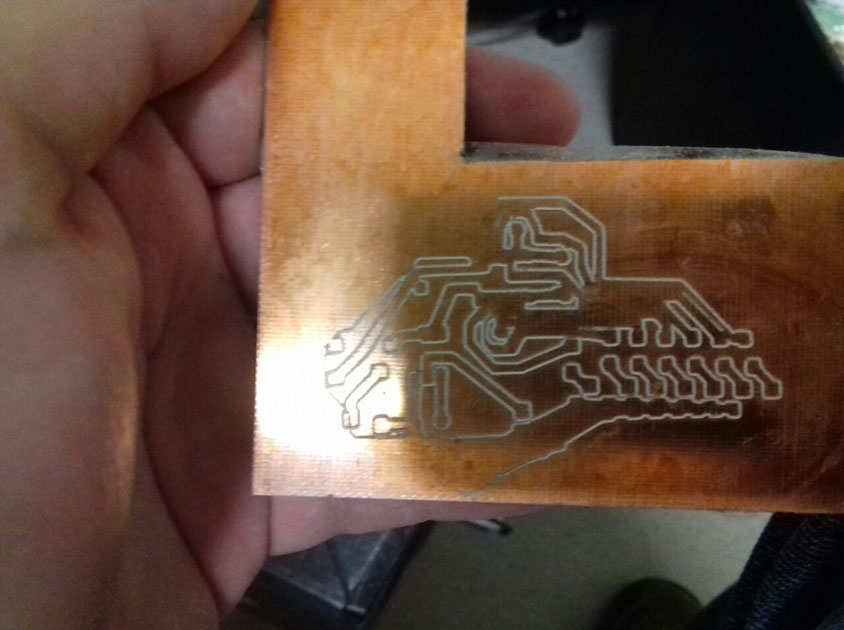
.jpg?crc=3871089916)
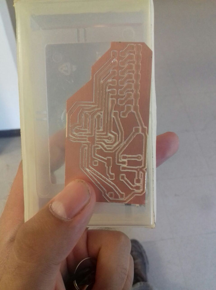
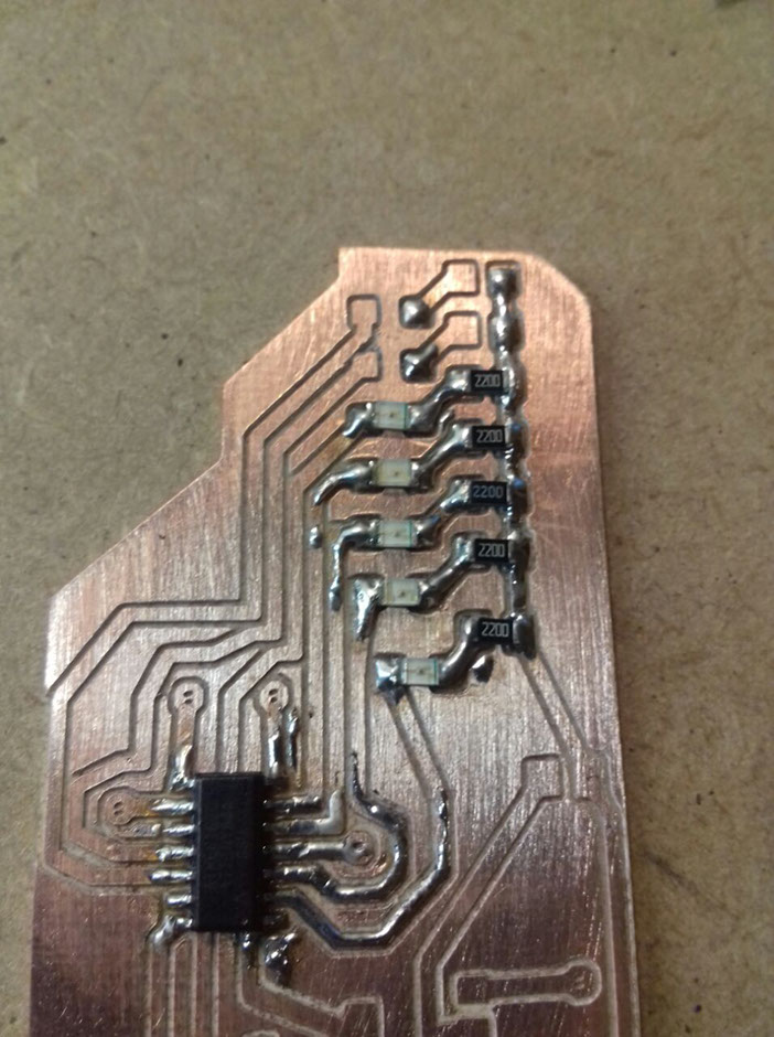
After this minor upset, I ended up milling my complete board in another plate. The components I had to solder are the following:
- 7 x 220 ohm resistors.
- 4 x Red LEDs.
- 3 x Green LEDs.
- 6 x Individual pins.
- 1 x Attiny84 .
- 1 x Button.
- 1 x 10k ohm resistor.
- 1 x 0.1 Micro farads capacitor.
- 1 x 5v regulator.
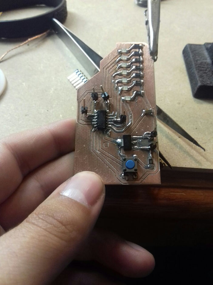
I proceeded to solder them and feel happy about my work. Except for a small accident I had with the solder, I put a bit too much, and now I have a small piece of the board coated in solder. a small square not connected to anything is noticeable in the pictures, I decided to put it as a mark to know how to position the Attiny.
The compressed folder with the files I produced can be downloaded here.