Week 5: Electronics Production
Group assignment:
Characterize the specifications of your PCB production process.
Individual assignment:
make an in-circuit programmer by milling the PCB,
then optionally trying other processes
For this week's task, started up by making the milling files for the board in the net, in fabmodules.org using Brian's files
Traces (1000 dpi)
Outline Cutout (1000 dpi)
In the site, use the traces file first, selecting it from the image menu. Next, select machine, which is Roland mill. Then, PCB traces (1/64). From side, change model to match your machine. We had SRM-20. Next, move origin to x0,y0,z0 (default is x10,y10,z10). Change the cut depth to your liking. We used V-shaped tool, which diameter changes by how deep it cuts. The deeper cut means wider. Tool diameter option should match the depth and wideness of the V-shape tool, otherwise calculations might go wrong. I used the tool diameter of 0.4 mm and cut depth of 0.12mm. Repeat the process for outline, but select PCB outline (1/32) from 3rd menu, and change tool diameter to match the tool. We had 1mm tool for the outline.
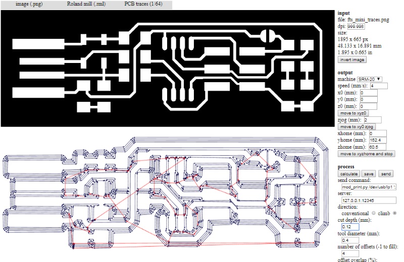
After calculations, check the images. If they look OK, save them and move to the milling part.
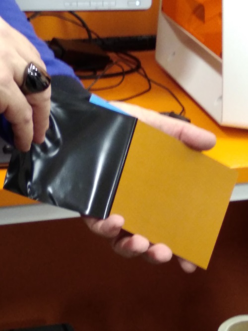
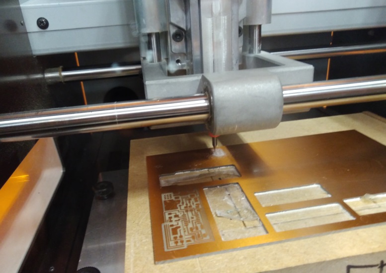
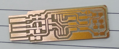
Setting up the mill. Make sure the milling platform, the sacrificial wood and millable board on it are perfectly level. Use doublesided tape to keep the board still. We used FR-1 board, so had to remove the protection for photo sensitive layer.
Change the milling bit. Use allen key to loose the screw on the milling bit, then pull it out. Insert the tool you want to use and push it as high as it goes. Then tighten the screw.
Set the tool position from the software. Use +/- X/Y arrows from middle to move the milling bit to right position. Then set it from right, "set origin point" and click X/Y. Next, move the milling bit in z-axis closer to the board. When it is close enough, manually loosen the screw and gently lower the milling bit to surface of the board and tighten it there. Again, under the "set origin point", click Z this time. After that, from setting panel, lift the z-axis up a bit.
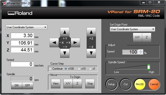
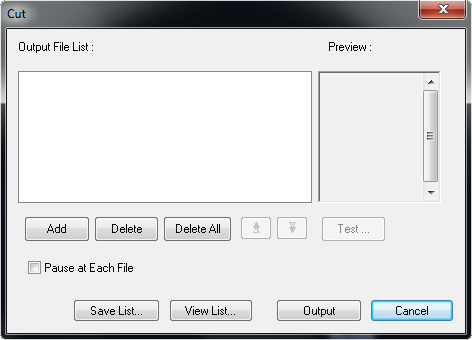
When everything is set, hit cut button. If there is any file from previous user, delete all. Click add and find the file you want to mill. Finally, click output to start the mill.
My files:
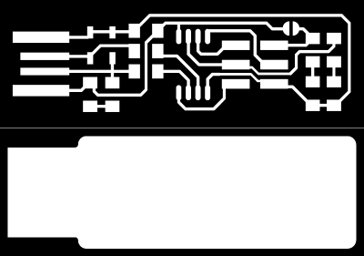
Traces
Outline
Time to wait for the mill to do its job...
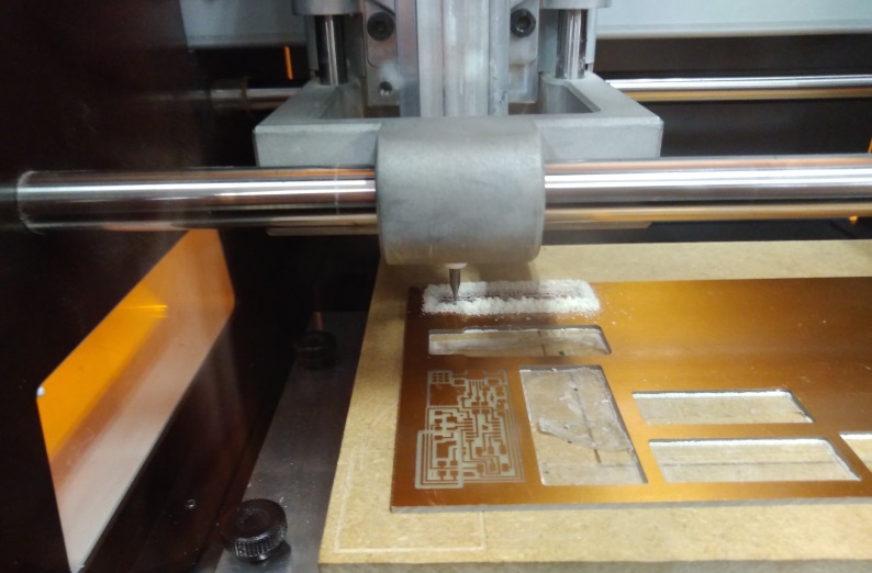
Next change the milling bit to 1mm cutting tool. Find Z-axis board surface spot for the new tool. Delete previous files from cut and add outline file. Hit output. Wait again.
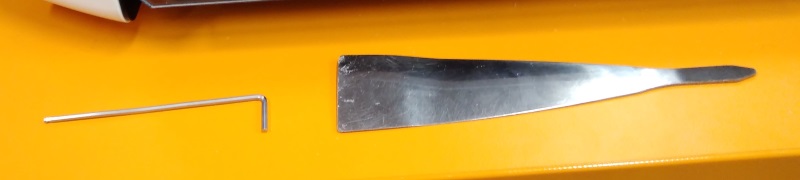
Tools used; Allen key for changing the milling bit and spatula for taking out the milled board from its hole. Was surprisigly hard since it was taped in so firmly.
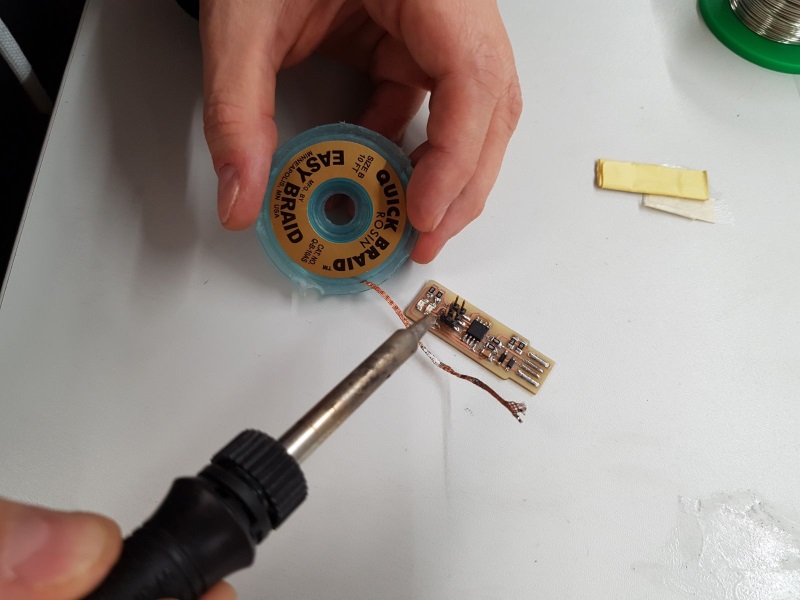
Last bit before soldering was to remove photo sensitive layer with steel wool, and few bits of copper with a knife.
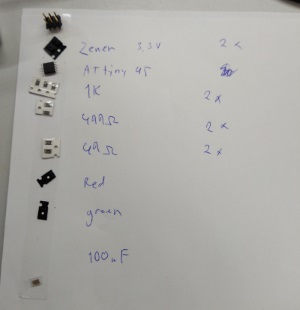
About to start soldering the board. Firstly grabbed the components from storage. Made "shopping" list with tape as suggested.
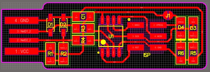
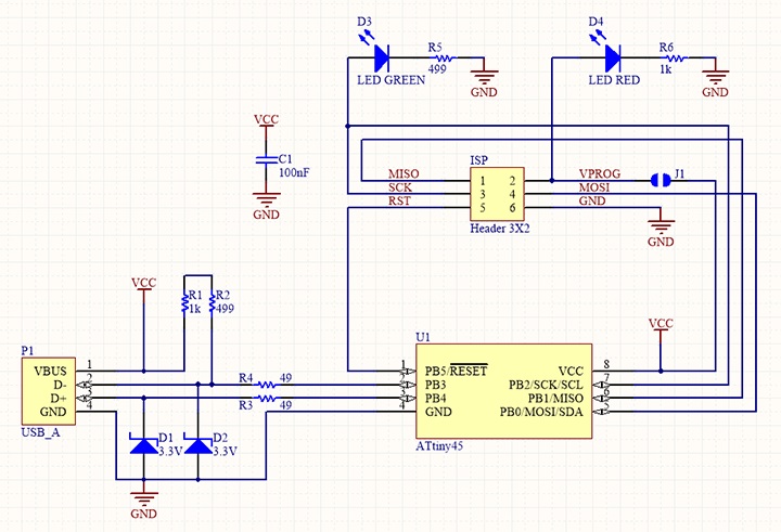
Then opened up brians page again to see where to put the components. I'll put the images here too.
After I had everything ready, I went for it.
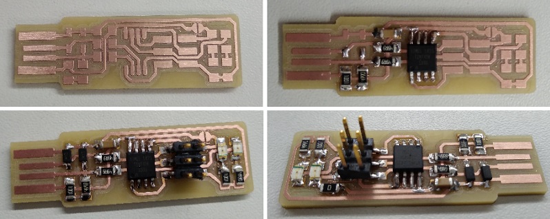
At this point I hear its customary to check with multimeter that Vcc and GND are not connected. Quickly checking that one out and they were not.
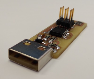
Programmed the board too. For setting up the process for windows, I followed this guide, credits goes again to Brian. Downloaded firmware source code and run make in bash and generated my hex file.
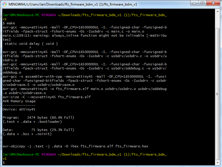
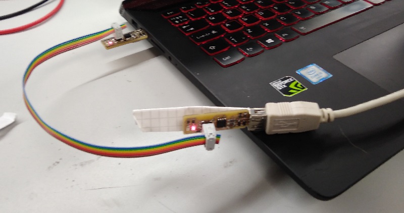
Checked the makefile for PROGRAMMER ?= usbtiny since it was another FabISP I was using. Connected the boards, had to put some paper in for mine, so the usb would stay firmly attached. Got red light, which in this case means go.
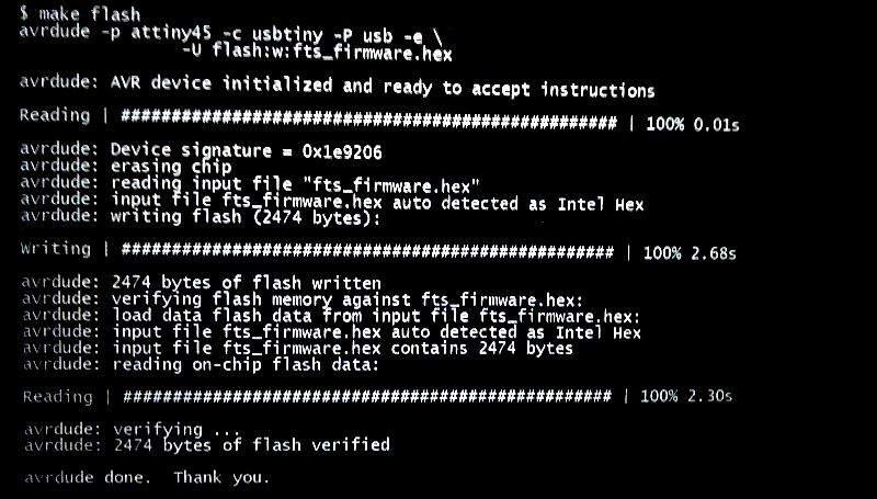
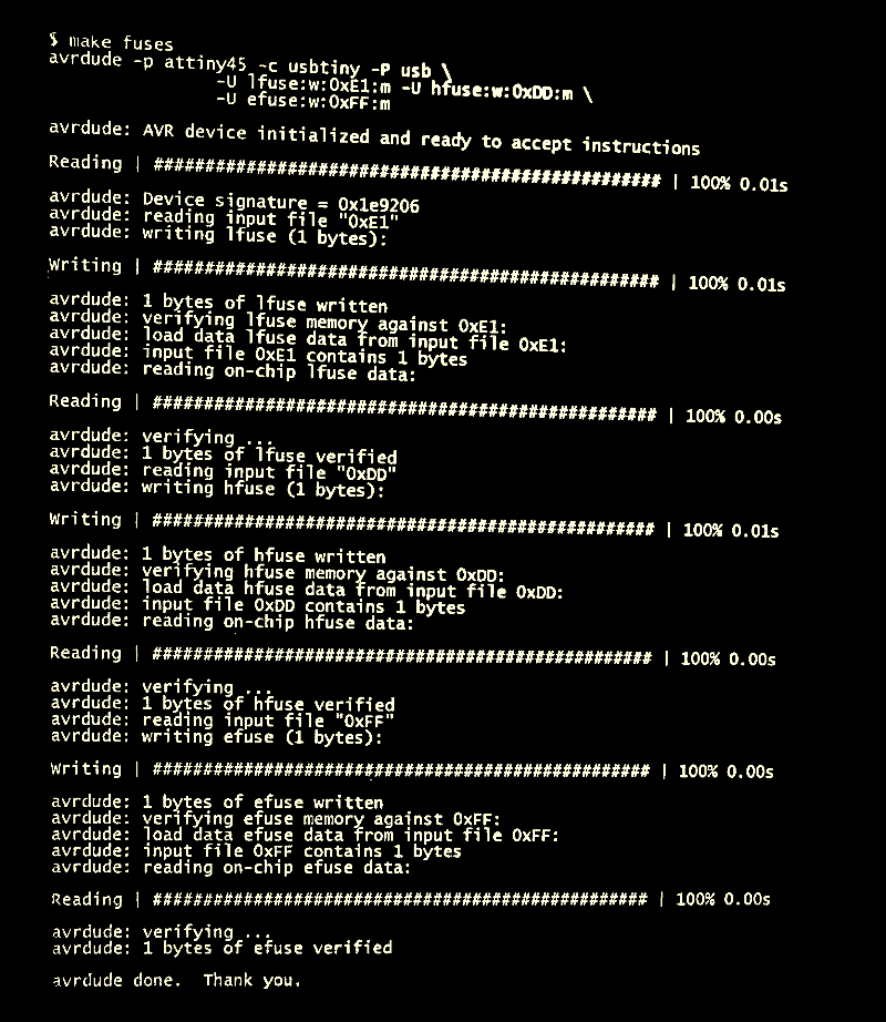
Make flash. This will erase the target chip, and program its flash memory with the contents of the .hex file.
Run the make fuses command. This will set up all of the fuses except the one that disables the reset pin.
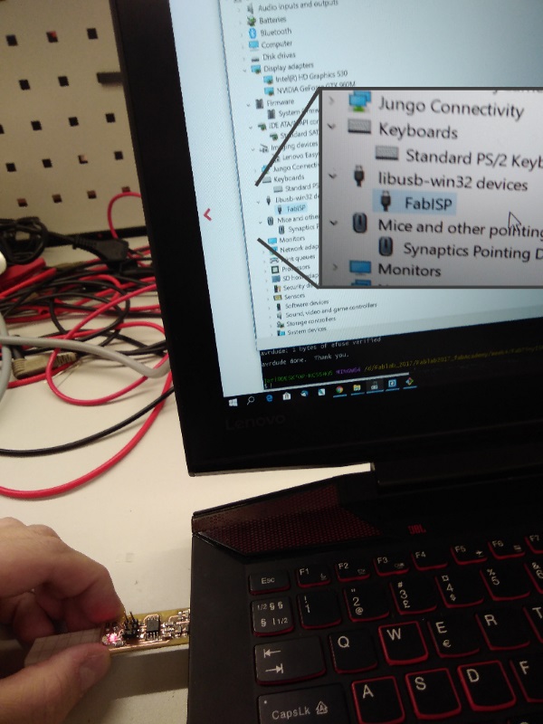
Testing the board. Removed all and plugged my board to the usb, stuffed with paper for better connection.
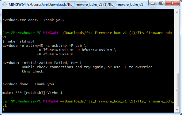
It works! At this point I thought I was done and started doing documentation. And in the end I noticed there was still one more command to run, and that was make rstdisbl.
For some reason, it kept giving me error message about connection. I did have my own laptop though, and previously I had used one of our instructors.
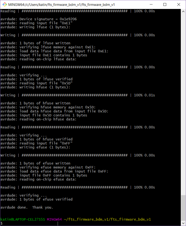
One my classmates, Kati, managed to run everything just fine, and she was kind enough to allow me to try my board with her setup and it worked!
And now to remove the jumper.
Since the connection between my board and computer wasnt good, and I wanted to get rid of all MacGyvering with paper, I thought I'd use an USB connector from old mouse.
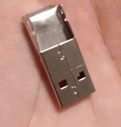
I used a metal saw to get rid of the excess material, and super glued the remaining of the USB connector to my board. Works like a charm!
Group assignment
For possible group assignments, our groups vary with how each of us can participate that week. For this week, it was me, Ari, Kati, Marta and Behnaz, and our group work can be found here.