Final Project: Remote Game Controller
Quicklinks:
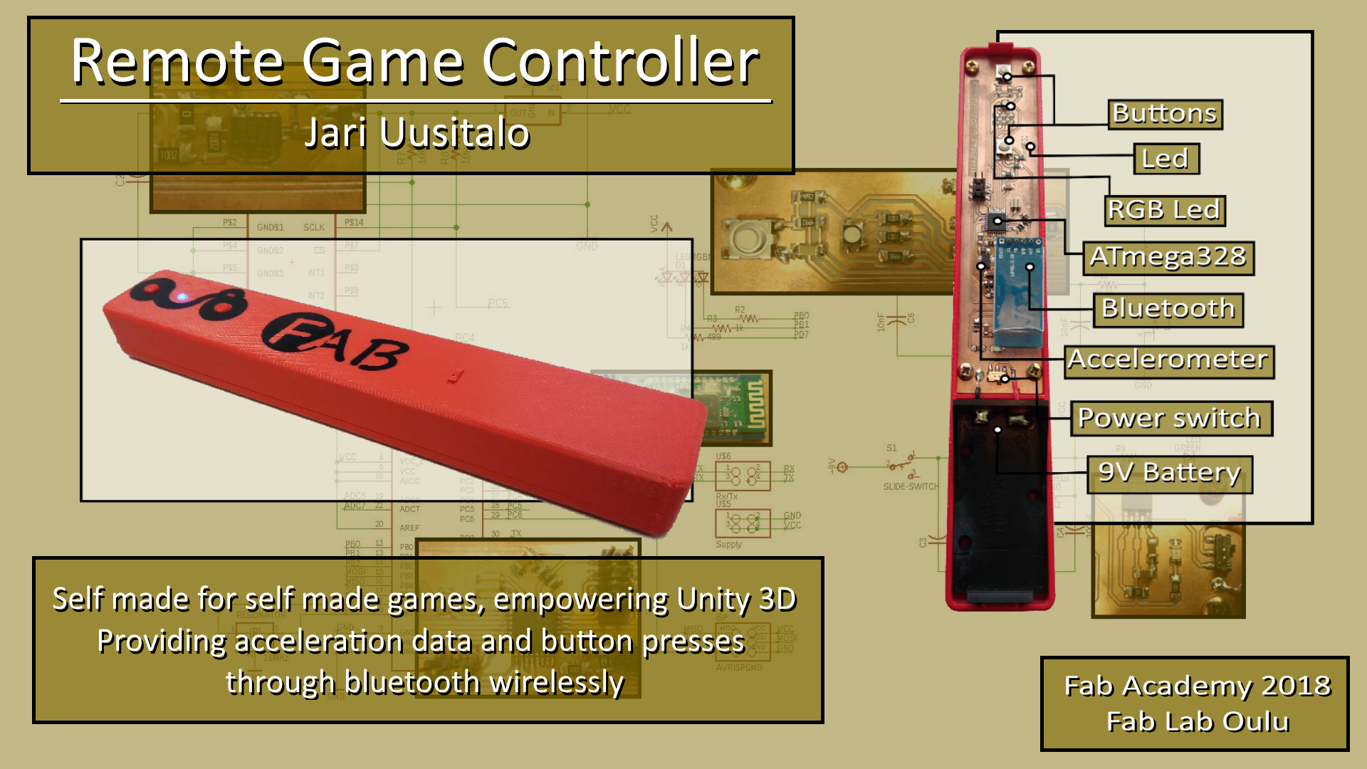
presentation SLIDE
presentation VIDEO
Table of Contents:
Initial Idea: Flying Tray
Alternate idea: Light Switch
Remote Game Controller: Initial thoughts
Designing the board
Milling
Soldering
Designing the Case
Printing the case
Assembly
Decorations
Embedded Programming
Making the Interface
Bill of Materials
License
Slide
Video
Files
Initial Idea: Flying Tray
At first week, we had to plan our final project and I came up with an idea of a flying tray. I've never had any flying things and looking up from the internet, drones look really nice and fun.
So basicly its a drone, and drones carry stuff, usually below them or integrated on their structure, like cameras. This one should carry stuff ABOVE, and with light, flat frame it should work indoors.
Here is the sketch image from week 1: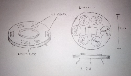
So who's it for and what can be done with it?
It could be;
Medical tray for elderly - pills fly to you by timer or when called.
Food tray - some light food, like salad flown to table in a restaurant.
Snack tray - potato chips are light, why not float those around in a party.
UFO - put some leds on it and make it spin. WEE!
Design
At week 3, we went through computer-aided design, I drew the deck of flying tray with Inkscape. Further on, I made a 3D model and render from that image with blender.
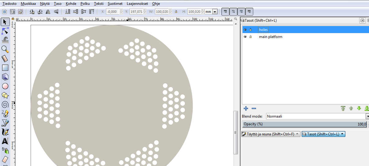
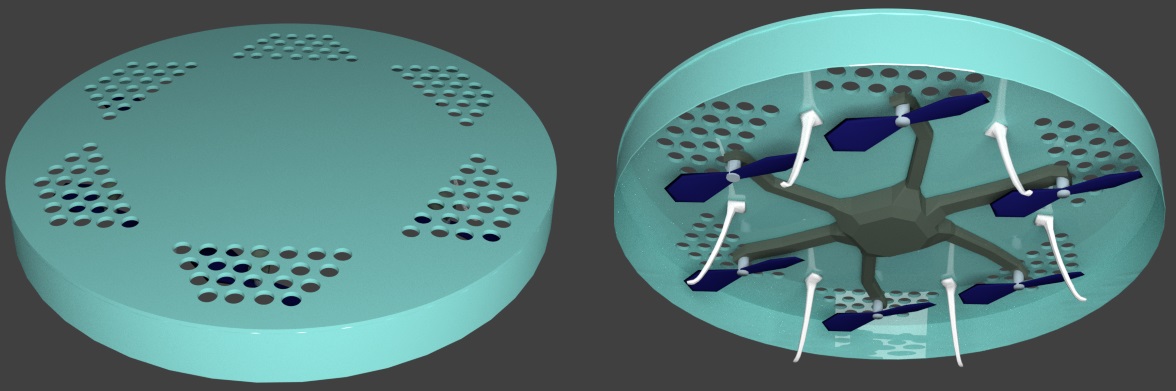
So far, it is an artistic image, but gives an idea where I'm going with this.
Alternate idea: Light Switch
Light sensor with synchronous detection x 10. Each result control LED luminosity. So if you move finger over the strip,light is brightest where finger is going, i.e. light follows the finger. When finger is removed, depending on the position in strip, that sets the level of room lighting.
Remote Game Controller: Initial thoughts
So this is it. Design board with:
- accelerations sensor
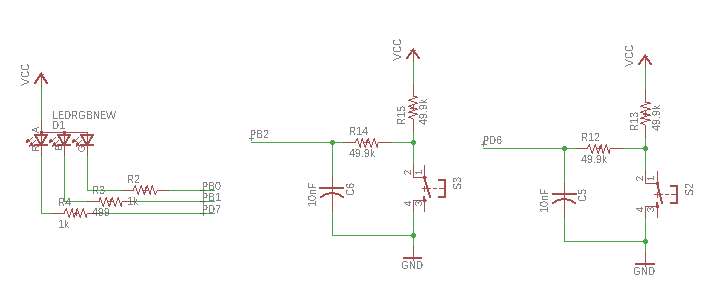
- few buttons(game controls, calibration)
- RGB/led for mode, calibrations, info...
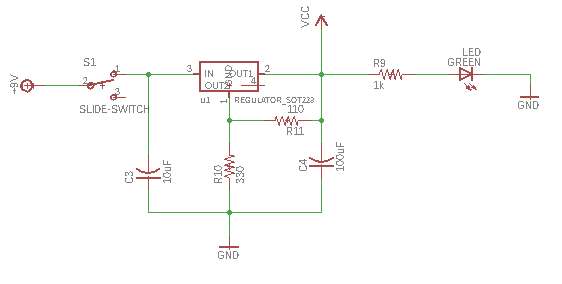
- regulator for battery power
- pins for bluetooth
- Atmega328P for space and pins
Casing can be made with 3D printing.
Small parts for transferring different position buttons pressing can be 3D printed or laser cutted.
Wireless communication with bluetooth master/slave pairing
Idea is to to make wireless, battery powered, hand held controller for self made games with unity 3D. It will take user input in form of a motion and button presses and wirelessly transfer that input to a computer, where it will be translated to commands.
It is meant for game programmers and designers, as an example and basis, that it is relativily easy to make a custom made controllers.
It will contain a PCB board, 3D printed casing and buttons, and a commercial bluetooth module
Processes used covered the following lessons:
- Electronic design and production.
- Embedded programming.
- 2D design (vinyl cutting for decorations, laser cutting for slide switch)
- 3D design and printing(case, buttons, mechanism)
- Input devices ( accelerometer, buttons)
- Output device (RGB and normal LEDs, Bluetooth)
- Interfacing (To make it work within Unity 3D)
For additional information, week 19, week 20 and week 21 covers alot in a form of short pages and simple questions.
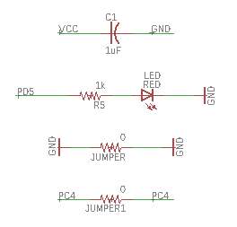
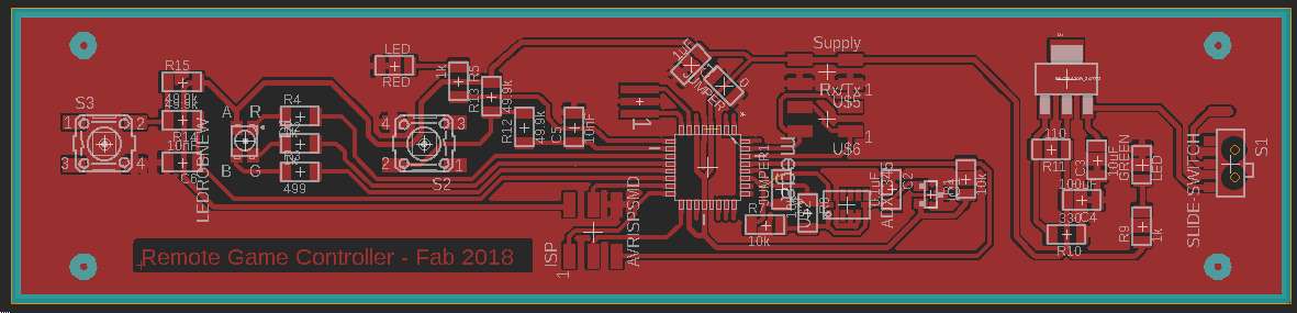
Designing the board
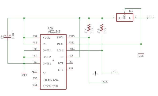
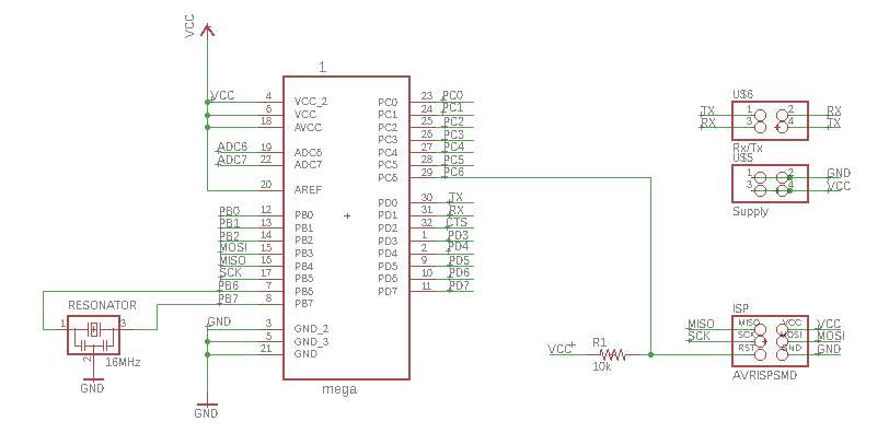
Used Autodesk Eagle in designing the board, as I had done previously, starting from week 7 . I decided to go with ATmega328P microcontroller, as it had sufficient amount of memory and leg pins. Also needed to take a look how to connect the accelerometer from ADXL343 datasheet.
I had planned to make an elongated design, so I placed the components accordingly. On the milling layer added extra holes for screws.
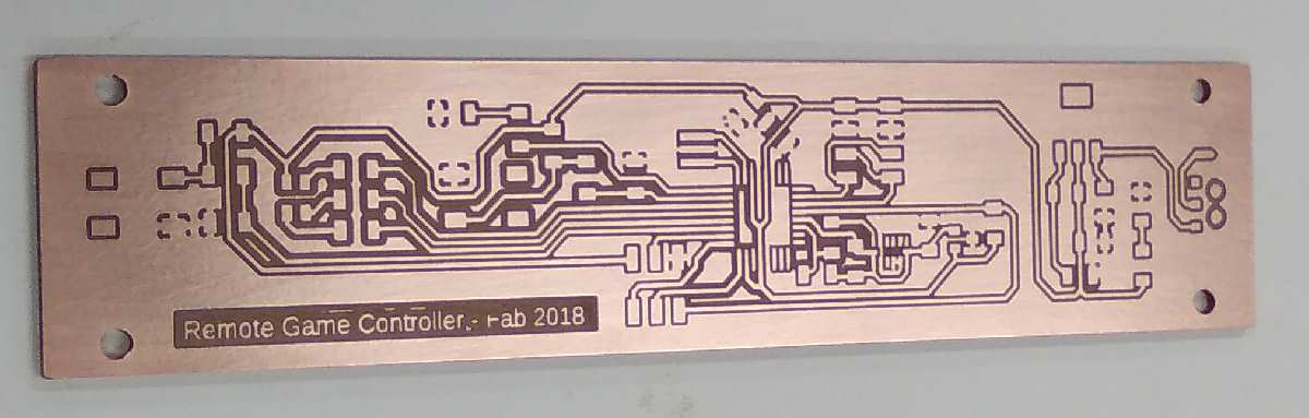
Milling
Used fabmodules.org to generate files for milling. Proceeded as done in week 5, with only notable setting difference that the cut depth was 0.09 mm and tool diameter 0.22 mm.
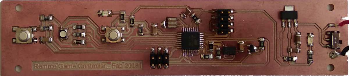
Soldering
Started to do soldering, as I had done previously, starting from week 5, and picked up the necessary components so I could test if accelerometer was responding correctly. Soldering accelerometer was not a regular soldering job, as it had only bottom pads, not side ones. I tinned up pathways below it, and applied bits of soldering paste used in reflow oven. Attached the accelerometer and then heated those pathways with soldering iron. After brief testing, it was giving out flat zeroes. So applied heat from heat gun, hoping it would help. The heat gun resulted some discoloration on the board but did the trick; the accelerometer was alive.
I then proceeded to solder the remaining parts, but after a visit at our storage, I realized we didnt have 330 ohm or 11 ohm resistors, as I had planned to use with 5V regulator. So I changed my plan, and went for simplified version of the regulator circuit, which had only two capasitors. I had to add a zero ohm jumper to make it work with the board I had. After soldering I quickly tested it with multimeter that there were no shorts.
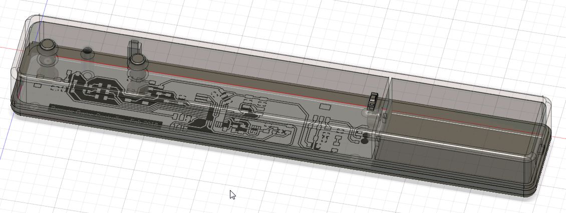
Designing the Case
Made my design with Fusion 360, as I had practised it many times before(weeks 4, 6, 8, 10 and 18). Whole design consisted of seven parts; top and bottom part of the case, two buttons and mechanics pieces for power switch. I used trace image from eagle as a canvas to ease out the designing.
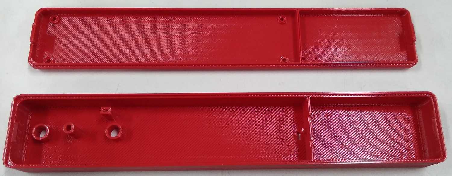
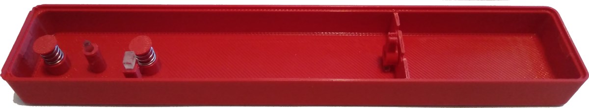
Printing the case
Made my 3D print with our Stratasys printer. Process was the same as week 6, though I changed visible surface style to enhanced, hoping for a cleaner result. As it came out, the finishing wasnt that much different from normal surface style. I think I need to make walls somewhat thicker, and then sand it manually if I want smoother results.
Assembly
I attached my board to the bottom part of the case with 4 screws and attached the battery case with glue.
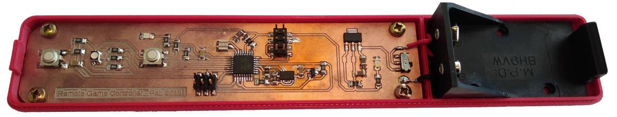
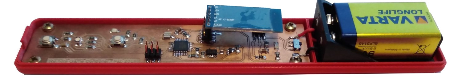
Put some springs on buttons, so it wouldnt sound like a maracass when moved. Used some scrap pieces of clear acrylic to make light pipes for the leds and used glue to attach them in place. Power button slide mechanism was too small, and broke when trying to assemble it. I made replacement parts from 3mm acrylic with laser cutter.
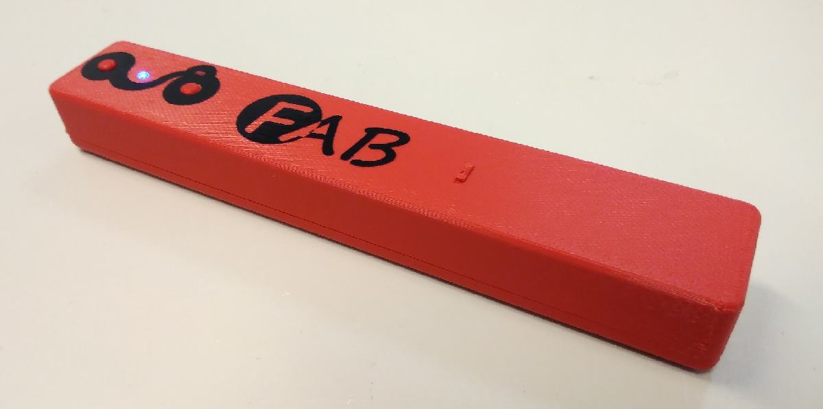
Decorations
For it not to look so plain, I cutted some vinyl for the decoration. Quickly drew some lines and circles with Inkscape, proceeded with vinyl cutting as was done in week 4. Applied the result.

Embedded Programming
After browsing around, I decided to go with Arduino IDE's Wire library, which allows I2C communications. Then I followed this guide, for setting up ADXL 345 acceleration sensor with arduino IDE.
In addition of acceleration data, I wanted to send status of two buttons, or rather, two modes(making modes widens options). The final "frame" contained 5 values in a form of a string; x, y, z, modeA and ModeB. This was done as previously, starting from week 9.
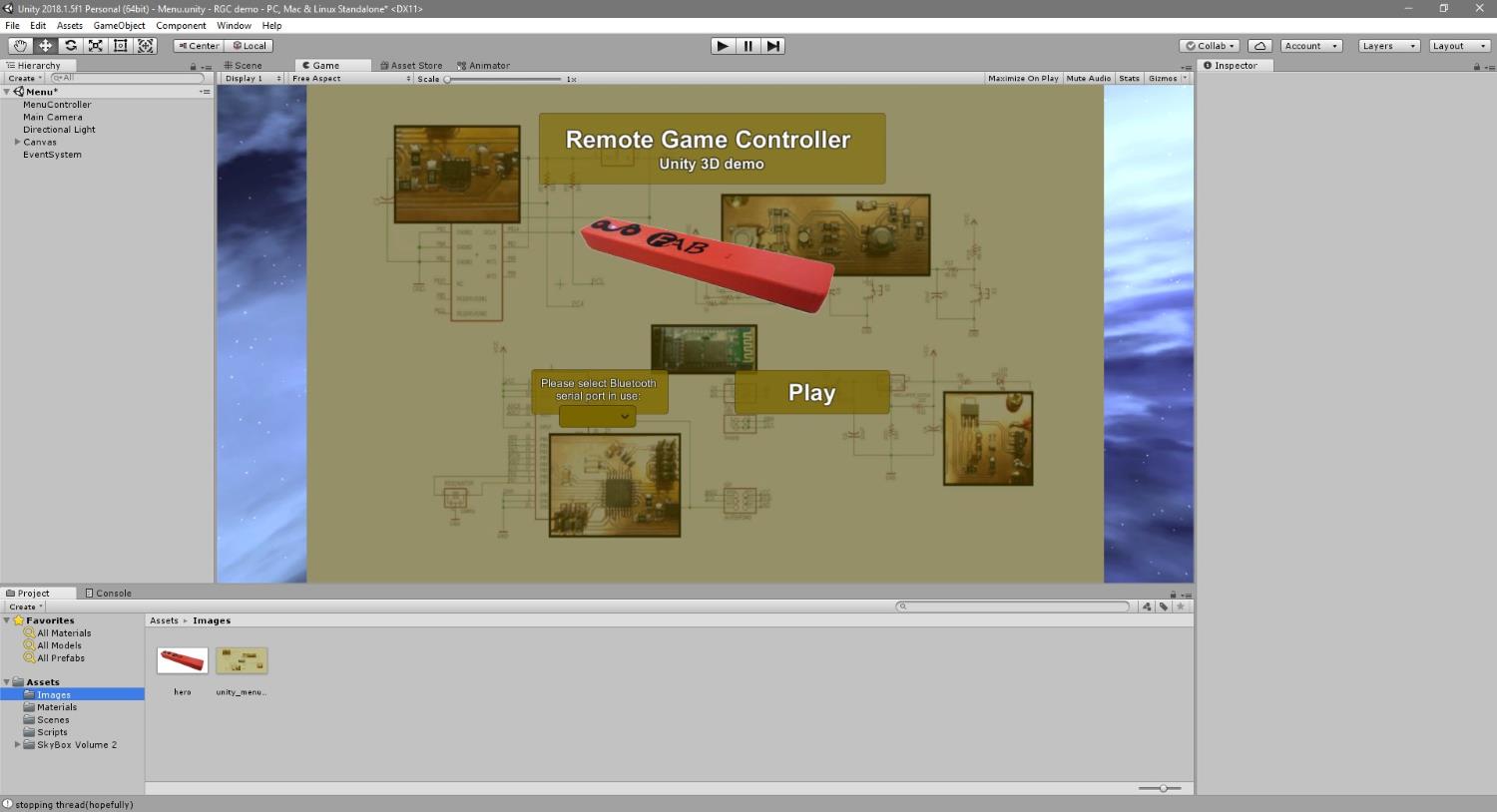
Making the Interface
Making the interface with unity didnt differ that much from week 14. I made a scene for port selection, though this time its not FTDI but Bluetooth COM port.
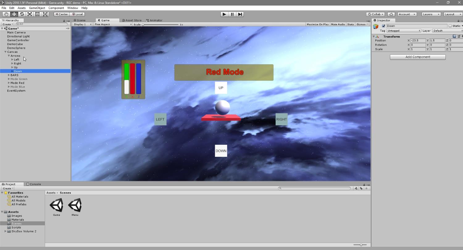
Then created another scene to visualize the values coming from serial line and from the game controller itself. Added free skybox to the scene from unity asset store to visualize a bit more. I started another thread which could handle reading the serial line and updating variables, so it wouldnt tax too much Unity UI's Update method. I had to average accelerometer data, since it was too spiky. Then it was smoothness versus lag and I had to find balance, which was average of 5.
On this scene, buttons cycled through modes. Upper button mode had 4 possibilites, and this was reflected with RGB led(1 for each color and all off) on the controller and corresponding text on the scene. Lower button just changed the displayed object. Acceleration values give straight position coordinates to the gameobject. I made some treshold values for reading swipes to left, right, up and down and added icons to reflect that. Those icons deactivate after 1 second, and during that second none of the others can be active.
Bill of Materials
| Part | Value | Device | Package | Description | Price |
| 1 | mega | ATMEGA328P-AU | 2.87 | ||
| BUTTON1 | 6MM_SWITCH6MM_SWITCH | 6MM_SWITCH | OMRON SWITCH | 0.74 | |
| BUTTON2 | 6MM_SWITCH6MM_SWITCH | 6MM_SWITCH | OMRON SWITCH | 0.74 | |
| C1 | 1uF | CAP-US1206FAB | C1206FAB | 0.07 | |
| C2 | 0.1uF | CAP-US1206FAB | C1206FAB | 0.12 | |
| C3 | 10uF | CAP-US1206FAB | C1206FAB | 0.04 | |
| C4 | 10uF | CAP-US1206FAB | C1206FAB | 0.04 | |
| C5 | 10nF | CAP-US1206FAB | C1206FAB | 0.04 | |
| C6 | 10nF | CAP-US1206FAB | C1206FAB | 0.04 | |
| D1 | LEDRGBNEW | LEDRGBNEW | P-LCC-4 | 0.60 | |
| IC1 | REGULATORSOT23 | SOT23 | 0.32 | ||
| ISP | AVRISPSMD | AVRISPSMD | 2X03SMD | 0.6 | |
| JUMPER | 0 | RES-US1206FAB | R1206FAB | Resistor (US Symbol) | 0 |
| JUMPER1 | 0 | RES-US1206FAB | R1206FAB | Resistor (US Symbol) | 0 |
| LED | RED | LEDFAB1206 | LED1206FAB | LED | 0.13 |
| LED2 | GREEN | LEDFAB1206 | LED1206FAB | LED | 0.15 |
| R1 | 10k | RES-US1206FAB | R1206FAB | Resistor (US Symbol) | 0.01 |
| R2 | 1k | RES-US1206FAB | R1206FAB | Resistor (US Symbol) | 0.01 |
| R3 | 499 | RES-US1206FAB | R1206FAB | Resistor (US Symbol) | 0.01 |
| R4 | 1k | RES-US1206FAB | R1206FAB | Resistor (US Symbol) | 0.01 |
| R5 | 1k | RES-US1206FAB | R1206FAB | Resistor (US Symbol) | 0.01 |
| R7 | 10k | RES-US1206FAB | R1206FAB | Resistor (US Symbol) | 0.01 |
| R8 | 10k | RES-US1206FAB | R1206FAB | Resistor (US Symbol) | 0.01 |
| R9 | 1k | RES-US1206FAB | R1206FAB | Resistor (US Symbol) | 0.01 |
| R12 | 49.9k | RES-US1206FAB | R1206FAB | Resistor (US Symbol) | 0.01 |
| R13 | 49.9k | RES-US1206FAB | R1206FAB | Resistor (US Symbol) | 0.01 |
| R14 | 49.9k | RES-US1206FAB | R1206FAB | Resistor (US Symbol) | 0.01 |
| R15 | 49.9k | RES-US1206FAB | R1206FAB | Resistor (US Symbol) | 0.01 |
| RESONATOR | 16MHz | RESONATOR | EFOBM | 0.63 | |
| S1 | SLIDE-SWITCH | SLIDE-SWITCH | AYZ0102AGRLC | SMD slide-switch AYZ0102AGRLC as found in the fablab inventory. Includes the mounting holes. | 0.84 |
| U$2 | ADXL343 | ADXL343 | LGA14 | 3-Axis, ±2 g/±4 g/±8 g/±16 g Digital Accelerometer | 2.71 |
| U$5 | Supply | PINHD-2X2-SMD | 2X02SMD | 0.66 | |
| U$6 | Rx/Tx | PINHD-2X2-SMD | 2X02SMD | 0.66 | |
| U1 | REGULATOR_SOT223 | REGULATOR_SOT223 | SOT223 | 0.34 | |
| - | |||||
| HC-06 | Bluetooth module | 5.95 | |||
| ABS | Filament | 15.6 | |||
| PC | Support | 5.12 | |||
| PCB | FR-1 | 1.4 | |||
| - | |||||
| Total | 40.63 |
Total cost is approximately 41 euros, where half came from 3D printing material, which was a surprise.
License
This work is licenced under Creative Commons Attribution 4.0 International (CC BY 4.0) licence.Software is licenced under MIT licence.
Slide
Video
Files
ElectronicsEagle Files: .sch .brd
Trace image and toolpath: .png .rml
Outline image and toolpath: .png .rml
Casing
Fusion 360 Case design: .f3d
Case design as stl: bottom top button button 2 switch part 1 switch part 2 switch part 3
Inkscape slide piece: .svg .pdf
Inkscape decorations: .svg
Code
Arduino IDE code file: .ino
Unity scenes: Menu Game
Unity scripts: MenuController.cs GameController.cs