Week 13: Output Devices
Group project:
Measure the power consumption of an output device.
Individual project:
Add an output device to a microcontroller board you've designed, and program it to do something.
For this week, I decided to start with my Attiny44 board from last week, and make a new output board with just pieces for RGB LED. The new board was relatively simple, and were quickly drawn with eagle.
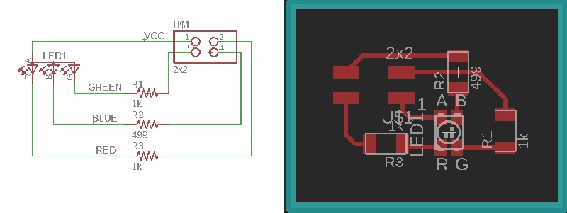
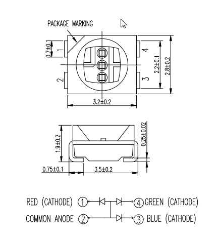
First I selected the wrong RGB LED, which looked very much similar, but board image had wrong connectors. To know how to connect the RGB LED, I took a look at the datasheet.
For the coding part, I used arduino IDE. So needed to check those pin configurations again.
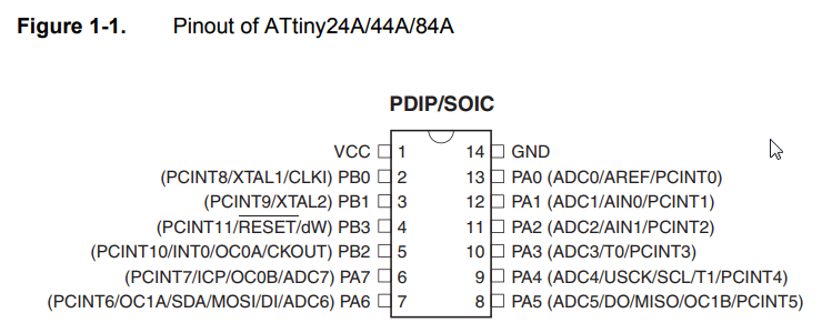
Comparing to arduino.
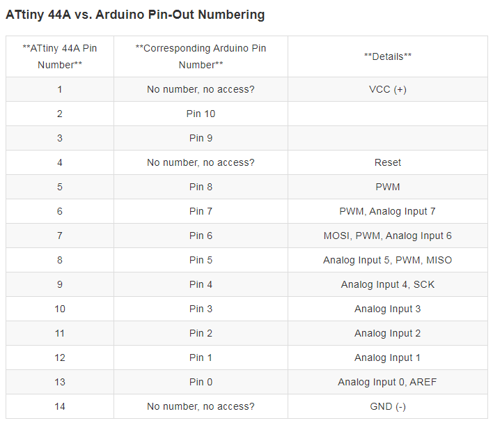
Define the pins.
const int LedPin2 = 7;
const int LedPin3 = 2;
Make it output
pinMode(LedPin2, OUTPUT);
pinMode(LedPin3, OUTPUT);
And lit it up or shut it down with HIGH/LOW.
digitalWrite(LedPin2, HIGH);
digitalWrite(LedPin3, LOW);
For showing purposes, I lit one led, added delay, and then lit another while shutting previous down. Code can be found in the end.
Here is a video of RGB board attached to Attiny44 board and lighting up RGB's leds.
I wanted to make a general purpose board with Atmega328P microcontroller, with couple LEDs on it. First one failed for some reason, no shorts whatsoever. I measured all connections and everything was fine. Still couldn't burn bootloader. So I made a 2nd one. This one worked, with some design flaws(1 airwire, wrong RGB LED part in design). I made corrections to the design files and added them to the end. For inputing and outputing I used the 2nd board. Design files can be found at the end.
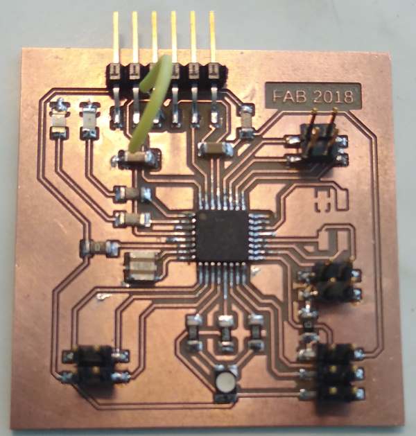
To program my board, I needed to know the pins to be used with Arduino IDE, with board set up as Arduino Uno.
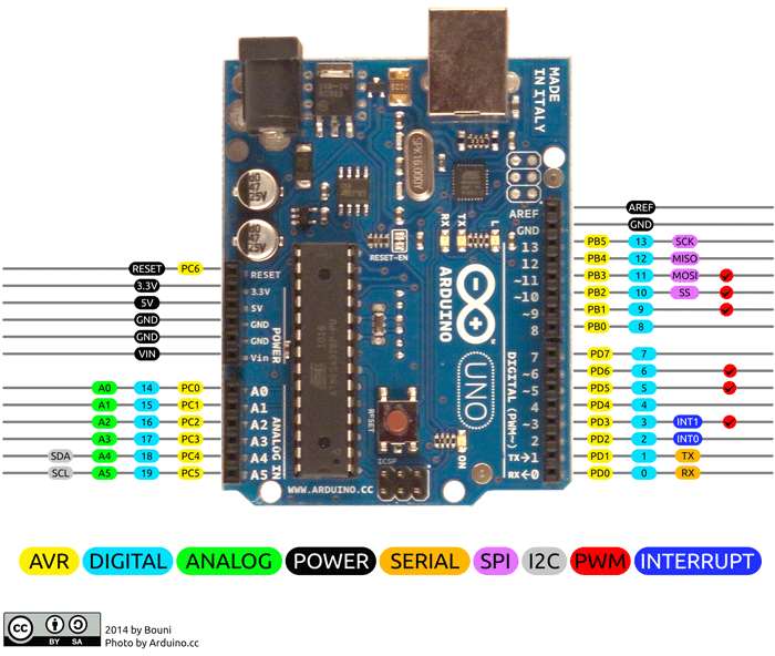
From Atmega328P Datasheet I grabbed microcontroller pin layout. Comparing this to previous image I can now program my input/output pins in Arduino IDE.
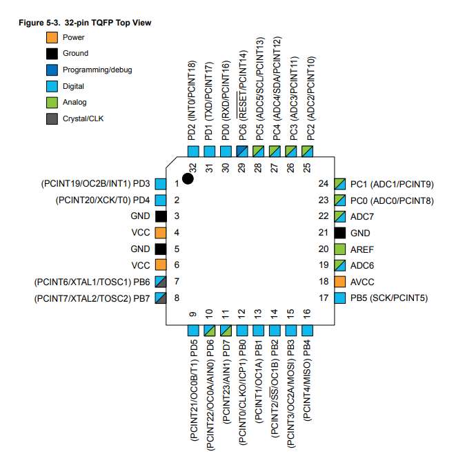
For programming, input needed to be analog. Checking out the tables above, pin 28(PC5) matches pin 19 in arduino. Setting that as INPUT, and onboard leds as OUTPUT. Reading sensor value in the loop, and litting up RGB LED based on the value. Code can be found at the end.
Here is a video for RGB board and light sensor boards attached to Atmega328P board. When light amount is low, its green. Blue led is on the middle and red lights up when in bright.
Group project
Group efforts can be found here.
Files
ATtiny44 codeRGB BOARD
Eagle schematics
Eagle board design
traces image
outline image
traces milling file
outline milling file
ATMEGA328P BOARD
Eagle schematics
Eagle board design
Trace image
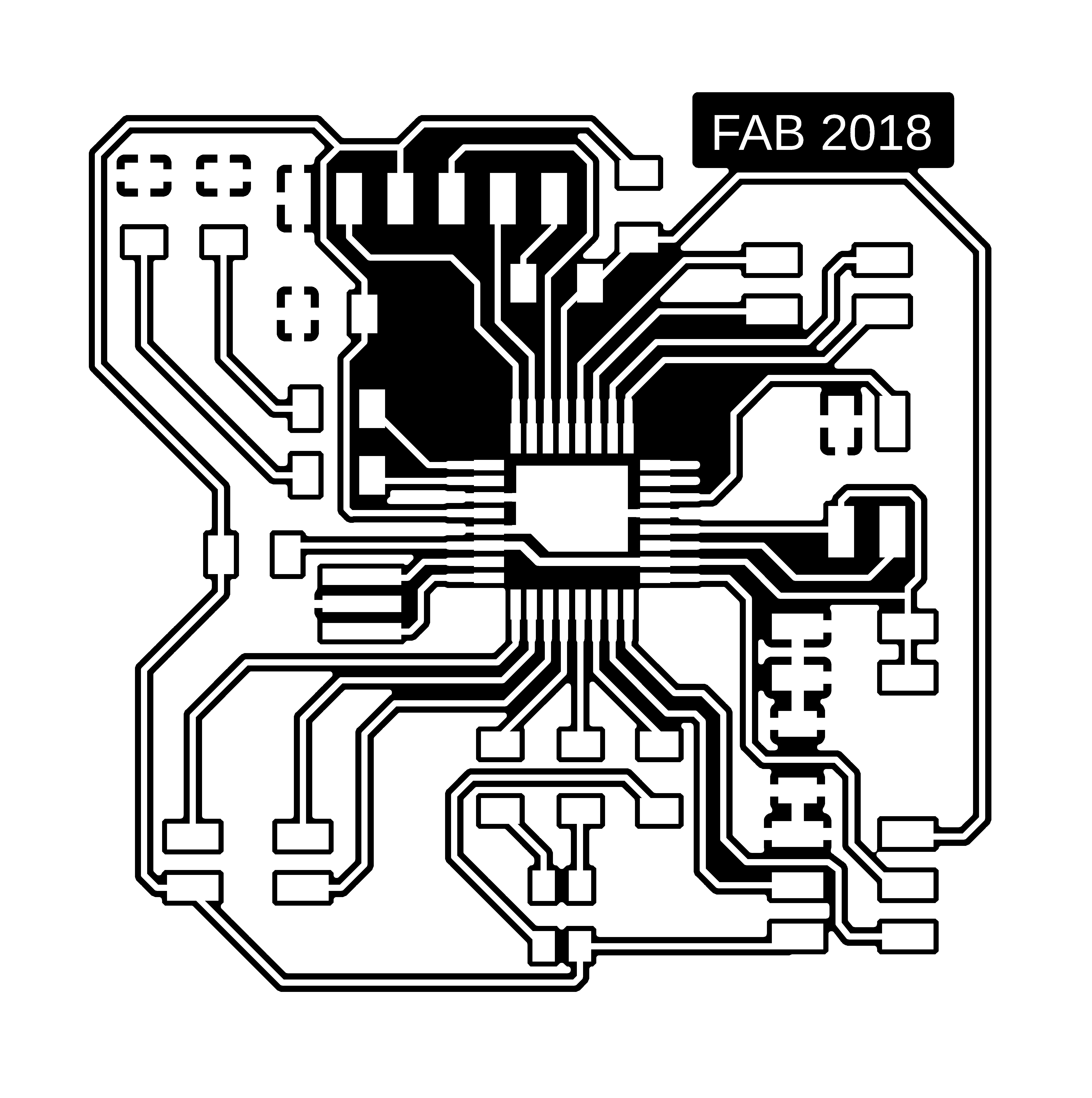
Outline image
Trace milling file
Outline milling file
code for atmega board