Using the vinyl cutter
The vinylcutter task was quite a straightforward one, and one that I had been waiting to try. I am so going to print out many many supercheesy wall decal texts (even though my kitchen is not seasoned with love), and I am going to try my hand at t-shirt pressing as well. But for now, I decided to try and find a picture that I would want to decorate my laptop cover with. And did I find one.... It is a sugarskull Stormtrooper motif i found online. Now unfortunately I do not know by whom originally, but I found tees featuring this decal atleast from Think geek, Design by Humans and Etsy. 
1. I first saved the picture in a .jpg form into my computer and opened it using InkScape. Then I selected the picture and used the "path --> Trace bitmap" tool.
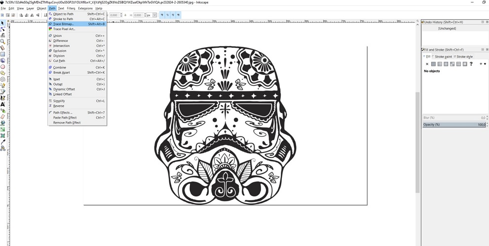
When you do the trace, it looks like nothing has changed, but there is actually now a picture on top of the original picture. You can see it when you move the trace
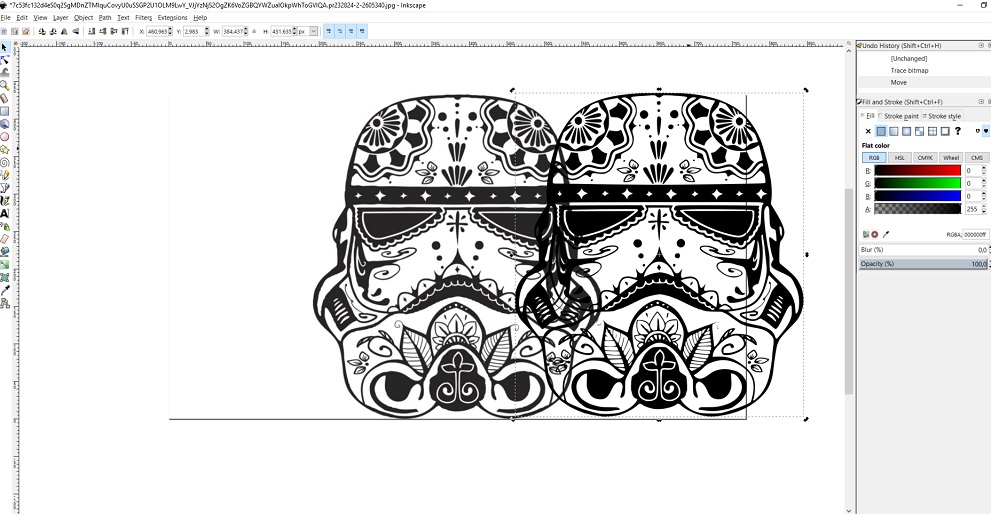
2. I then proceeded to delete the original picture from underneath the trace, as it is no longer needed.
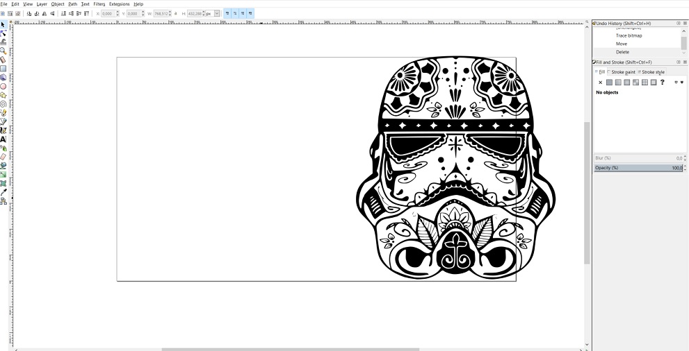
3. Next, I pressed the tool edit paths by nodes...
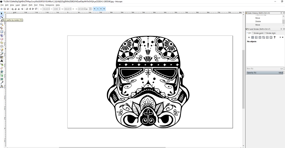
And clicked inside the picture
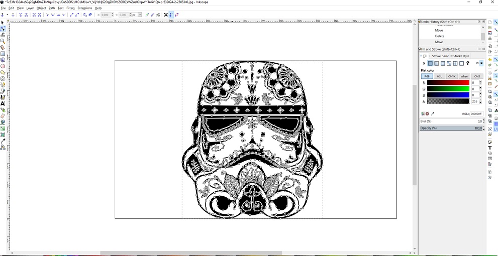
4. Next I selected to have the fill as "none" from the menu on the right
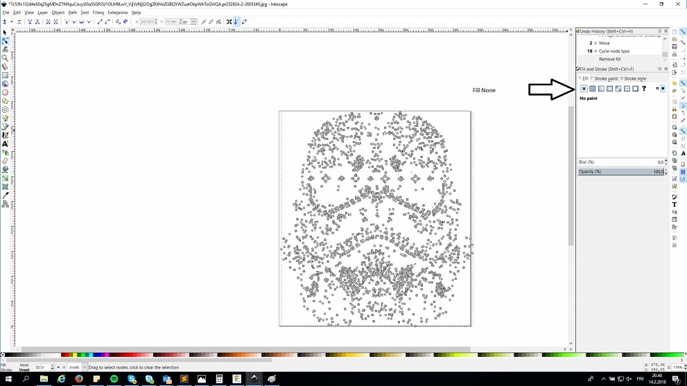
5. Then I set the stroke paint to flat colour
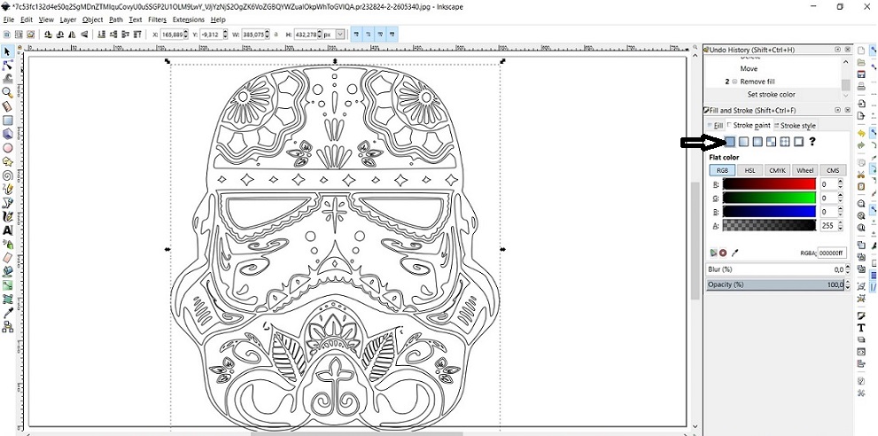
6. The last thing I did was saving the stormtrooper into a pdf file, to get it ready for printing
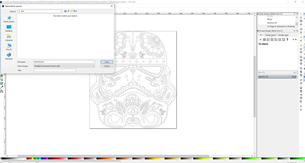
Then it was time to save the pdf file onto a USB stick and move to work on the computer that controls the vinyl cutter.The vinyl cutter at Fab Lab Oulu is a Roland GS24.
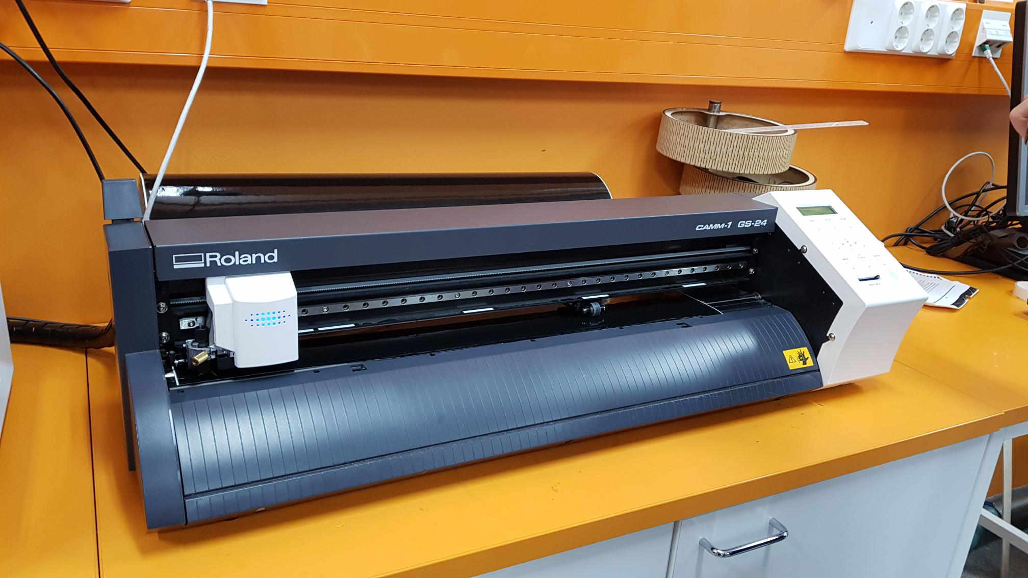
I raised the lever on the left hand side of the machine, and placed the roll of black vinyl behind it.
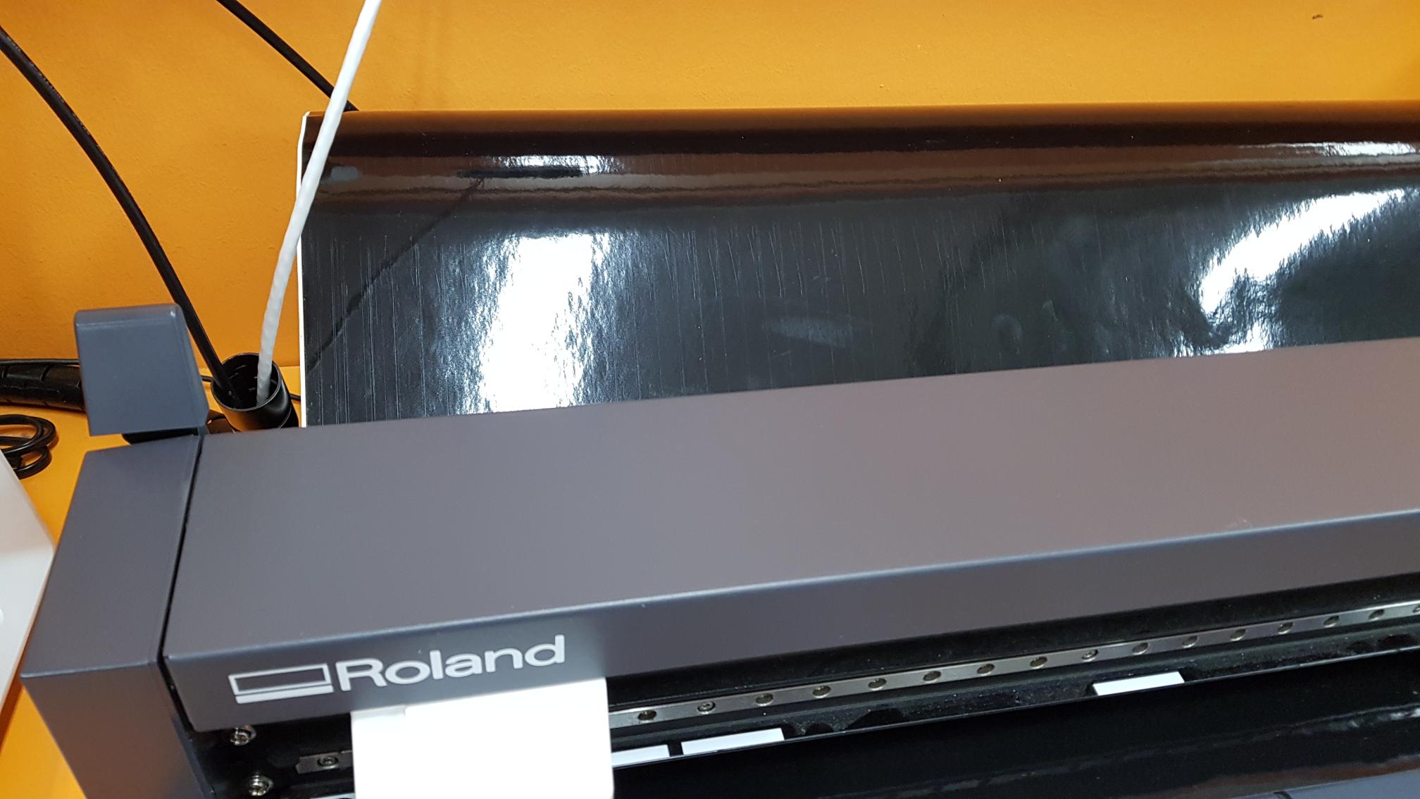
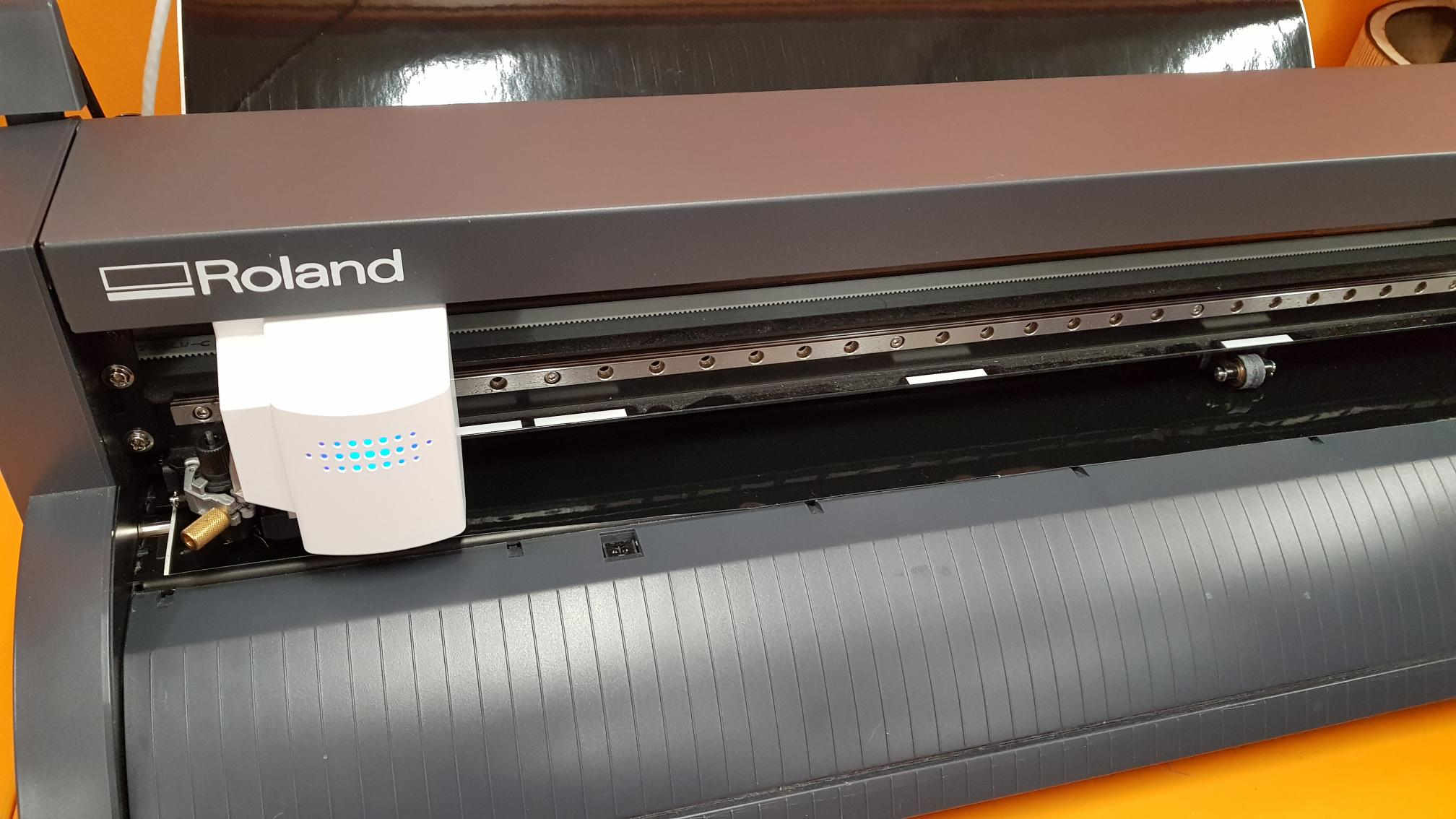
The vinyl was then pulled through to be under the cutter, and the lever lowered back down to secure it
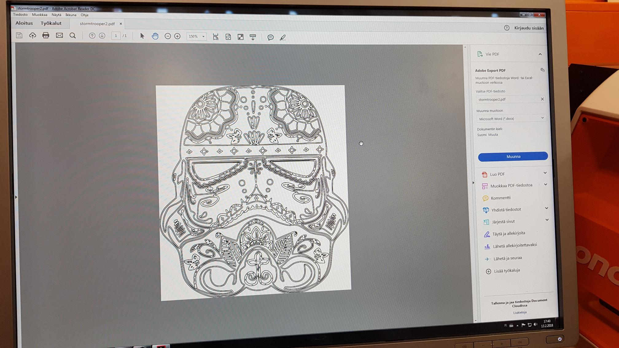
Next I opened up my stormtrooper pdf file in the computer that controls the vinyl cutter
I pressed print, and checked how big the print will be from the printer properties
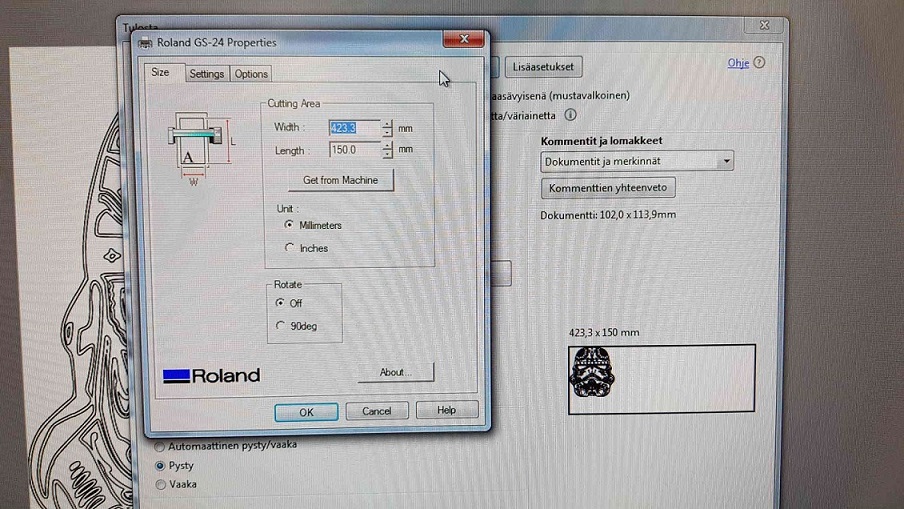
Everything looked fine, so I sent the file to the vinyl cutter by pressing print again
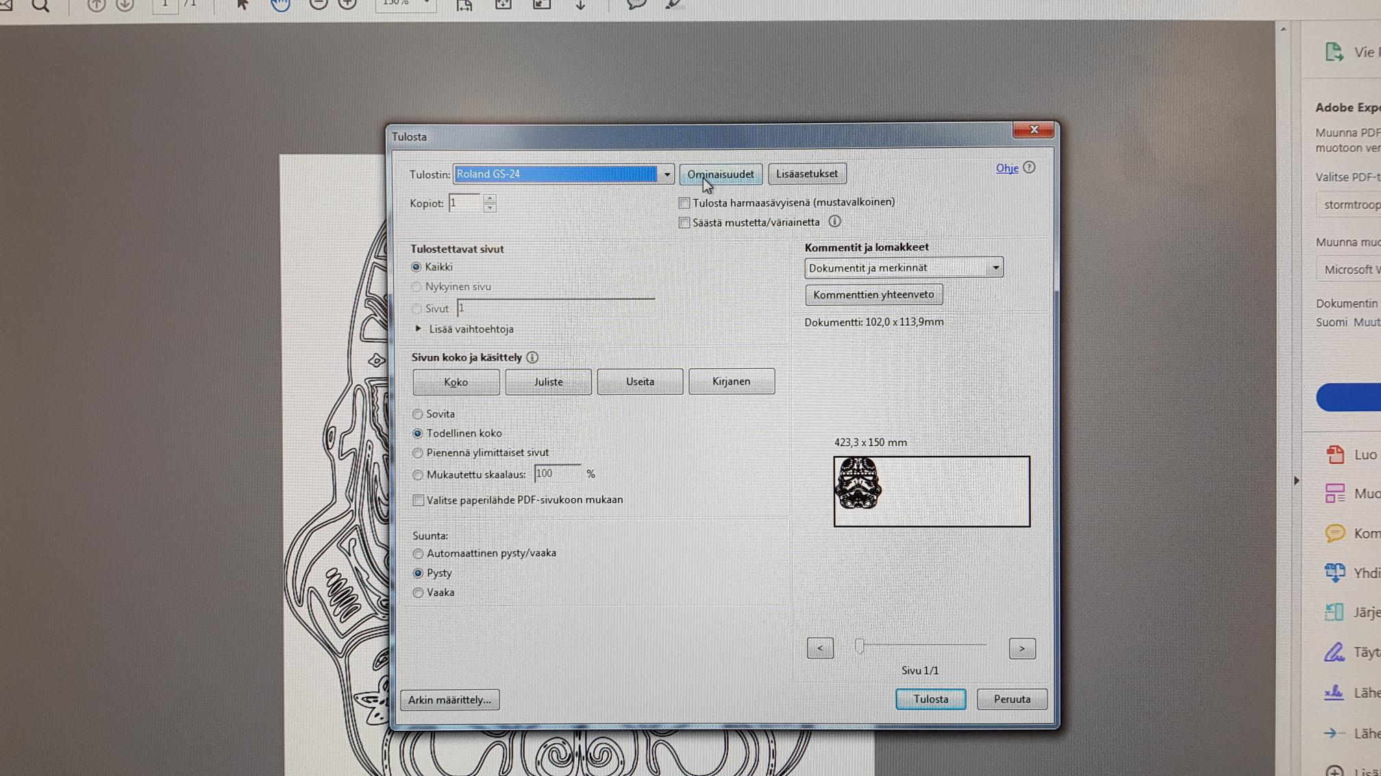
All i needed to do now was to press the corresponding print button in the vinyl cutter, shown here in blue
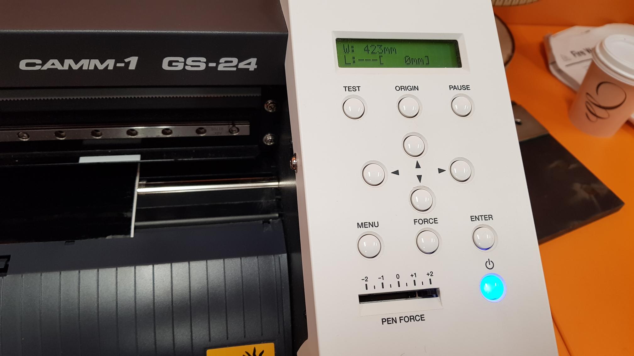
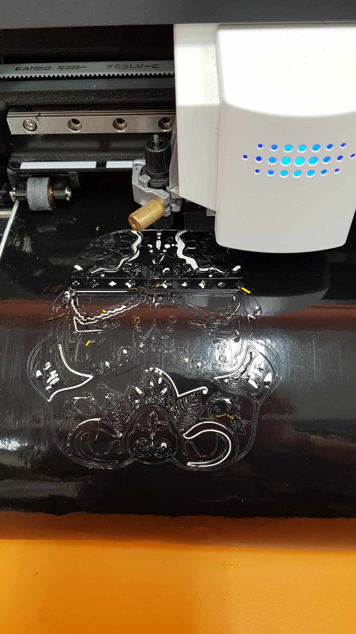
Here are some pictures from the cutting phase. At first everything looked fine.
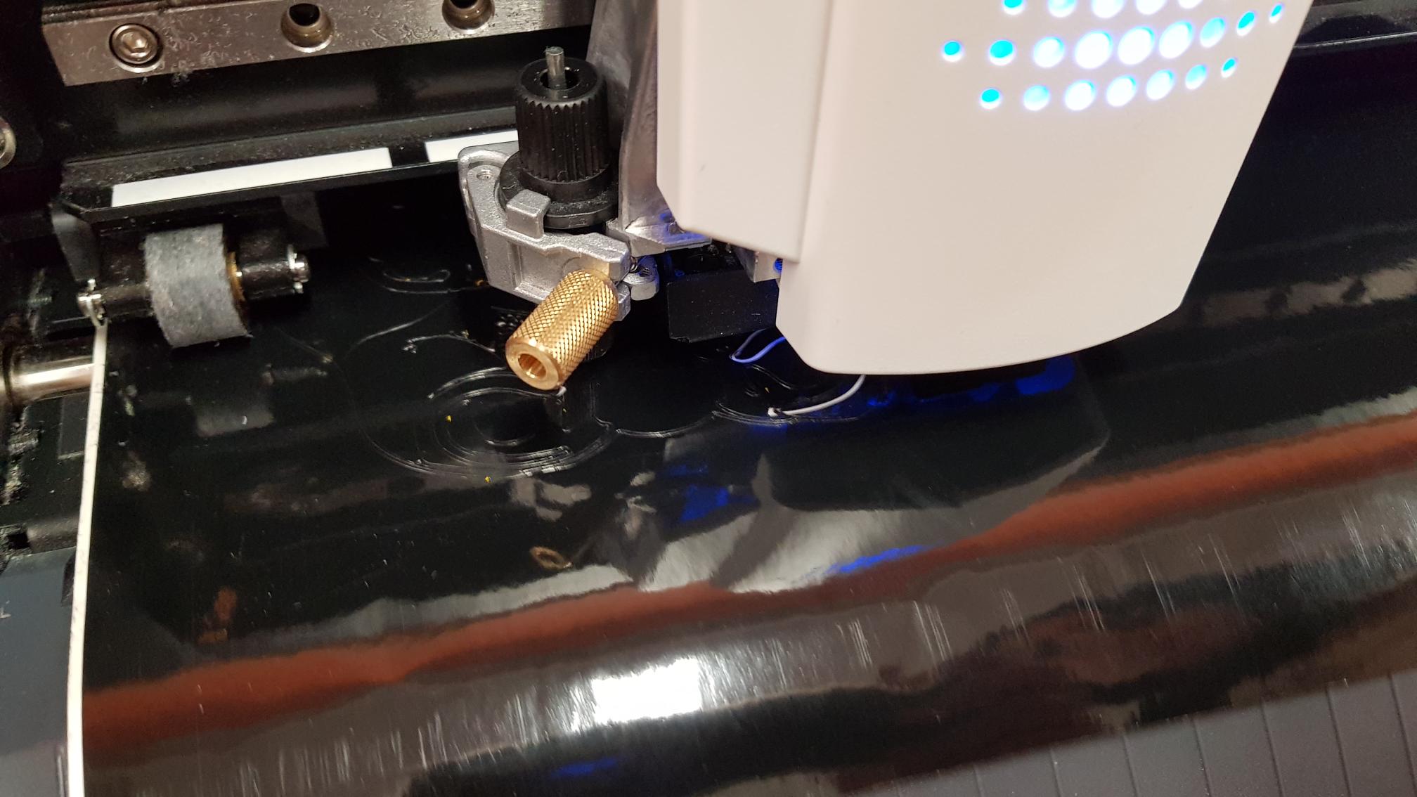
Then I noticed the cutter was leaving some yellow residue behind, presumably stuck to the cutter from the previous cutting job.
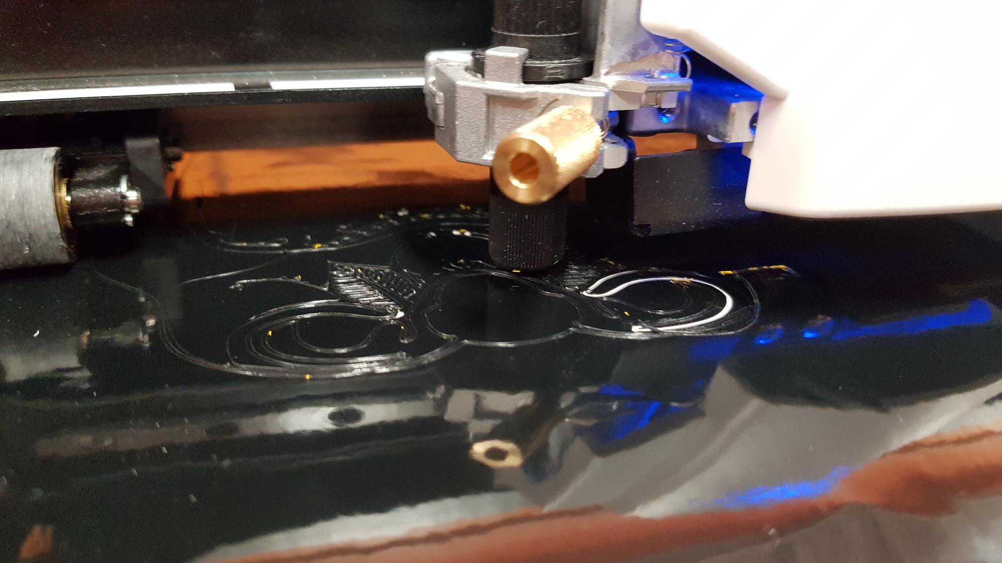
Then it all started to go wrong. The picture was too small and detailed for the cutter, the cuts too close to each other so the cutter pulled details out while working
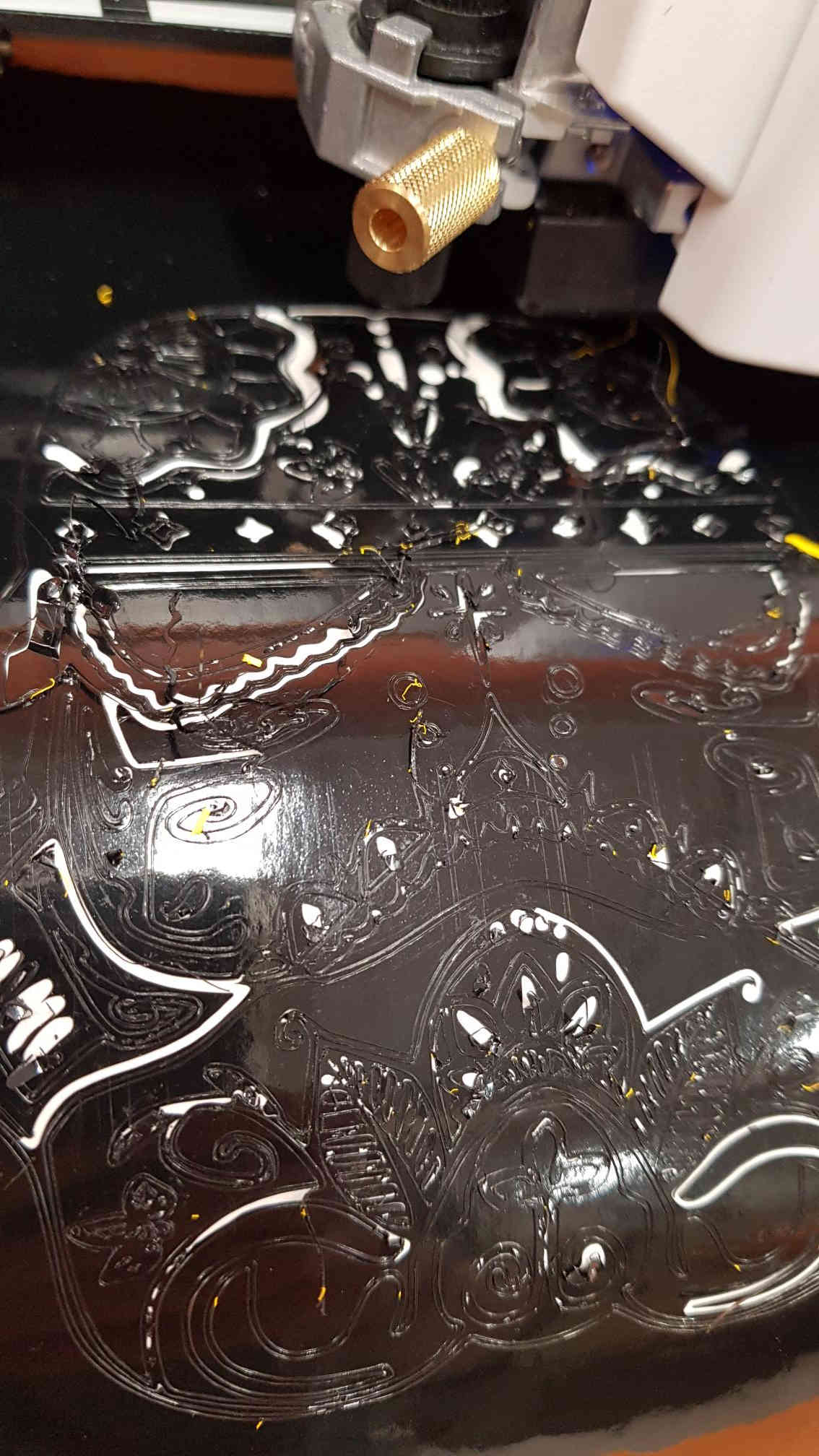
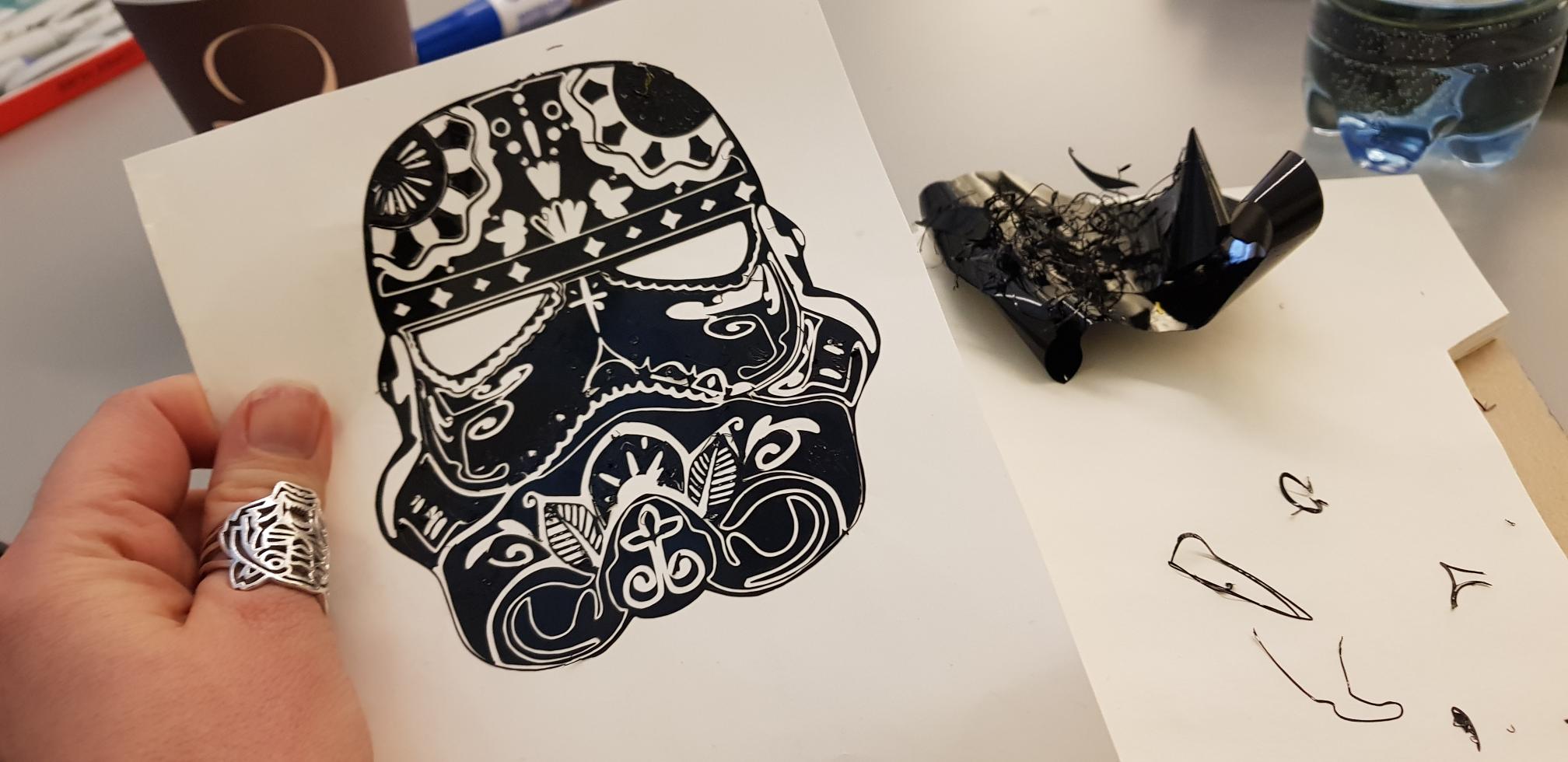
The finished sticker is not too bad. But not too good either. I spent a long time trying to remove the parts that didn't need to be there, and also ripped out a lot of parts that I would have wanted to keep. Apparently though my Stormtrooper would have been succesful had I printed it a bit larger.
Files
- The original stormtrooper image
- Stormtrooper svg file
- Stormtrooper pdf file
------------------------------------------------
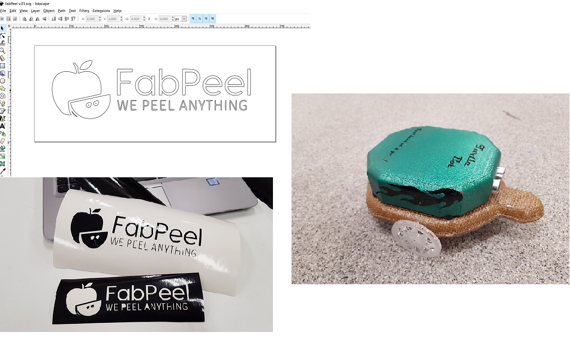
Edit 20.6: have also used the vinylcutter later on in the FabAcademy. On the Machine design and mechanical design weeks I prepared and cut the logos for our groupwork using inkscape and the vinylcutter, and during the last phases of my Final projectI prepared stickers to decorate my turtle robot.
Designing the press-fit construction kit
A press fit is s a fastening between two parts which is achieved by friction after the parts are pushed together, rather than by any other means of fastening. Like Legos! To try and find inspiration for my own press-fit construction kit, I browsed around in the FabAcademy archive and turned to google. I browsed around for about a hour, and found a lot of nice designs that I liked: For example The grasshopper, this Dollhouse kit, and this flower motif. They were all really pretty, but I decided to try and parametrically design and print the press-fit kit that our groupmember Jari had introduced in the groupwork - A simple square design with slots on each side that can be fitted to create all sorts of shapes.
As Jari had done the parametric work for the first version with FreeCad and showed the rest of the group members the basics, it was time for me to start from the scratch and try and put my own spin on things.
First I created a rectangle....
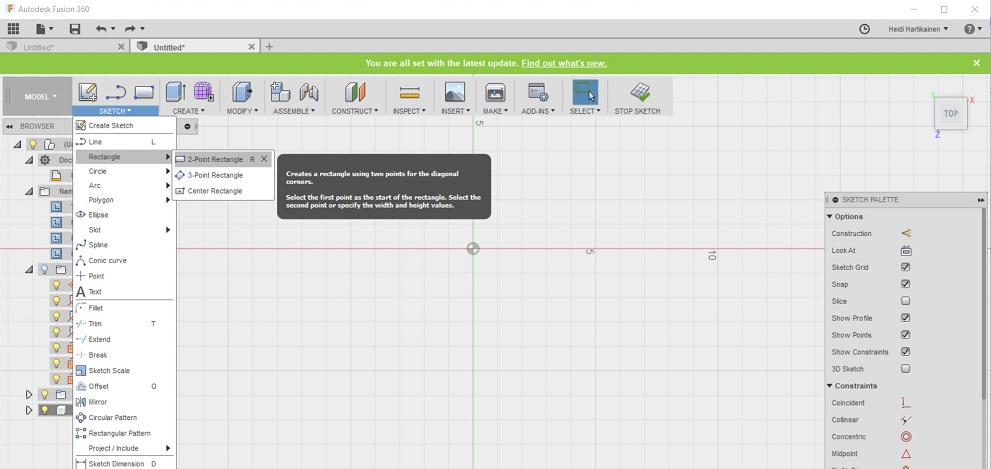
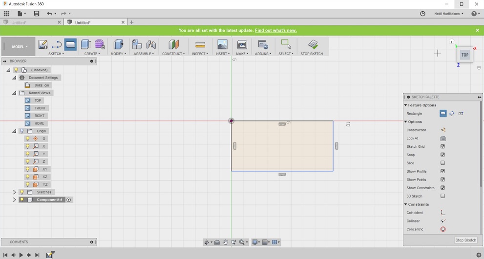
... and placed it on the sketch
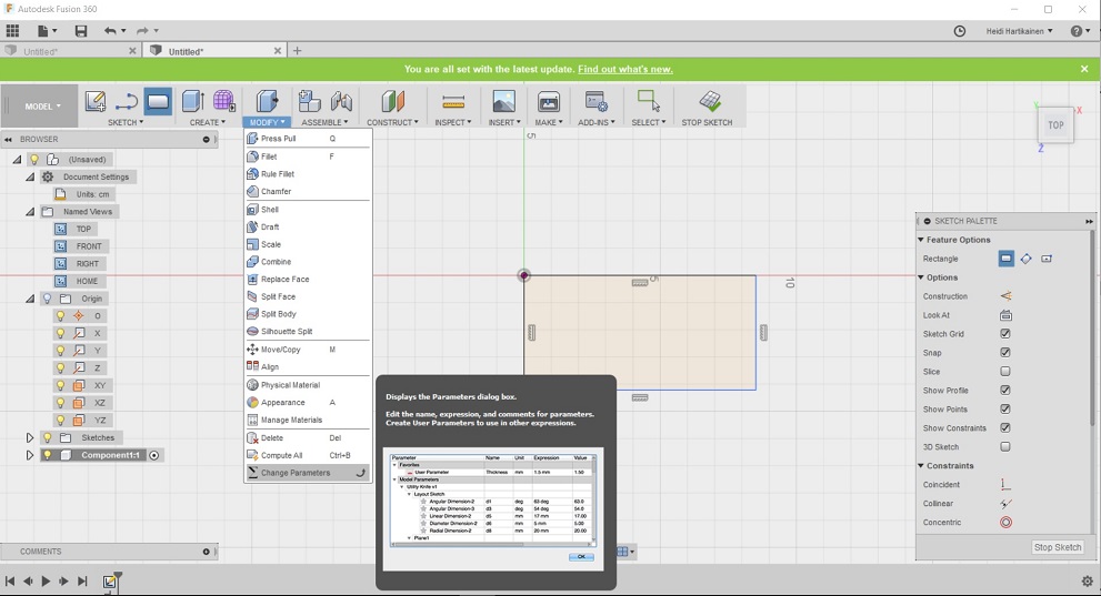
Then I selected modify, change parameters
And started to input the parameters for my design
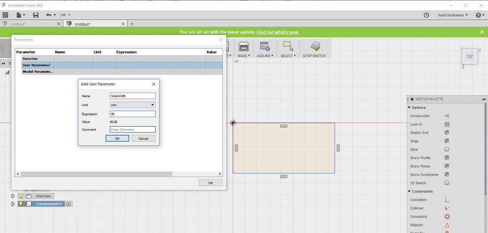
- I specified that I wanted to have each side as 40mm.
- I also wanted to add a gap to each side of the rectangle, and I originally specified the depth of this gap to be 9mm and width for this gap to be 3mm
- I was told by our local instructors that I should take into account the kerf that we measured (0.08) in the depth and width of the gap, therefore I also added this parameter, and changed the gap depth to depth - kerf *2 (8.84) and width to width to width - kerf/2.
- I also specified that I will be using a plexiglass or mdf board that is 3mm thick (Note that I have erroneusly marked vinyl in the picture, which is however an absolute no-no with the laser cutter as it emits chlorine gas as it is cut .
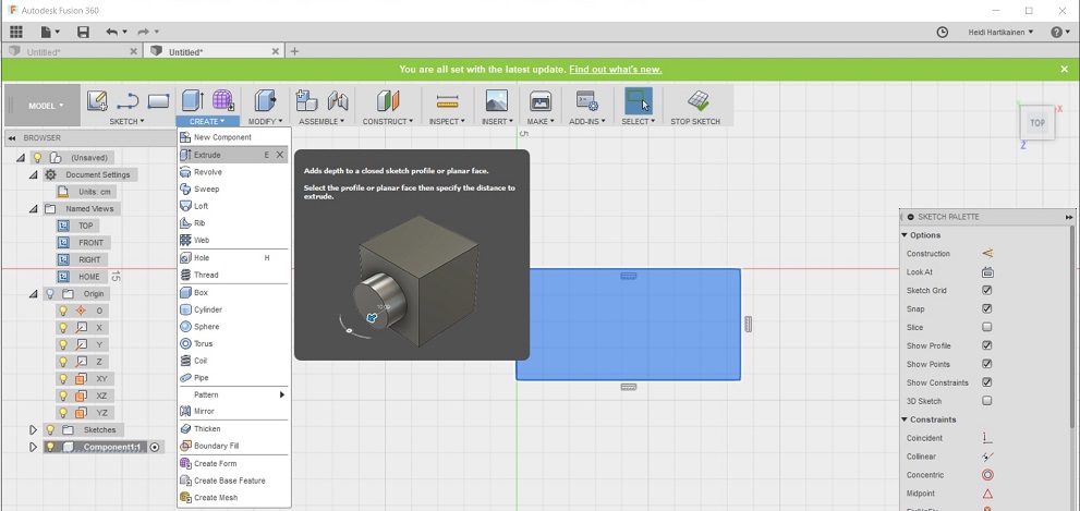
Then I started to incorporate these parameters into my design. I selected create --> Extrude
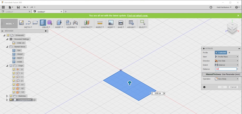
and then raised the surface the amount specified in parameter "Material Thickness" --> 3mm
Next I specified that I want the different sides of the rectangle to be as long as specified in parameter "RectangleSidesWidth" -->40mm
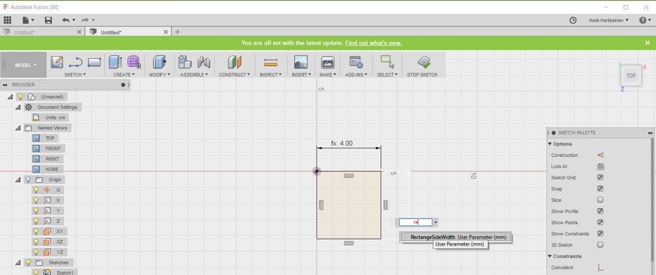
Next I drew a rectangle on one side of my triangle, and specified it's width using the parameter "GapWidth" -->2.92mm
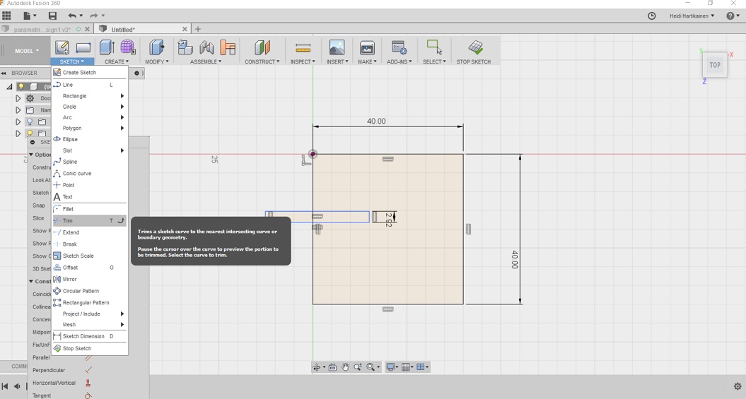
I used the trim tool to remove the "extra lines" from the rectangle
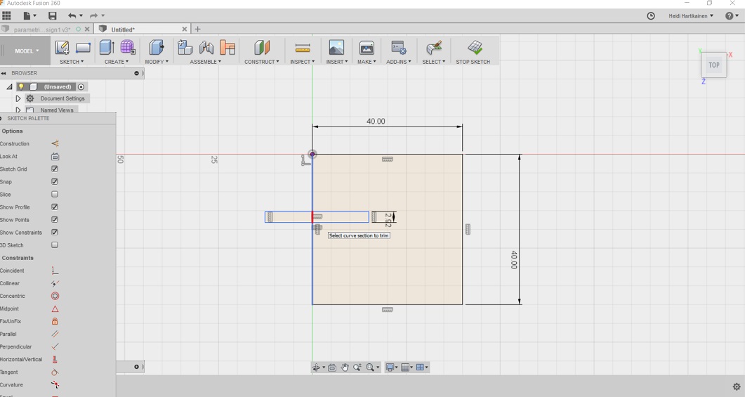
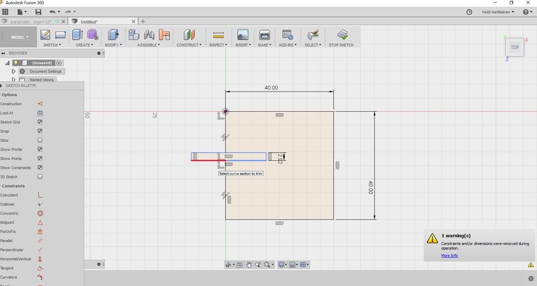
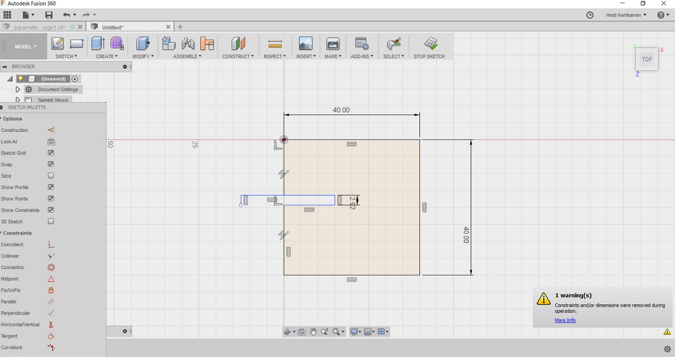
And then specified the gap deepness using parameter "GapDepth" --> 8.84
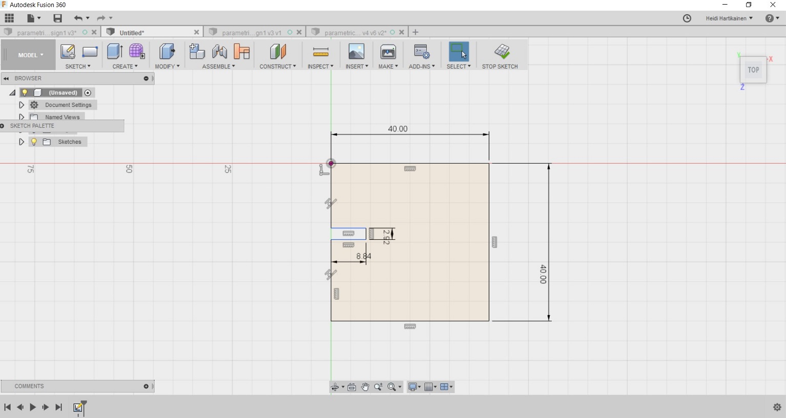
I repeated the process on each side of the rectangle, making sure that the gap was on the middle of each side (It can be moved during the process). Then I had the gaps on each side.
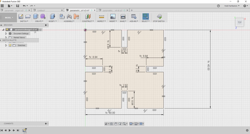
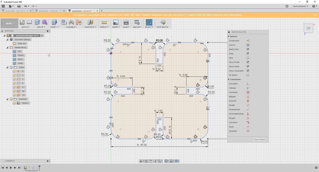
Then I used the "fillet" -tool to round all the sharp edges.
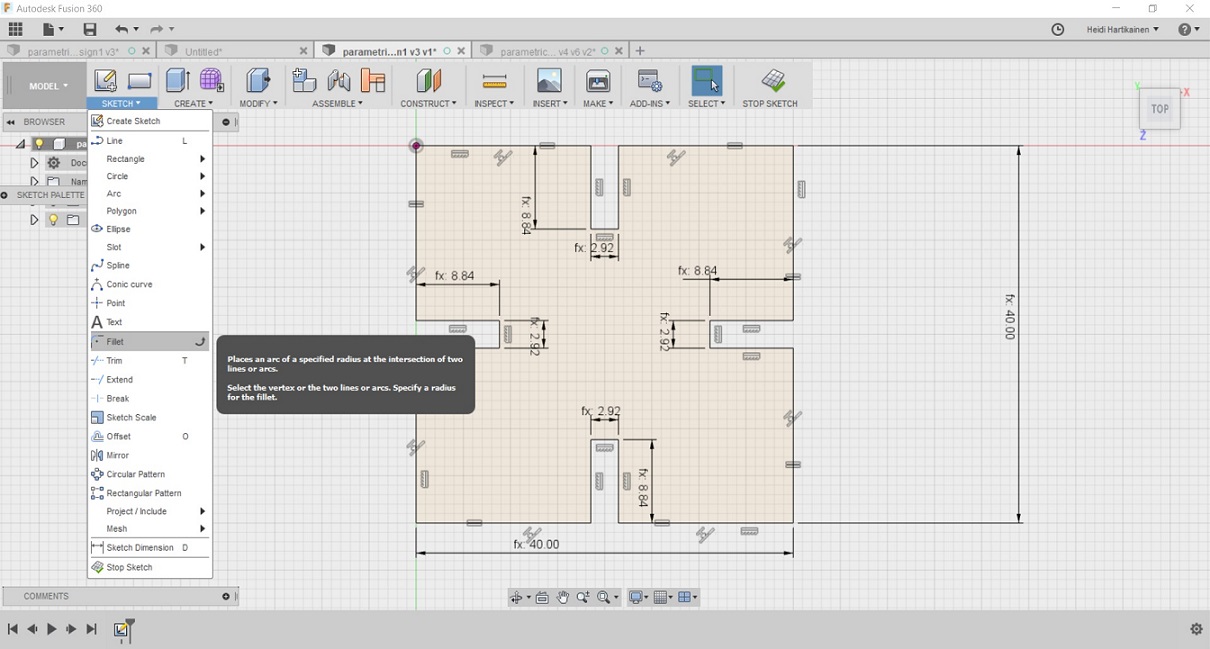
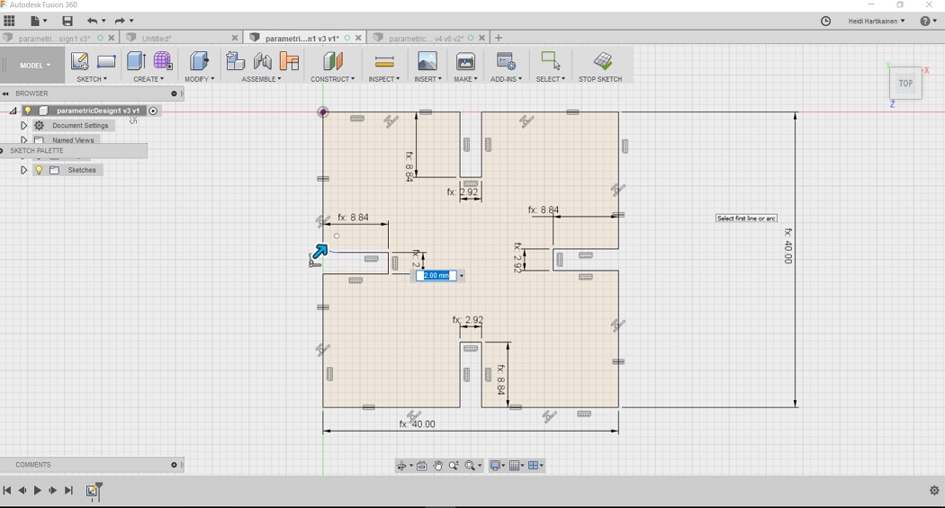
Here is the finished parametric design.
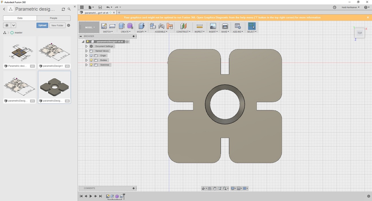
Before production, i still fancied it up a bit by adding a hole in the middle, by using the create --> hole tool. The hole has no function. I just wanted the design to resemble a flower, so the hole represents it's center.
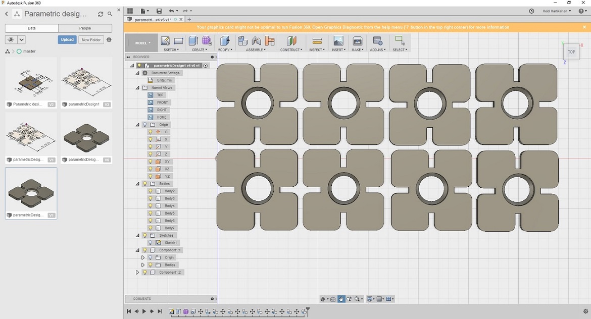
For printing I copied the design, and added 7 more close to each other
To save the file, I clicked drawing --> From design
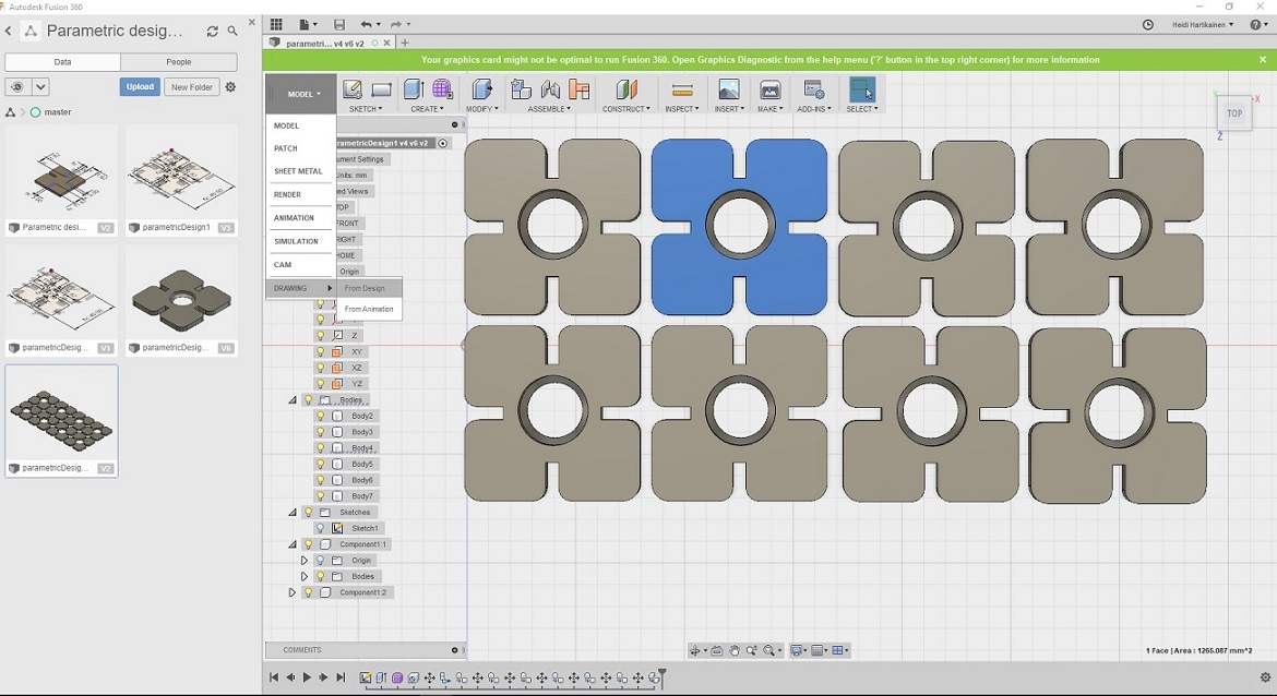
Selected the output to be pdf, and proceeded to save my design
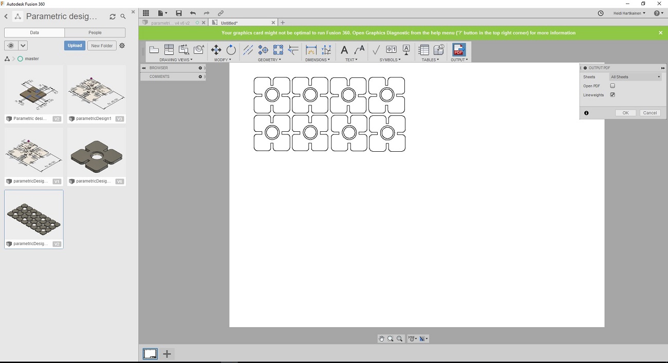
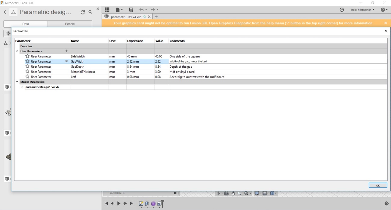
Note: I was later instructed in our local evaluation that I had understood parametric design wrong: "You used table and variabled but this design is not parametric. If your gap widht would be for example expressed “material_thickness - kerf”, then you could simply change material thickness or adjust kerf and the design would still work." --> Because of this, I modified my original design file, and corrected the issues later.
Here is a screencap of the revised parameters. The corrected file is also attached below.

Files
- Original design as .pdf file
- Original design as .f3d file
- Revised design as .f3d file
Using the laser cutter
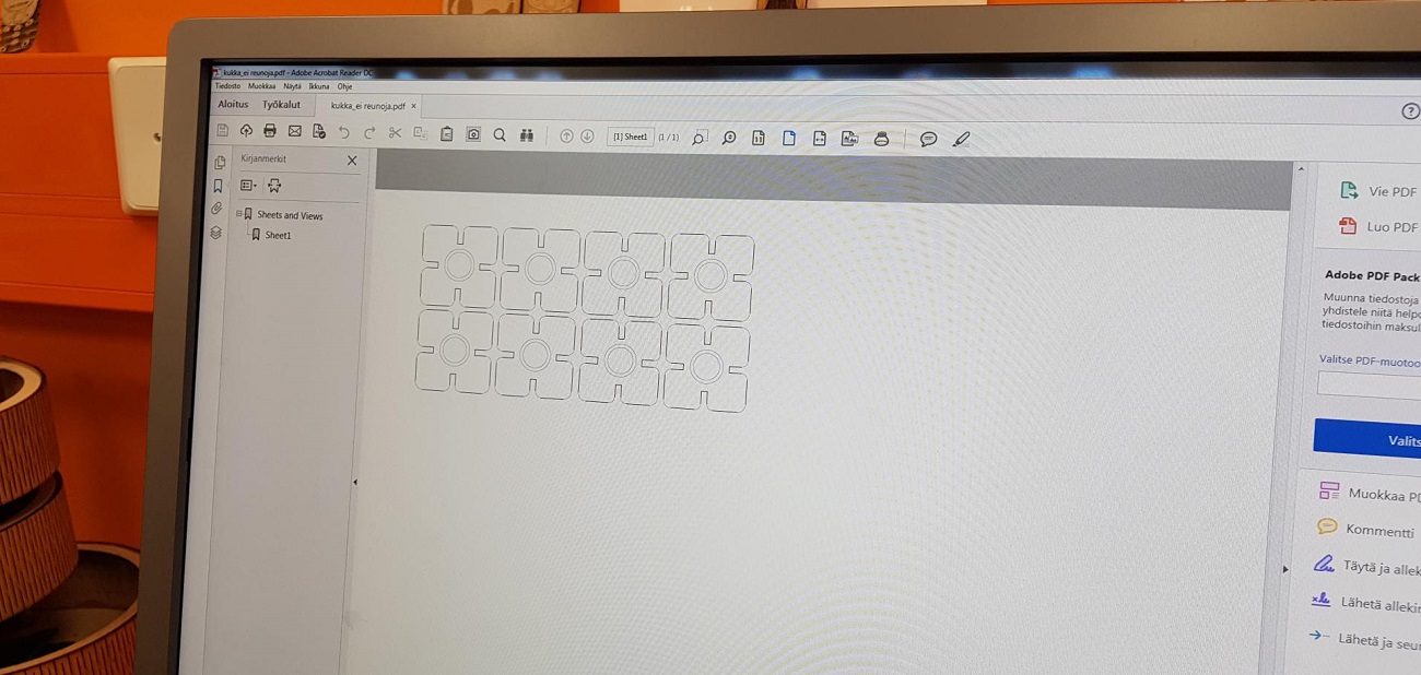
I took my pdf file and moved to the computer from which we control the laser cutter. I opened my file and pressed print.
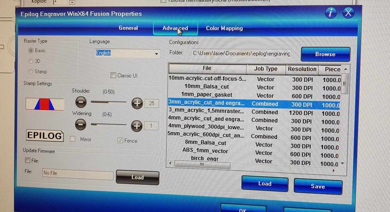
The control panel for the laser cutter opened up. In the "General" -tab there are already some predefined settings. But there is an option to change values such as speed and power. I did not change any settings here as this was my first time using the machine and I wanted to test the default settings out. So the job type was set to vector, and vector settings were speed 8%, power 100% and freq 100.
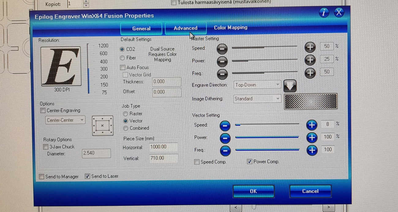
In the "advanced tab" I could choose the material I would be using to print. I selected 3mm acrylic
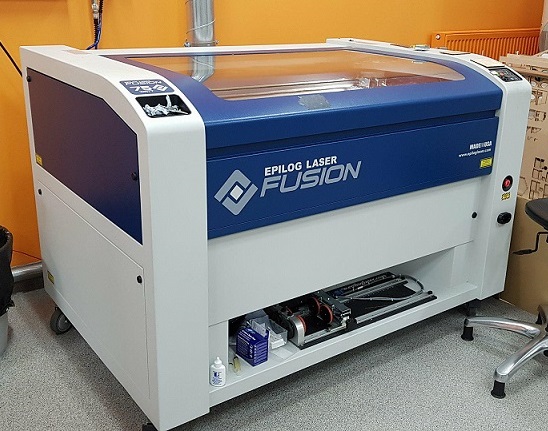
This is the laser cutter in FabLab Oulu, which was used to cut the design
Once the file had been sent for cutting, and the material had been inserted into the machine, you need to check that the ventilation and the air pressure are on.
After that, the starting point for the cutting is set with this "joystick"
.
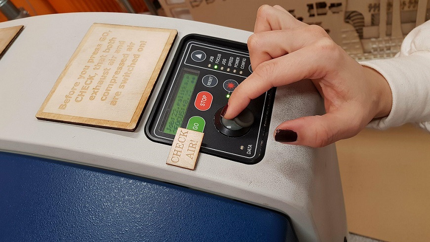
- First, set the focus: Select focus in the menu and move the tray up and down until the laser is at a correct distance from the laser head. The correct distance is measured by hanging a small metallic tringle from the laser. You move the tray up, until the material touches the triangle, then remove the triangle - Finally press the joystick to set the focus.
- Next, set the Origo. This determines where the machine will start to cut. It should be the top left corner of the file. Select Jog in the menu and move the laser with the joystick; press the joystick when ready.
- After the focus and origo are set, the cutting is started by selecting the file from the "Job" list and pressing "Go".
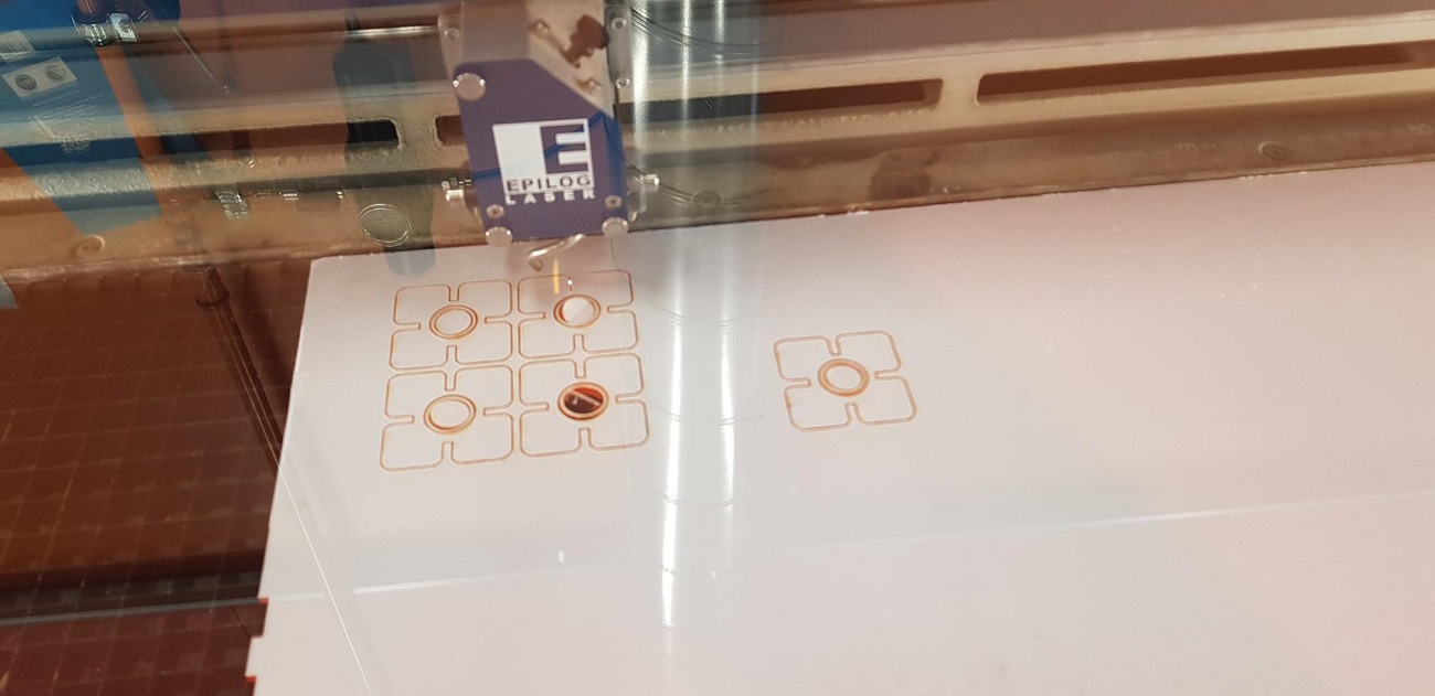
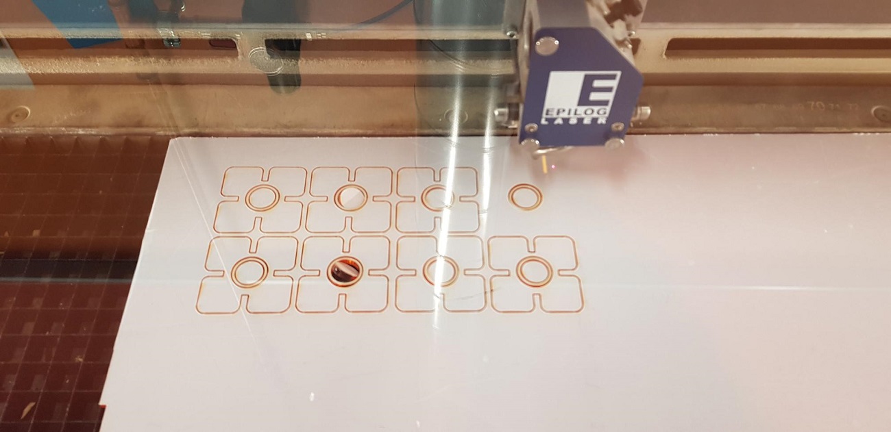
Here are some pictures from the cutting phase
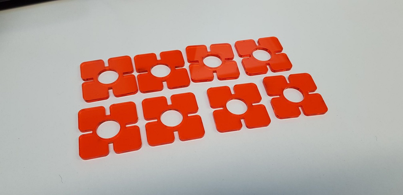
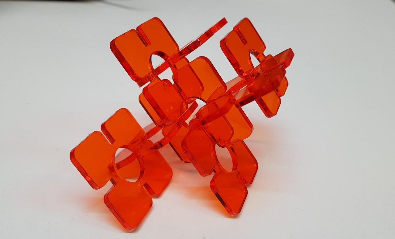
And here are the finished pieces to my press-fit kit, with the white plastic film removed.
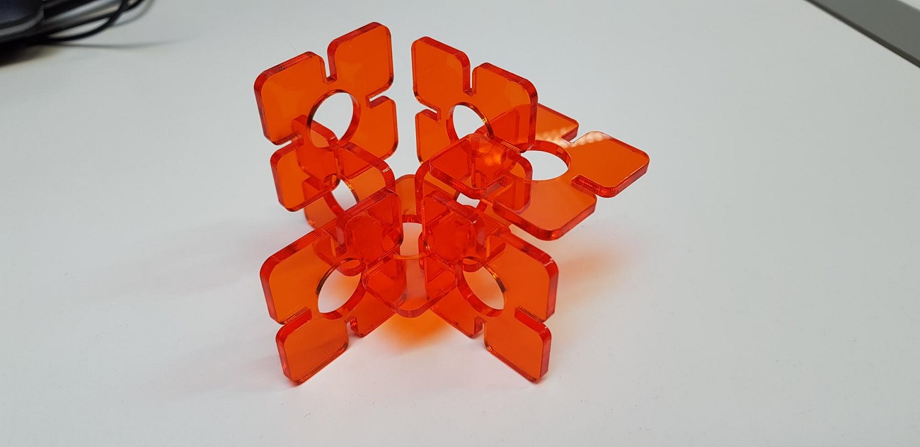
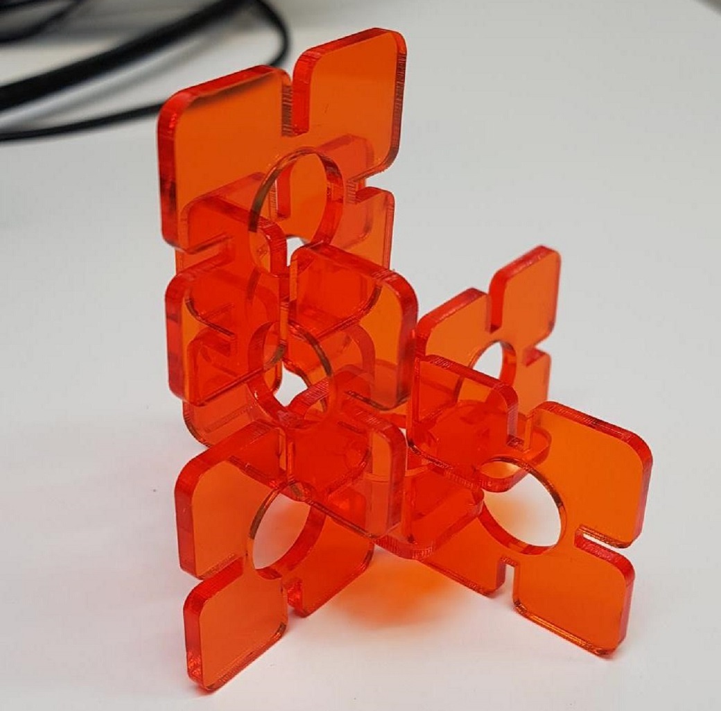
I think they turned out great! The fit was tight, but not too tight. The pieces fit together nicely without any wobble or fear that they would fall off.
Problems had, lessons learned, questions that remain
- My vinyl cutting didn't turn out great, and I noticed you can not do too detailed work there.
- I tried to do the parametric design in my office on my own for a day, and didn't manage to make much progress. I noticed that when working in the lab where there are others it is much easier. Learning from mentors and peers. Instead of scrolling through help sections and internet discussion boards for solutions I could just ask, which was much faster. Help was always close.
- Turns out, I had still gotten parametric design wrong, doh! I corrected the mistake/design later on however.
Copyright © Heidi Hartikainen 2018
Template copyright ©Blackrock Digital LLC 2013-2018

This work is licensed under a Creative Commons Attribution-NonCommercial-ShareAlike 4.0 International License.