MACHINE DESING: FAB KATARI
The assignment of the second machine building week:
Actuate and automate your machine
Document the group project and your individual contribution.
Machine Design: Fab Katari
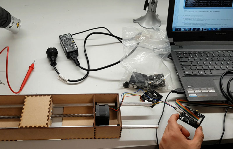
Testing the mechanism using a gestalt node driving a stepper motor
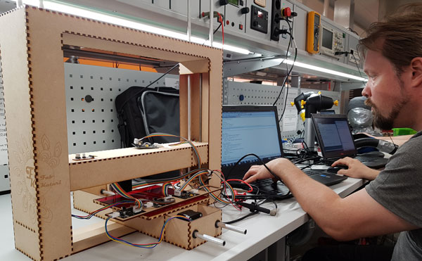
We continued machine designing by running a test code for moving the motors on the axes. For that, Jari downloaded a test code for driving motors using gestalt nodes. After some thinking, we managed to get the first motor running!
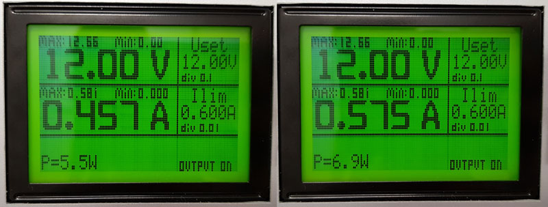
The machine consumed less power while it was moving compared to standing still, because we didn't disable the motors, while they were not moving and it consumed full power to hold its position while not moving. This can be fixed with using disable motors in the code.
However, when we wanted to test if the other four boards work too, they didn't. After figuring out the error for a while, Jari found a reason of the issue. The issue was with the .vmp file, which needed to be deleted. It contains identification of each node. All the axes are identified by pressing button in the gestalt node. The code creates .vmp file based on that and the initialization has to be made only once, if the nodes remain the same and are used to control the same axis all the time.
3D Designing and Printing the sensor on the Z-axis
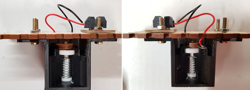
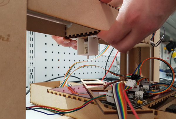
Ari started to work on the 3D designing of the sensor for the surface measurement with Autodesk Inventor 2018. Originally, Jani suggested for us that the sensor could be made with piezoelectric needle, but there was quite a little information on that. Luckily, Bas suggested that we can make a press button, which can be lowered on the surface and when the circuit is connected, we can read the position in all axes.
Details of the 3D designing and printing Ari's Documentation.
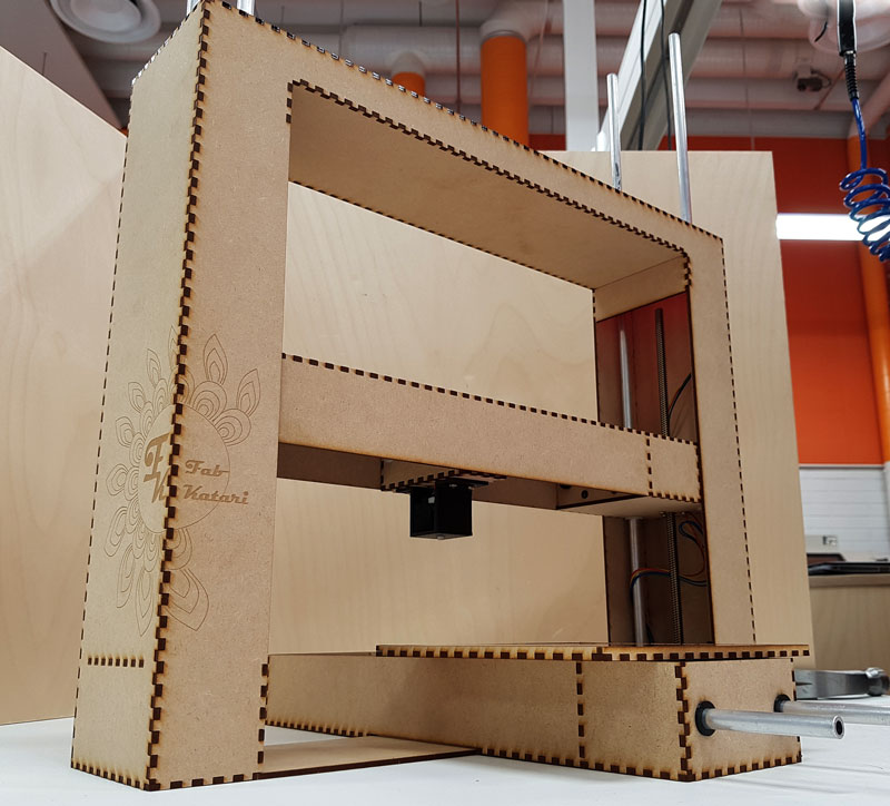
 Ari working on the button sensor
Here is the stl model of the button sensor on the head of the Z-axis:
Establishing connectivity between gestalt nodes and computer and programming
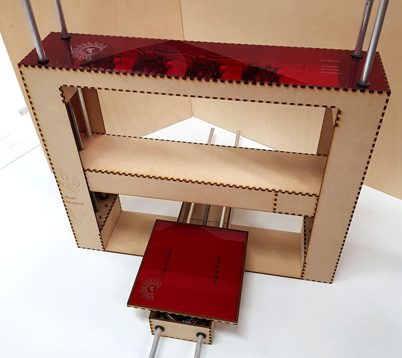
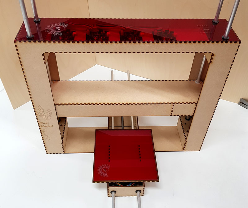
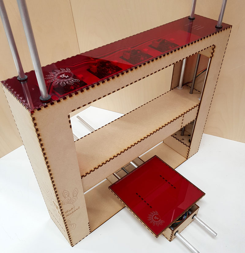
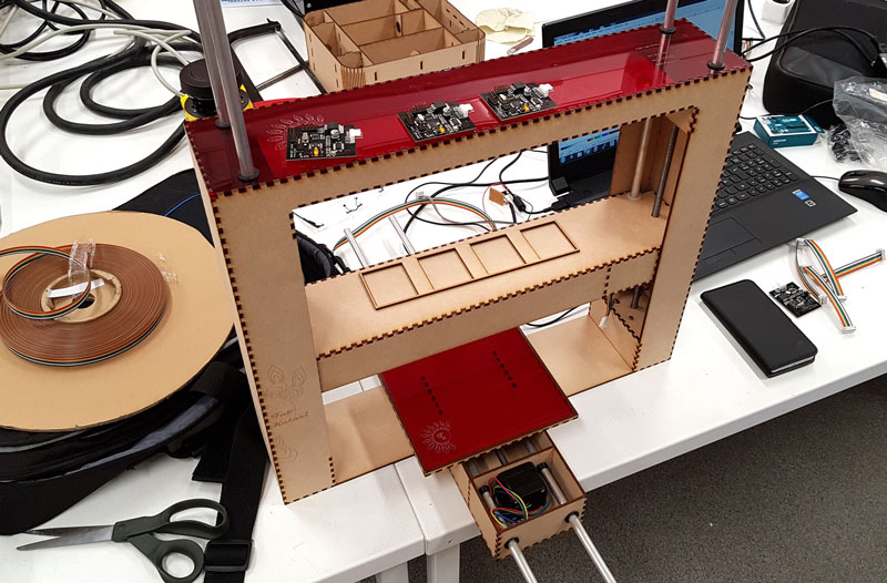
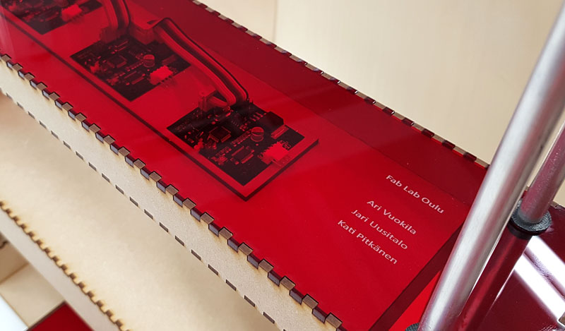
Jari designed a holder for the gestalt -boards to be located on the bridge of the machine, under the red acrylic sheet so, that the boards are standing there nicely in order and visible throught the top sheet.
For running the machine, we are using four NEMA-17 stepper motors, and one gestalt node board for each of them. Together these four nodes form a multi-drop network, sharing a single set of communication wires and are controlled through fabnet(RS-485 bus with few additional signals). Fab Academy tutorial was a nice help to get started with this.
We managed to make the basic mechanism of the machine working. Details of establishing connectivity between gestalt nodes and computer can be found from Jari's Documentation.
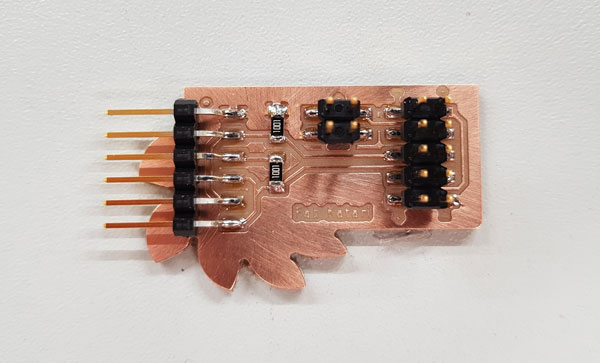
To establish connectivity between nodes and a computer, and providing proper power, requires: high and low voltage power supplies, an adaptor board (076-000A) with bias resistors, and FTDI -connector cable. We considered, that it would have been nice to attach the bridge board on side of the machine for easy access. To make this, we aimed at adding a small additional value for user by modifying the cable, and add VDC plug-in adapter on top of if for powering the machine easily. For this, Kati designed and created the bridge board prepared for adapter and also using fixed 1x6 pin header for FTDI.
However, we didn't go far enough to find, that it is not the original TTL-232R-5V FTDI-cable that we are going to use to use, insted we will need a USB-RS485 converter cable. This is why Kati changed the order of the FTDI-cable to fit it straight through to commercial cable, but right after found that it was unnecessary. Because we didn't have more USB-RS485 -cables in the Fab Lab, and we didn't manage to add a VDC adaptor on our new board, we decided to not break the working cable+board combination from the previous year group work but to continue using that one.
Details of considerations regarding the bridge -board can be found from Kati's Documentation.
Video
Future Development
As there is a lot of delay in reading the sensor, this could be troubleshooted more to see what is causing it. Other option is to switch using fabnet with additional node specified for reading and sending sensor data. Resolution could then be improved by switching the button sensor to piezo needle. Also nothing would stop using this 3-axis machine for example 3D printing or CNC milling by just changing sensor head to printing head or to milling bit. Moreover, at this point the modular Y-axis for changing the function of the machine is unfixed, and the attaching system of the axis should be developed.
Files
Here are the files of machine design:
- Here are the files of 3D Designing and Printing
- machine_switch.ino Code for the button
- check.py Python code to check the button state
- machine.py Python code for the machine operation