MECHANICAL DESING: FAB KATARI
The assignment of the first machine building week:
Design a machine that includes mechanism + actuation + automation
Build the mechanical parts and operate it manually
Document the group project and your individual contribution
MECHANICAL DESING
Starting to work
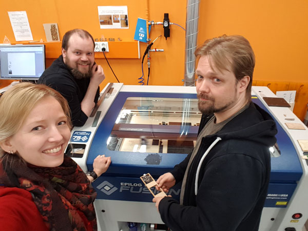
Our local instructor Eino Antikainen facilitated us on the Mechanical Design week to get started. Three of us found a shared interes in making some three-axes machine moving three dimensionally so, we formed a group. At first we had several ideas in the air, from painting machine to milling machine but finally, according to Eino's suggestion, we decided to build a surface measuring machine that can measure and check how even some surface, such as PCB board, is. This was because, on the input week we had several problems with bended boards and as a result of that failures in milling.
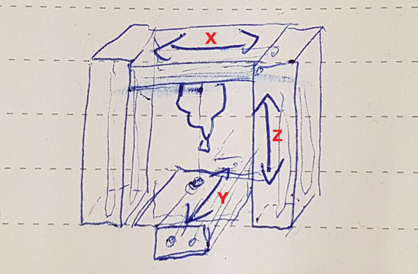
Ideating the mechanism and the structure of the Measuring Machine
We started from building a shared understanding of the machine and it functioning. For this quick prototyped machine we will build a solid measuring head located at z-axis. Kati started to work on the project documentation right from the beginning, took photos and documented the workflow, decisions made and both successes and failures during the working phases. More over, she nicknamed the machine Katari.
We had a couple of ideas for the axes mechanism, how the axes could be located and move the head. One idea was that X- and Y-axes could be located to the bottom part over the plate that the machine is going to measure and then Z-axis would have been in on of the ends moving the measuring head up and down. However, we considered that this type of mechanism requires at least very steady legs and propably also some weight to counterbalance the axis.
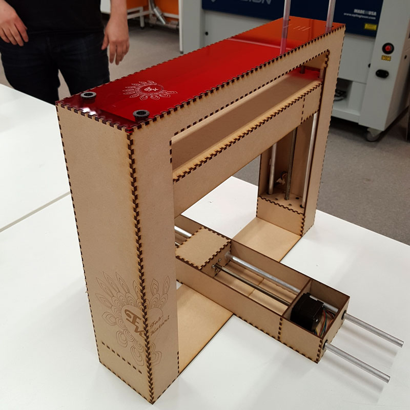
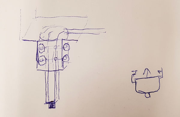
Finally, we ended up building a slightly similar structure to Roland SRM-20 milling machine where the Y- axis will move on the table, and and the X- and Z-axes will move the head. In the head part, as a measuring tool head, we considered using a mechanism familiar from a ball point pen, where the ball will slide over the surface and measure if the surface is even.
When we were considering how should we design the measuring sensor, our Fab Lab Leader Jani Ylioja told us about Piezoelectric sensors, which could have been a good idea for measuring the evenness of the surface. Our regional rewiever Bas Withagen provided us another possible idea, being a kind of button sensor, which moves over the surface by going up and down, and and every time it touches the surface it connects the circuit inside the button and sends information to Arduino about the height of the surface. The benefits of this solution is also, that it is doable in this two weeks time scope.
In the head part, we ended up creating a structure similar to a ball point pen but changing the function to be up and down moving head that will connect the circuit when touching the surface and in that way send the information on Arduino about the height of the surface.
Moreover, we decided to make our machine a modular machine. We aimed at changing the function of the machine by removable Y-axis. This way, we could utilize the same body/ structure of the machine to be for example a rack for a 3D scanner. In that case, the modular bottom part of the machine could be changed and replaced by rotatable plate, to rotate the object to be scanned, where the two other axis can take care of the shooting height and angle.
3D Modeling the Machine in Fusion 360
We wanted to see how the mechanism we considered to use would work. For that Ari 3D modelled the machine in Autodesk Fusion 360.
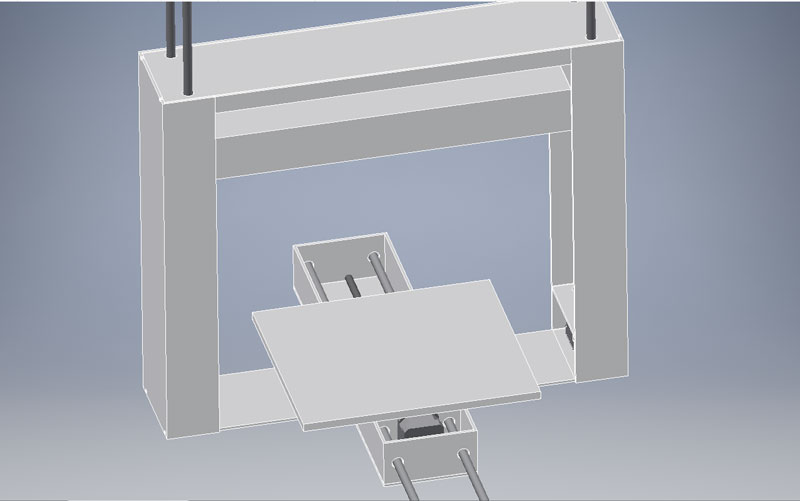
Details of the 3D Modeling can be found from Ari's Documentation.
Furthermore, Ari made a simulation of the fuctions of the mechanism.
2D Designing in Inkscape
We utilized the rods and motors that was left from the previous year Fab Academy group work, but we wanted to create a new body for the machine.
Based on Ari's 3D modelling, Jari started to unfold the model and work on the 2D cut files of the main body/ X-axis, the plate/ Y-axis and the lift/ Z-axis in Inkscape. Kati suggested that we could make the cut parts of the machine using two different materials. Also Jari had same thoughts and a similar idea to Kati's final project which is, that we are eager to see the electronics the machine has inside. This led Jari to design the top part of the machine so, that it can hold the the gestald -boards and cables over the machine and show them nicely through the transparent material.
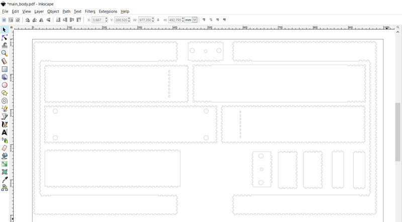
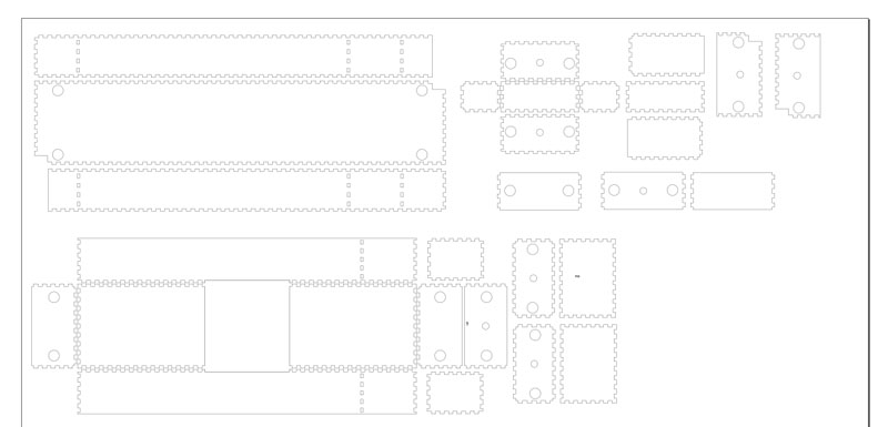
Details of the 2D Designing can be found from Jari's Documentation.
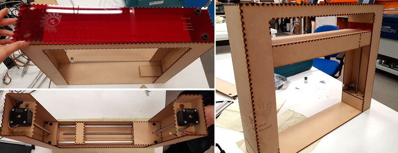
Cutting and assembling the parts
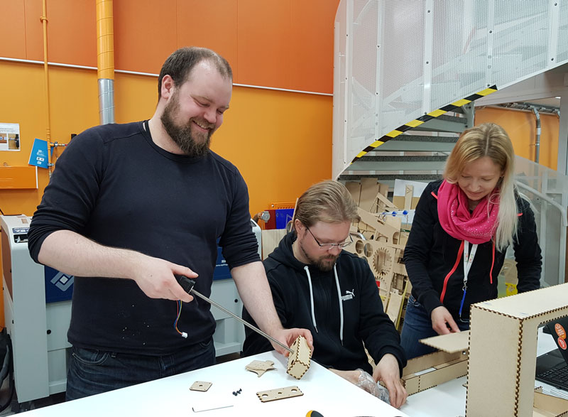
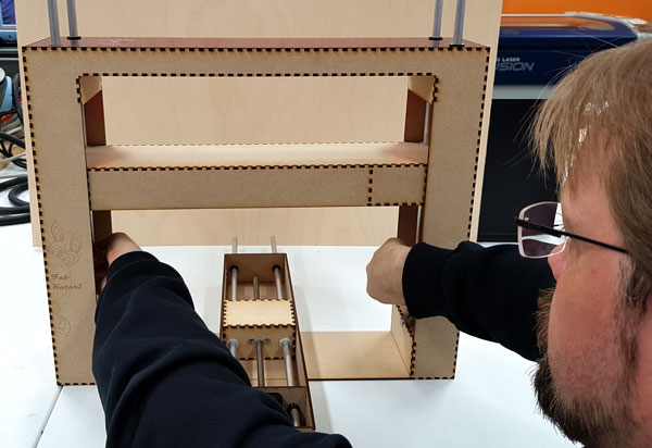
On Monday morning we were ready for cutting and assembling the parts of the machine. At first, Kati did only the vector cutting to see, if the parts work as planned, and decided to add some decorations later on after we have seen, that the mechanism works.
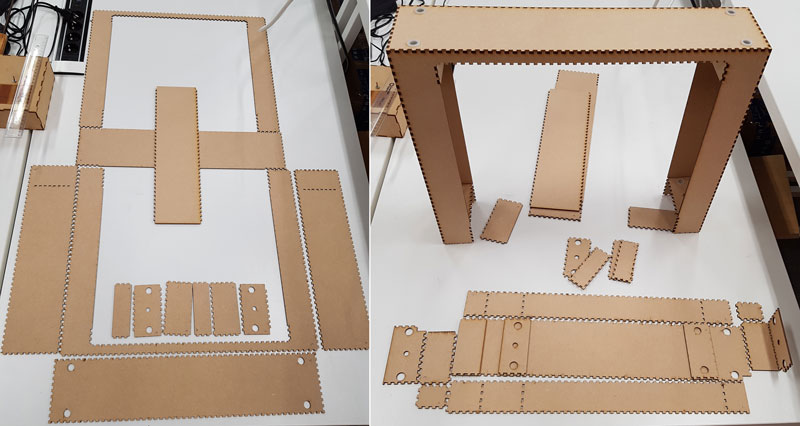
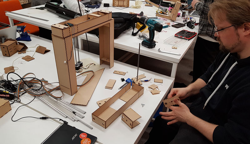
Assembling phase was enjoyable since all parts fit nicely and tight together. First, Kati constructed the cut parts to see, how should they be assembled and then we started to assemble them. Actually, all of the parts were so accurate that we did not need any glue to support the structure. Also the combination of teeth of MDF and acrylic worked great!
There was a few small mistakes in 2D -design, e.g. some of the holes for attaching the NEMA-17 stepper motors were missing. Ari fixed that by modelling the holes of the motor and cutting one of the pieces again and then, we made rest of the holes manually for avoiding the material waste.
Further, Jari increased the height of the bridge part - meant both for the cables and gestald -boards - since it was slightly too thin when the connectors were connected to the boards.
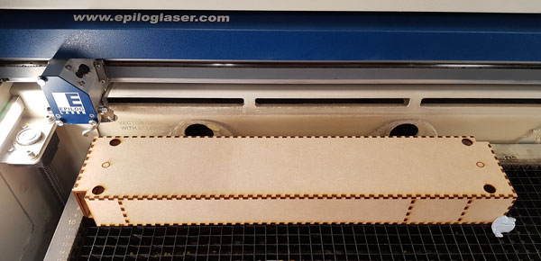
Some of the missing holes we cut by placing the whole axis on the laser cutter, so we didn't have to deassemble it:
After assembling the body of the machine, Kati designed, cut and assembled the plate part of the machine located on the Y-axis:
Graphic Designing
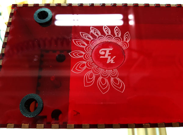
Kati wanted to personalize the machine and designed some graphic objects on the sides of it. First of all, she created a name for the machine using group members first names (Kati, Jari, Ari): Fab Katari, which in Finnish can be thought as a nickname for the device that checks something - in this case, the machine checks eveness of the surface.
Secondly, she created a logo for the machine:
![]()
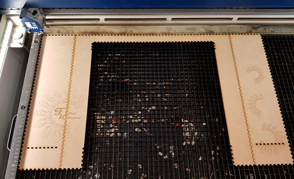
Then, she engraved the graphics on sides of the machine, as well as on the acrylic part on top of it. We did not have time for making any real 3D -design, so the picture is simply engraved around the corner by unfolding the parts to be engraved. Engraving worked fine otherwise, but one small mistake appeared during the cutting, where the laser cutter cut one circle on top of the machine which it should have been only engraved. When checking the thickness of the line in the design file it was 0,12 mm, not 0,02 mm which is the cutting thickness for lines, so it is an unsolved mystery so far why it was cut instead of engraved.
![]()
Details of the 2D and Graphic Designing can be found from Kati's Documentation.
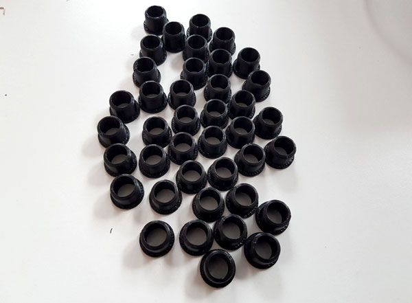
3D Designing and printing linear bearings
We needed quite a many linear bearings for our machine, 40 in total, and suddenly we ran out of them. We considered making quite quickly new ones, which Ari designed with Autodesk Inventor. Because all of the printers in use were reserved, Ari tried to print one linear bearing with Leapfrog Creatr, which is not in active use at the moment, but it failed (maybe the printer has became loose). Fortunately, the second trial with Sindoh 3DWOX, and also the rest of the pieces Ari printed with Stratasys Fortus 380mc worked just fine. Now, we can use the self fabbed linear bearings for our machine.
However, we faced next problem with the printed pieces during assembling phase, where some of them wored perfectly but some of them were awfully tight, even the quality of them looked very fine. The reason of the issue was found when Ari measured the rods with a caliper, which indicated that the probmlem was in the rods, which diameter seemed to vary between 9,30-9,80 mm. The one that Ari had measured for modelling was 9,50 mm so, some of the rods worked fine but for some of them we had to make new pieces of linear bearings.
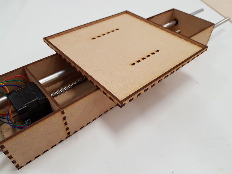
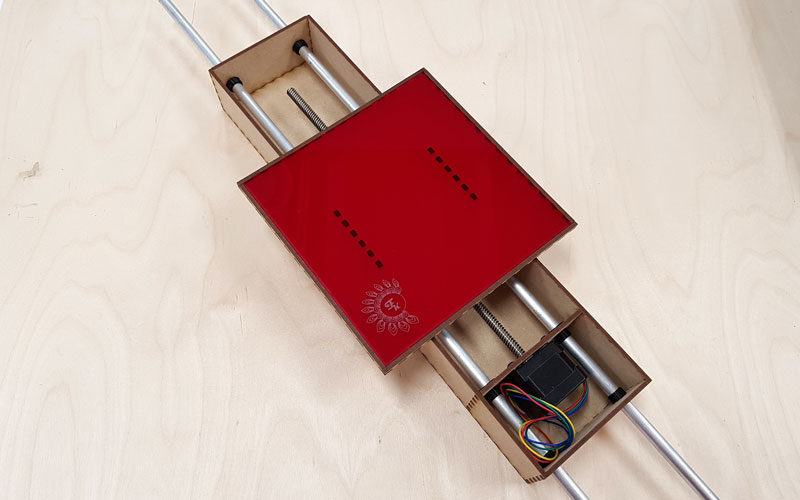
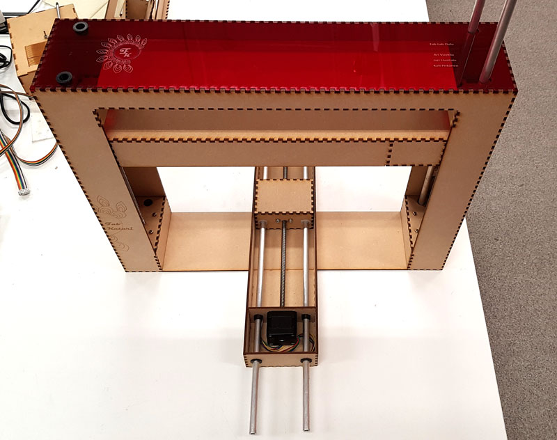
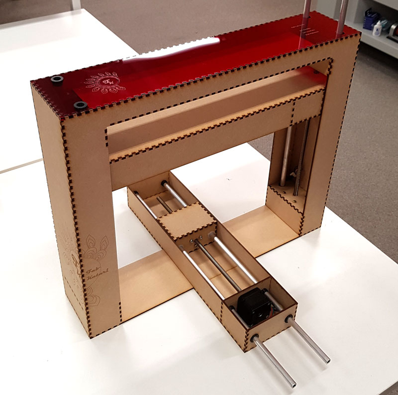
Details of the Measuring Machine
Here are some details of the machine:
Video of the machine motion in X, Y and Z directions
Files
Here are the files of mechanical design:
- All of the 3D modeling files
- Laser cutting files in svg format
- Main body laser cutting file in pdf format
- Lift laser cutting file in pdf format
- Y-axis laser cutting file in pdf format
- Laser cutting file of the Plate in Y-axis in svg format
- Laser cutting file of the Plate in Y-axis in pdf format
- Graphic Design of Top and Plate acrylic parts in svg format
- Graphic Design of Top and Plate acrylic parts in pdf format
- Graphic Design of Machine Body MDF parts in svg format
- Graphic Design of Machine Body MDF parts in pdf format