Week6
3D scanning and printing
additive vs subtractive processes
Assignment:
Characterize 3D printer
You can see the complete documentation of group assignments on the opendot website at this LINK.
For the characterization of the 3d printer we choose and download .STL files of this test collection and of another test on Thingiverse because on the gallery there are more test images and it's funny to see different result with different printers.
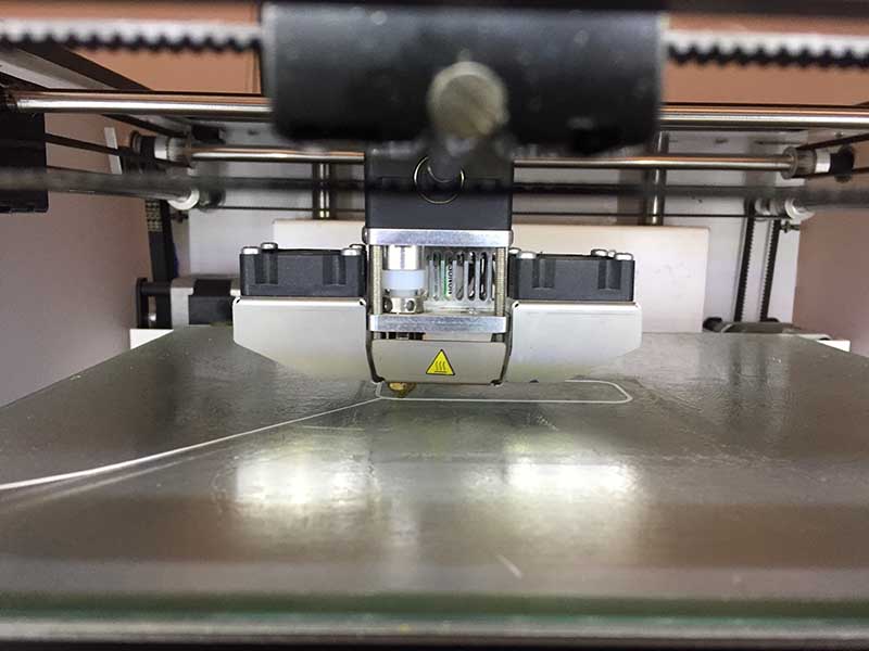
We create the gcode from CURA software and print all the test with Ultimaker 2+ printer. In Opendot there are other printer, you can see it on this page.
The latest version of Cura is very different from the previous ones but using it with Ultimaker2+ the profiles set by default are very effective. This is useful for those who have never printed. For the settings of "smanettoni" perhaps the previous version of the software was more convenient to manage the advanced settings.
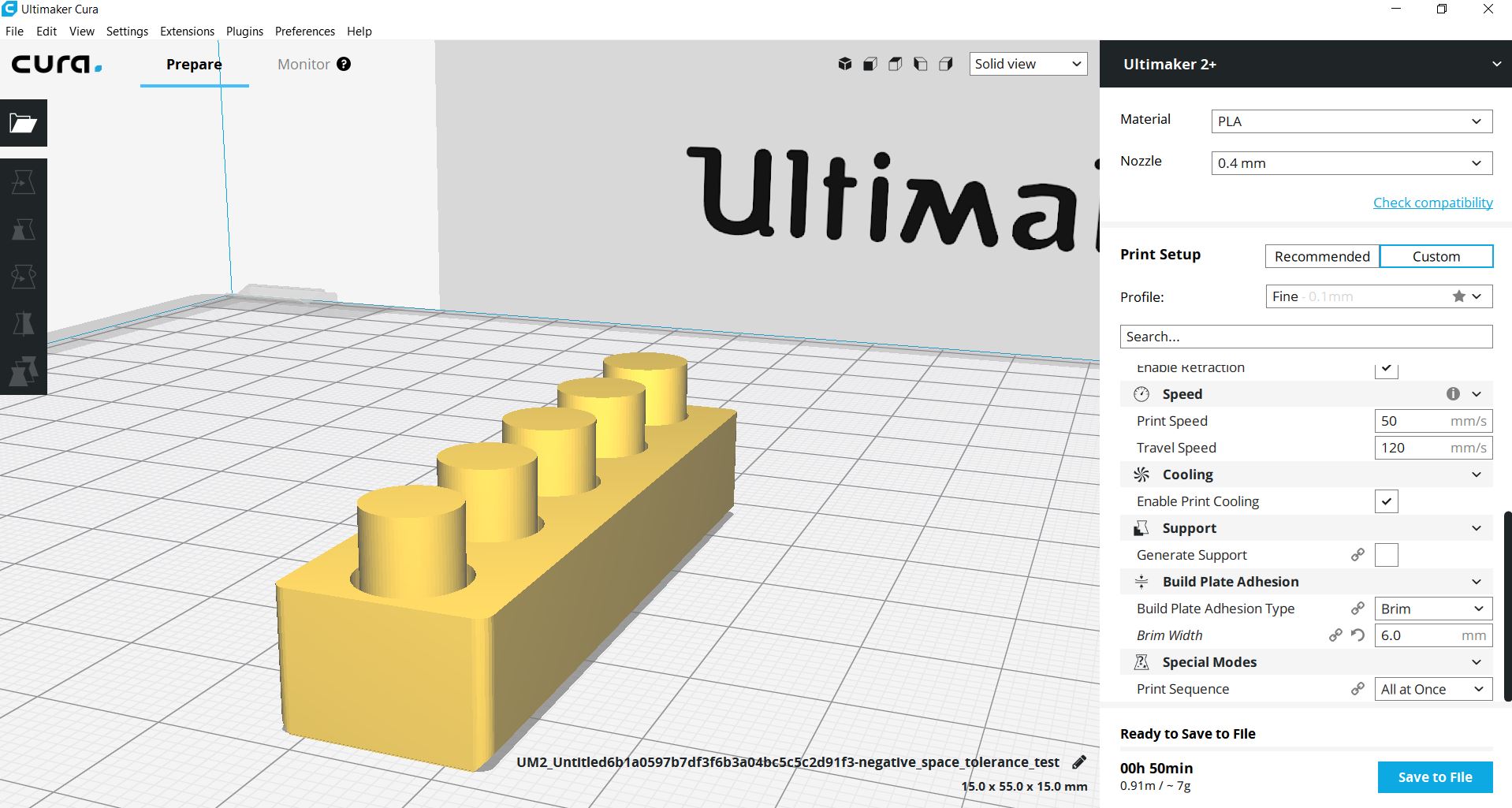
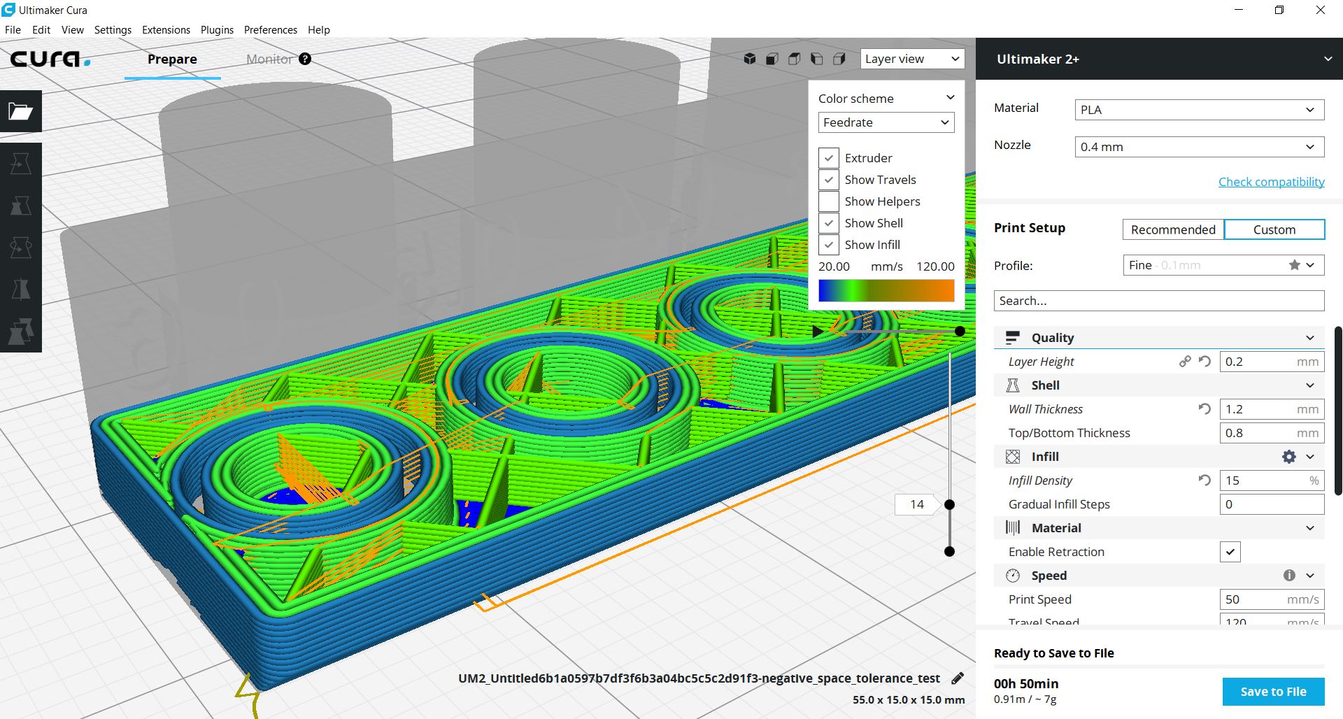
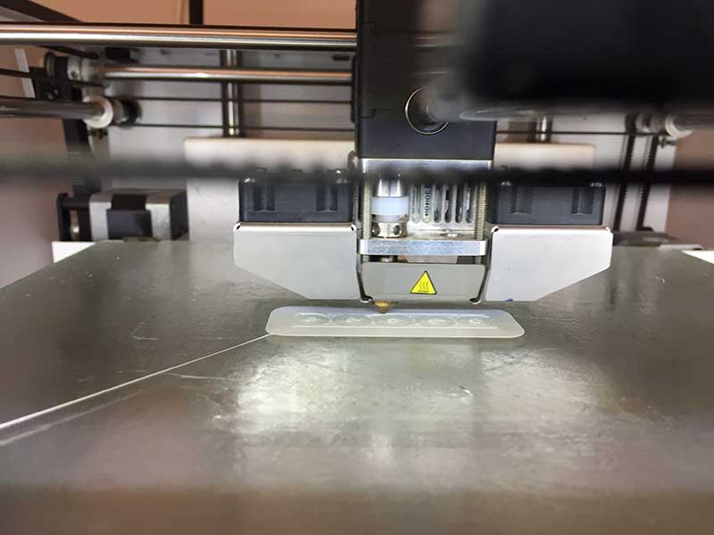
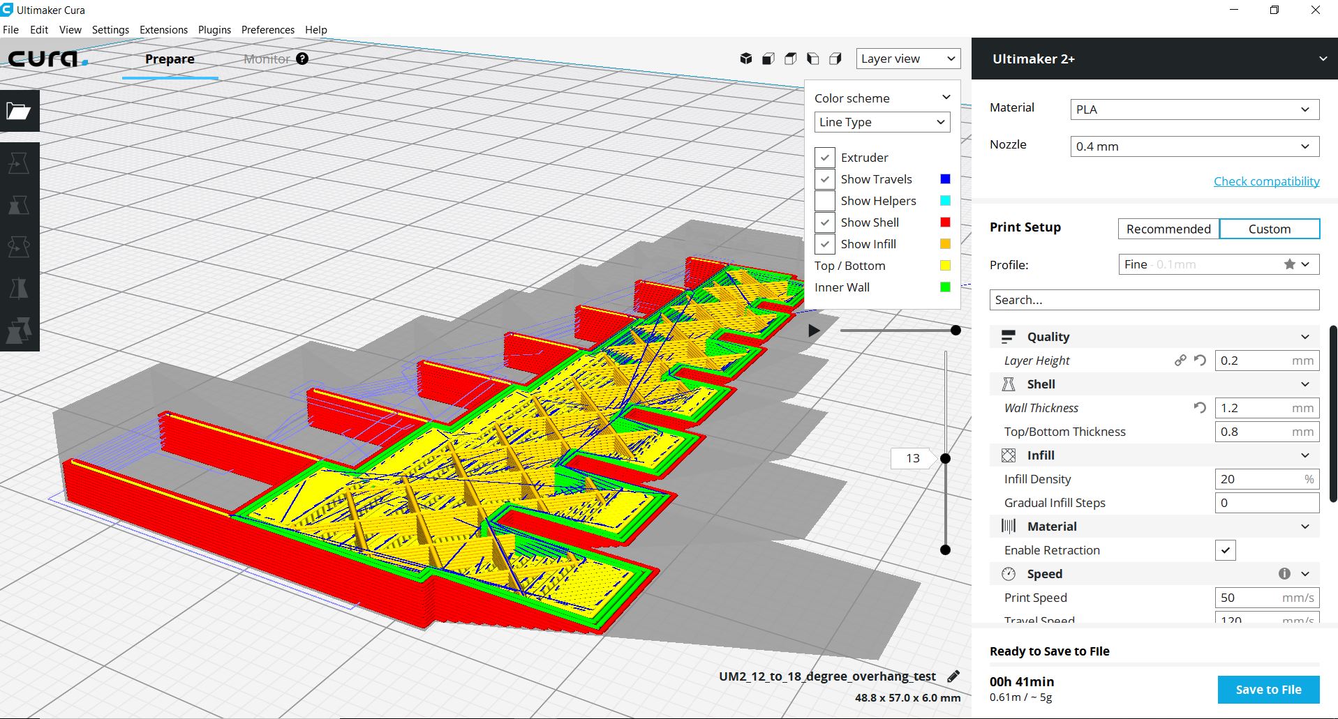
I decided to print this block which is used to quantify the interference between two printed pieces. I used the settings you see in the screenshots.
 Next time it was better not to use the brim.
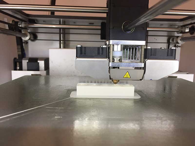
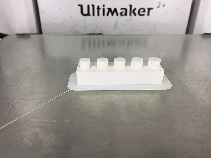
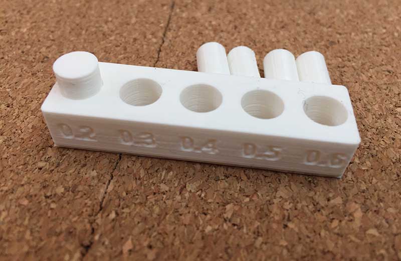 The piece with 0.2 mm offset was melted to the base. So with this test the limit for offset beetween 2 pieces is 0.3 mm, ore more!
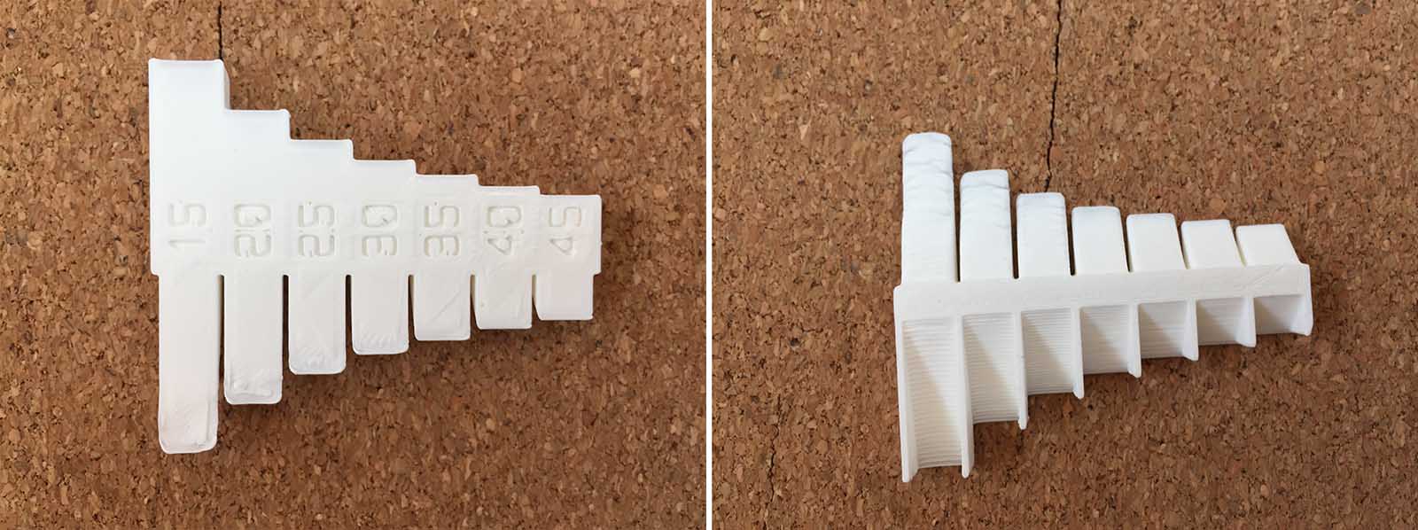
The second piece I printed was used instead to understand the limit of the undercuts that the printer could make.
 I used the settings you see in the screenshots.
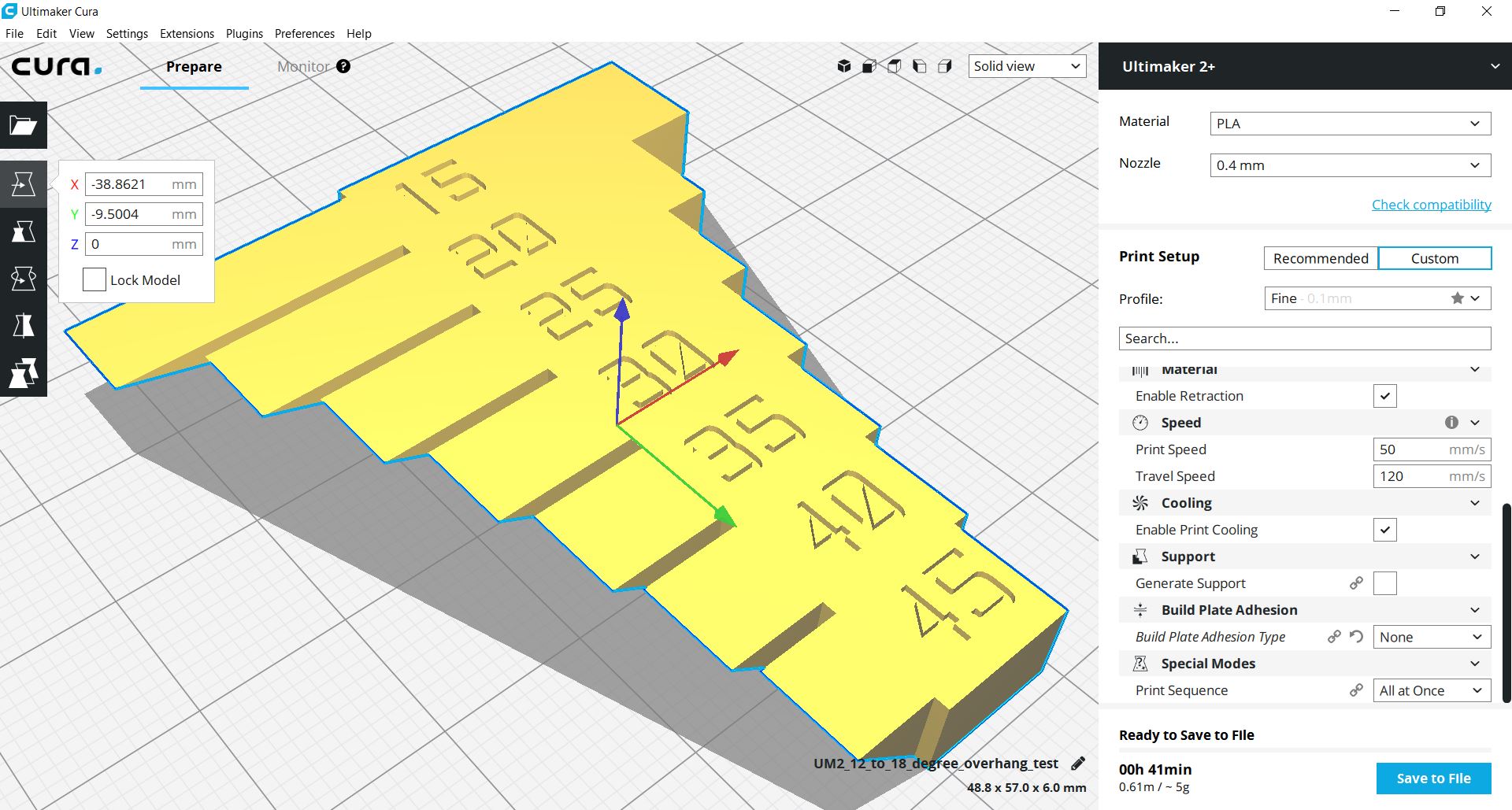 The cantilever part worked well up to 30 degrees, then started to warp. In this case I think that the dimensions of the piece influence a lot.
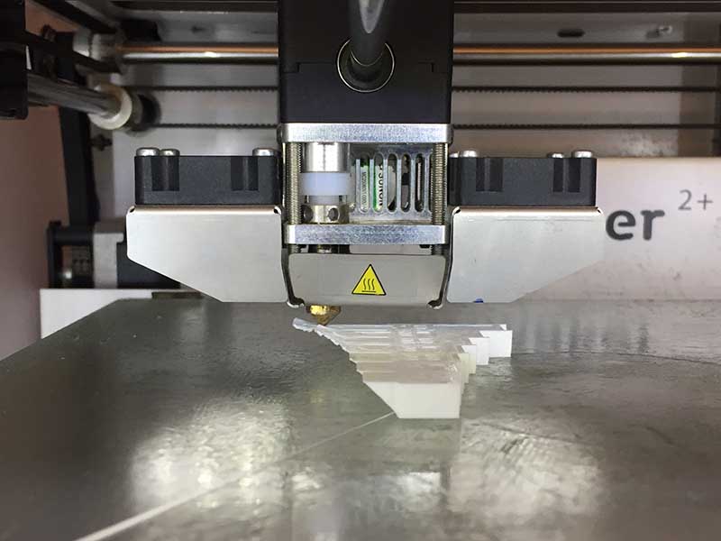 On the side where there are bridges it worked well up to 15 degrees!!
Design and 3D print an object (small, few cm) that could not be made subtractively
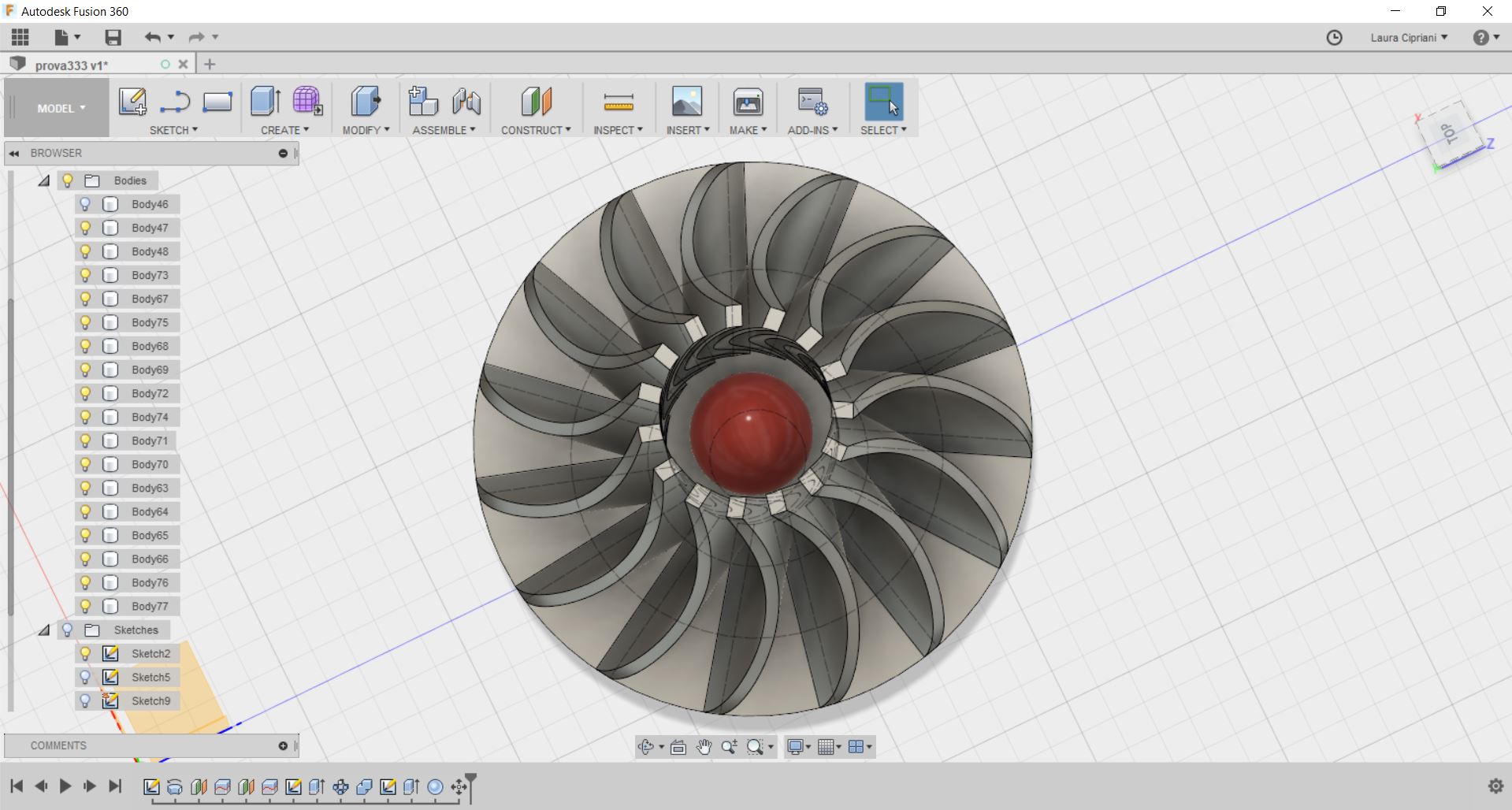
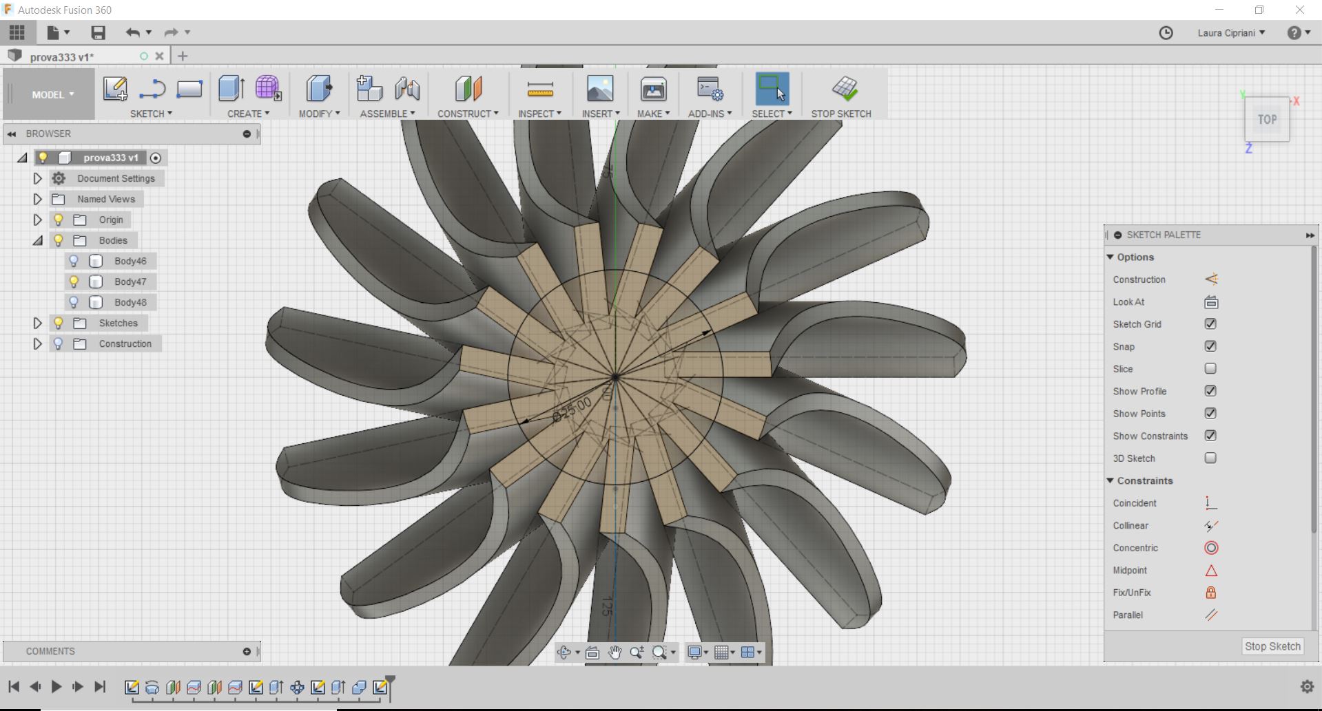
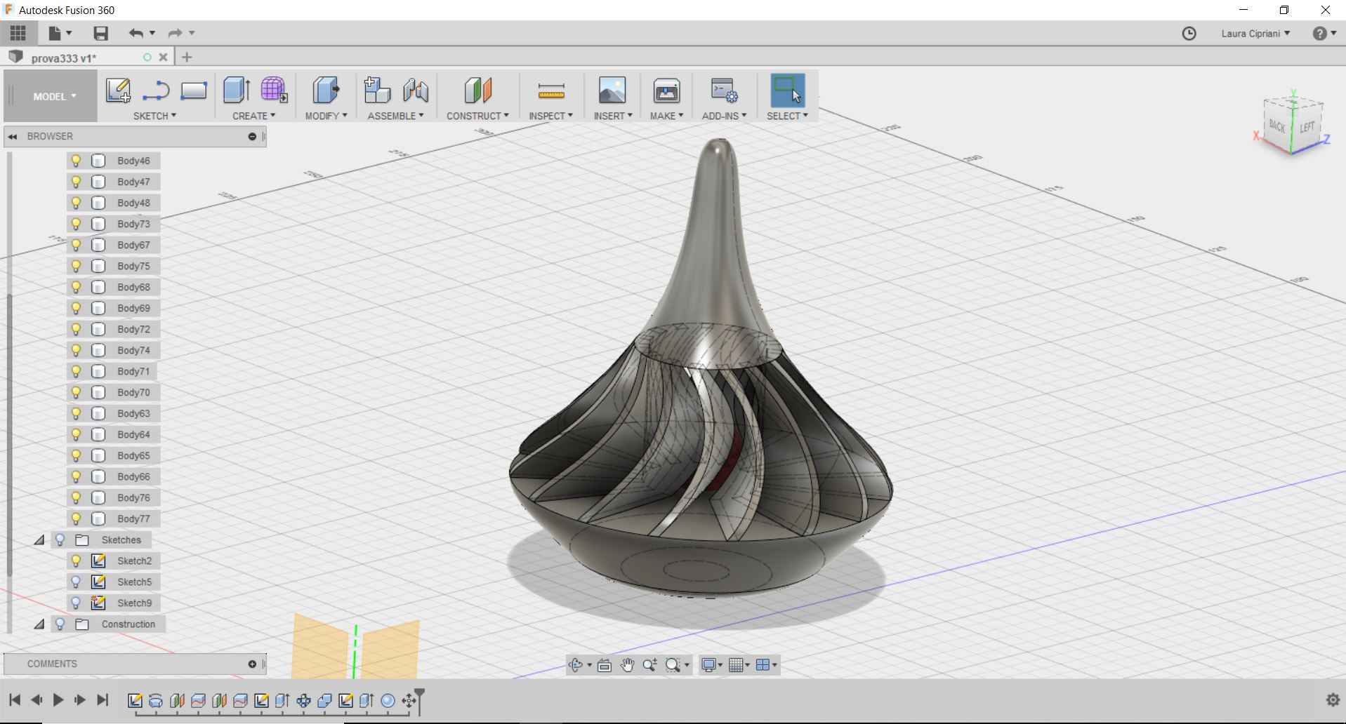
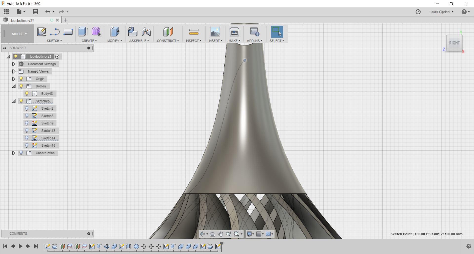
For this exercise I decided to model with Fusion360
a small rattle for children (which is also a spinning top!).
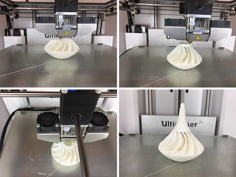 I chose it because only with this technology it is possible to create a sphere inside that can't go out and it makes a little rattle if you shake the piece.
 (My mom calls this object "Borbolino" that's why the file you download will have this name ...)
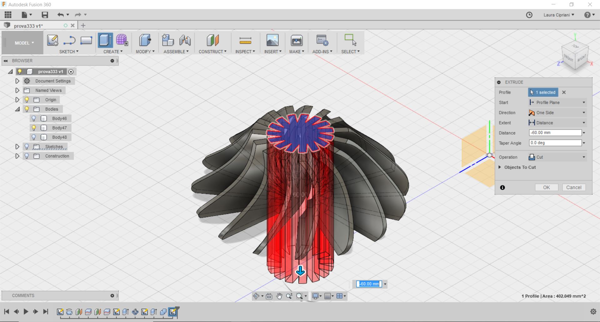
 I also emptied the piece handle to reduce printing times
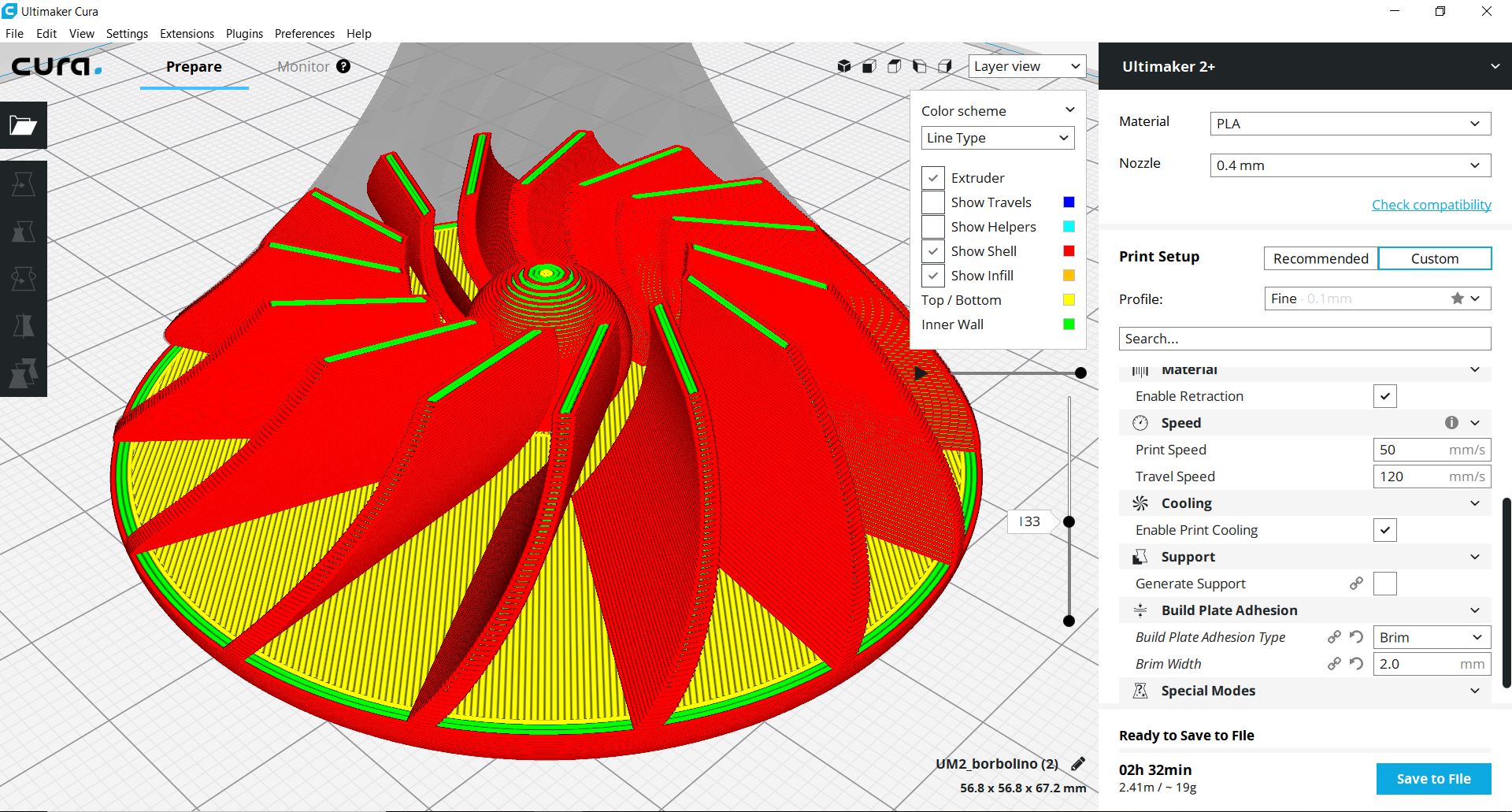
 To speed up printing I printed the first model with a 75% scale
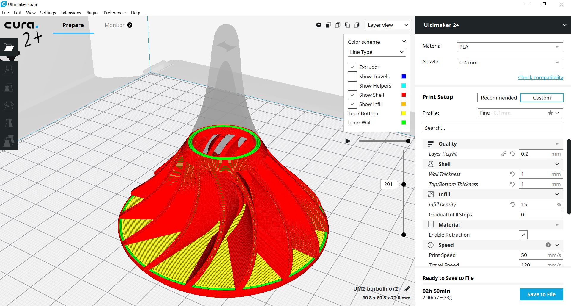 I used the print parameters you see in the screenshots
fabacademy2018:3d printing test from lauracip on Vimeo.
This production process is very interesting I believe that a designer can deal with this technology in two ways:
3D scanning
3D scanning with Scanect
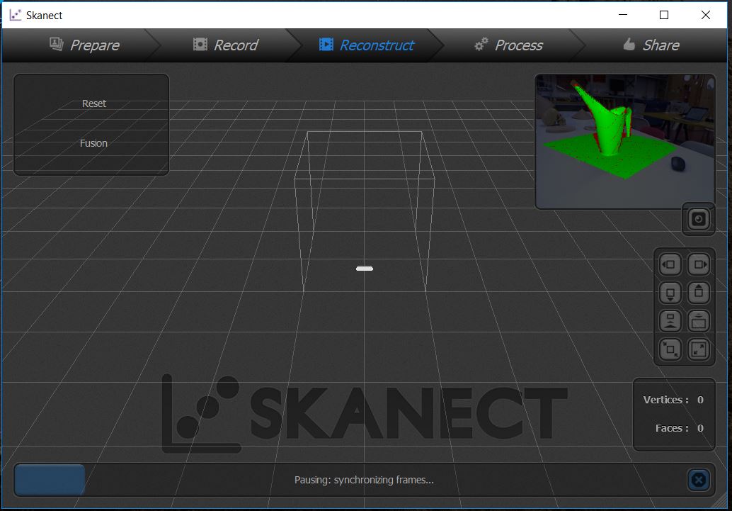
For the scan I used a XBOX Kinect with the free version of the
Skanect software.
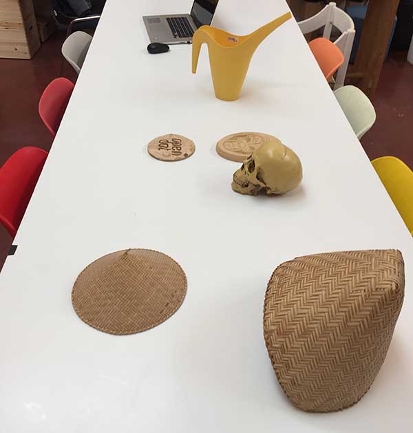 I choosed different objet (in form and material) for understand the logic of the scanner. I had used "Scan in a box" (structured light scanner) for another project last year and I tried "3D sense" scanner, but I never used this system before.
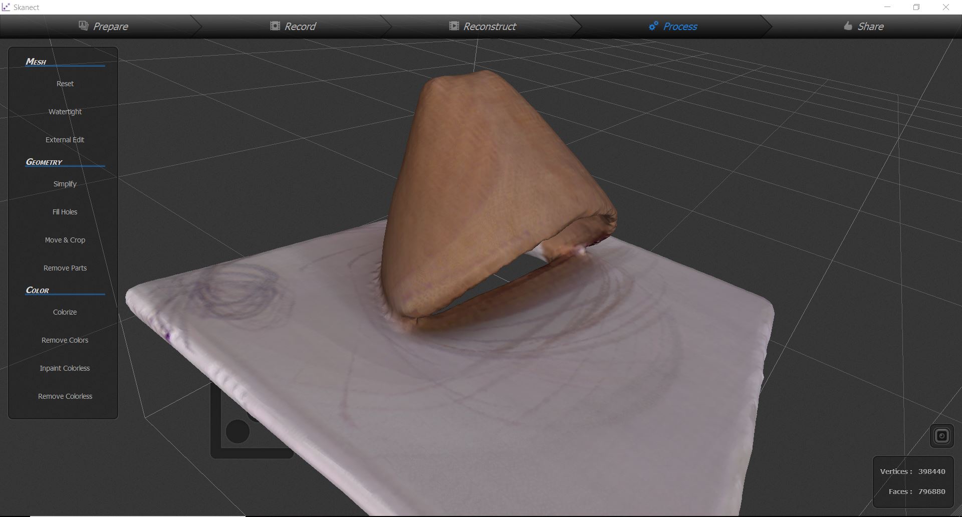
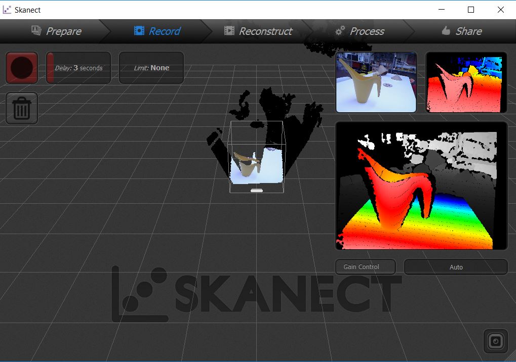 The software is very simple but has very limited functions. On small objects (about 10 cm) this does not work very well.
 Light, material and the surrounding environment have a great influence.
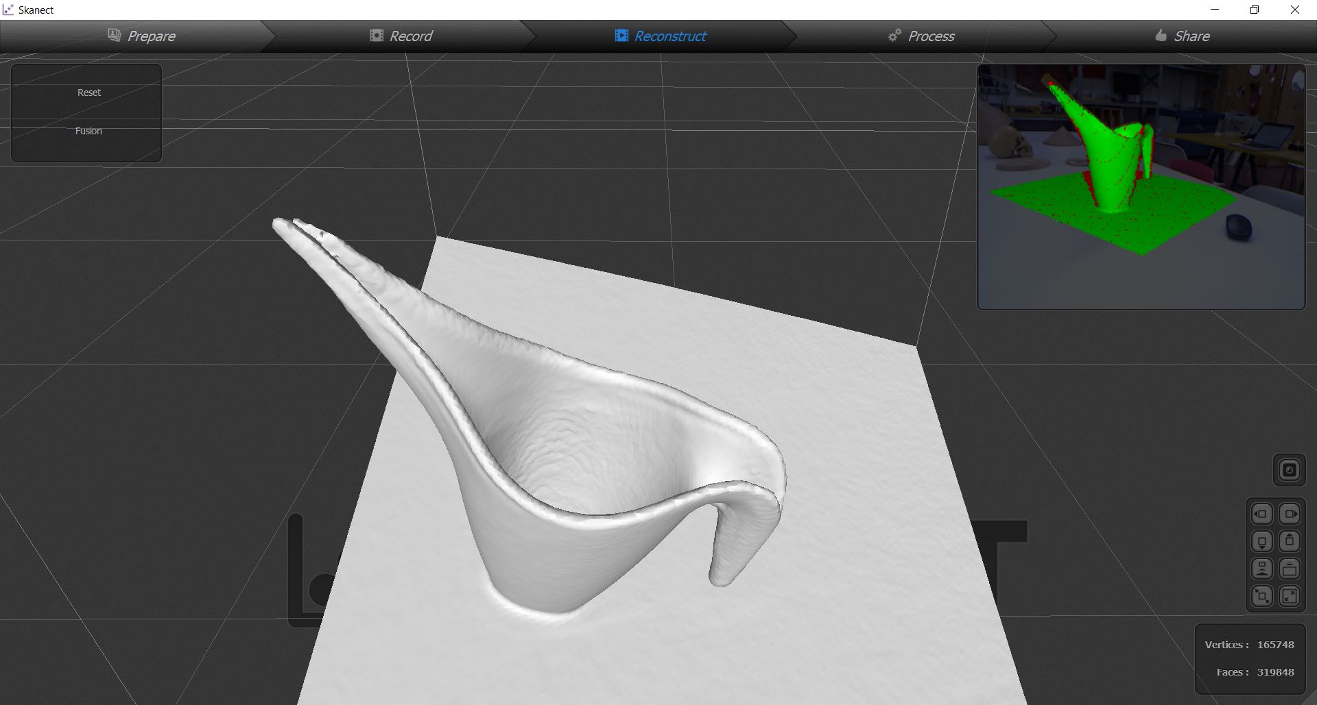
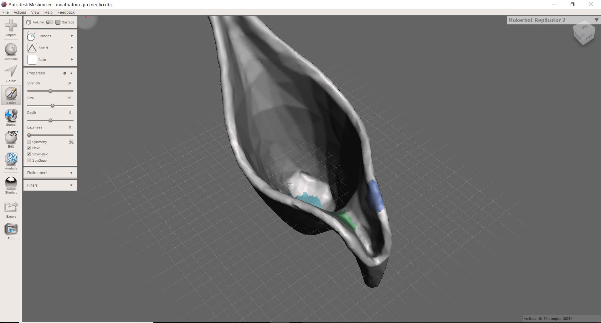
 The software has a series of commands to correct the mesh and close the holes but I prefer to use meshmixer.
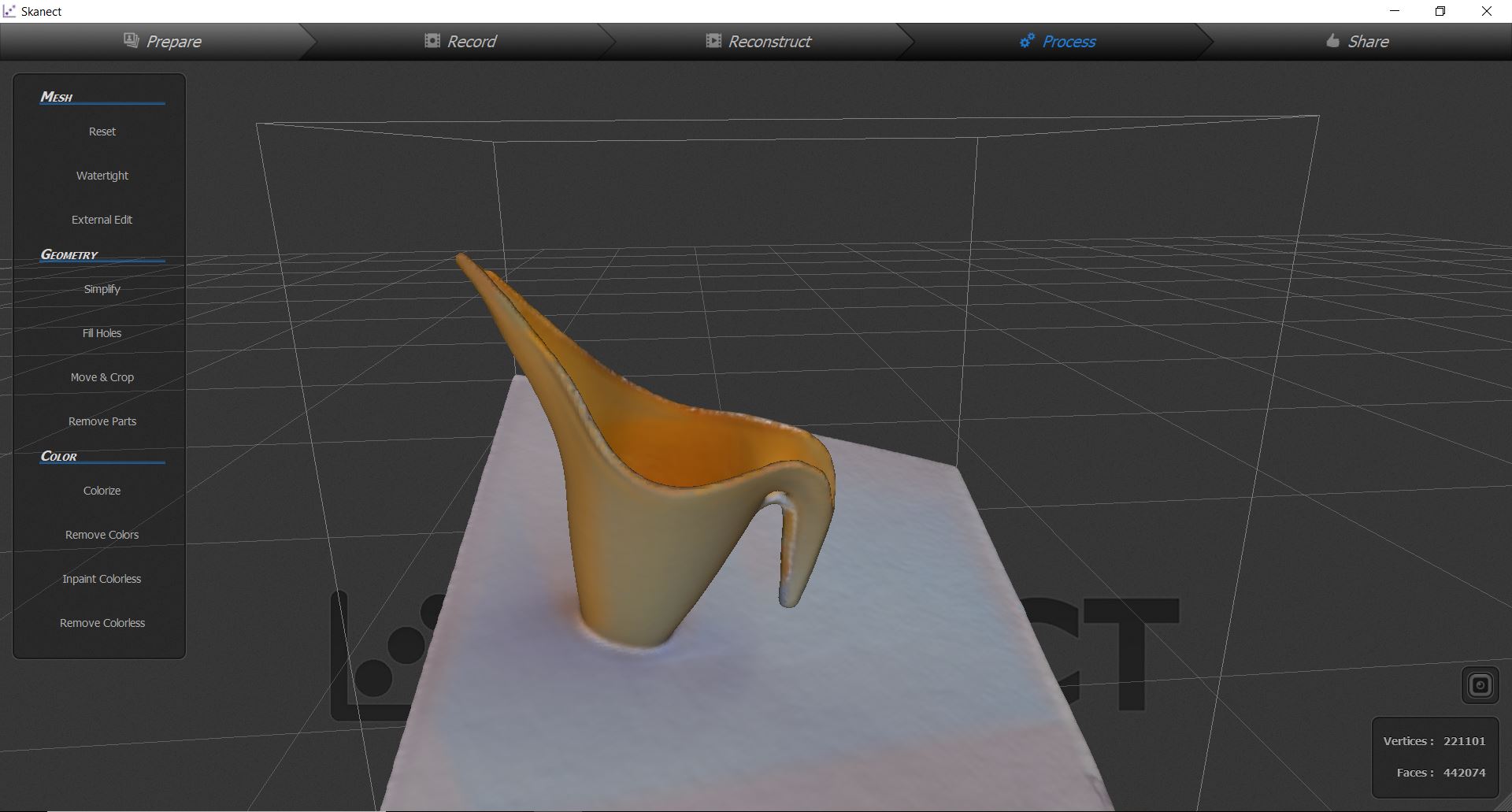
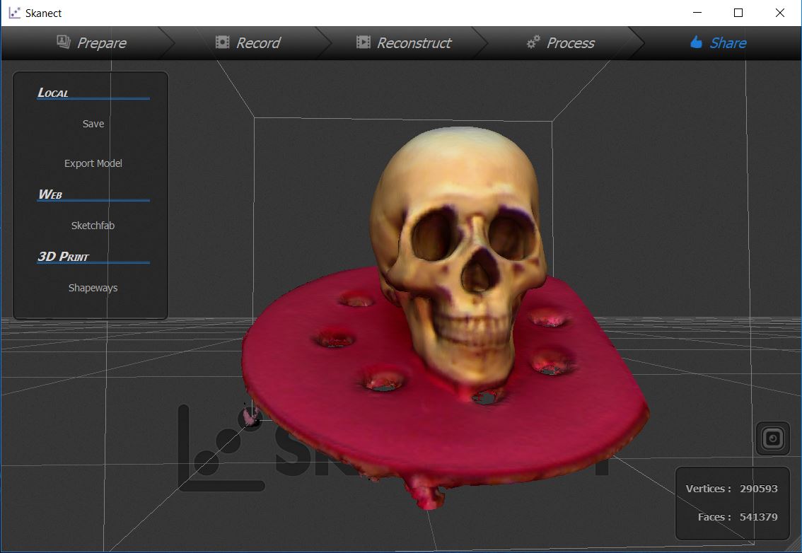
 The object that has come better is our skull, resting on one of the stools of the lab!
Photogrammetry with 3DF Zephyr Free
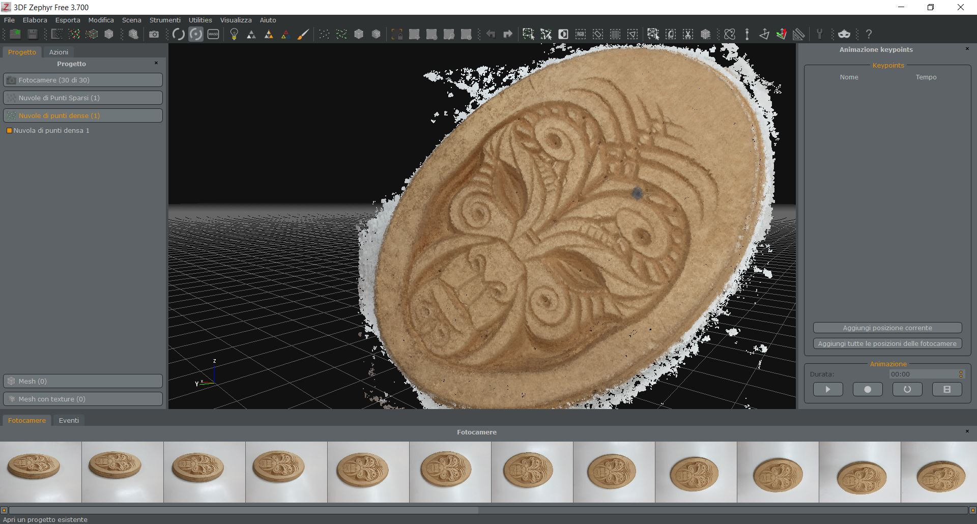
I also did a photogrammetry test. I decided to try new software 3DF Zephyr. Is very similar to Photoscan, less performing but has a very good free version.
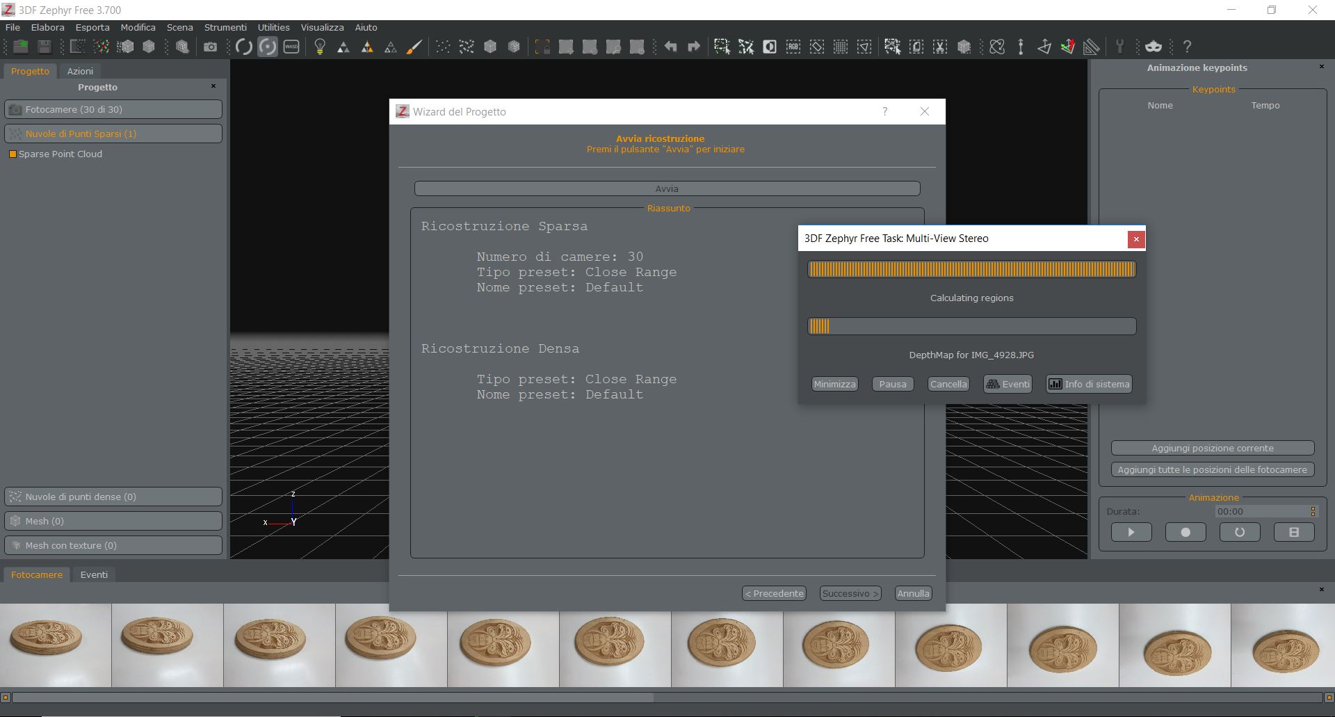 Step 1: uploading photographs (Photography guide here.)
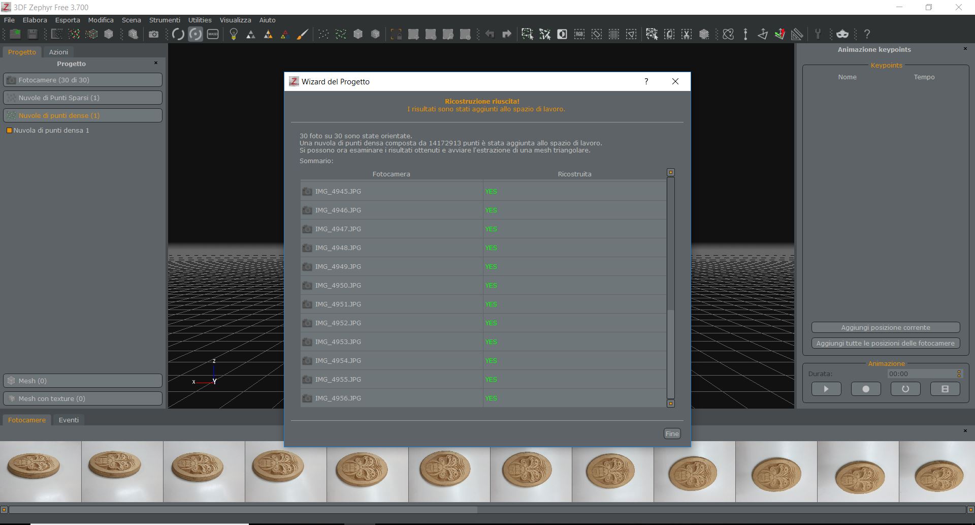 Step 2: Dense cloud point generation
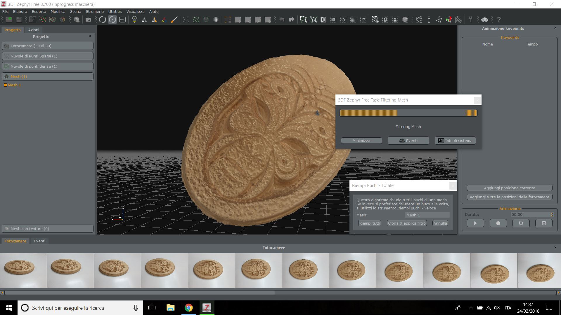
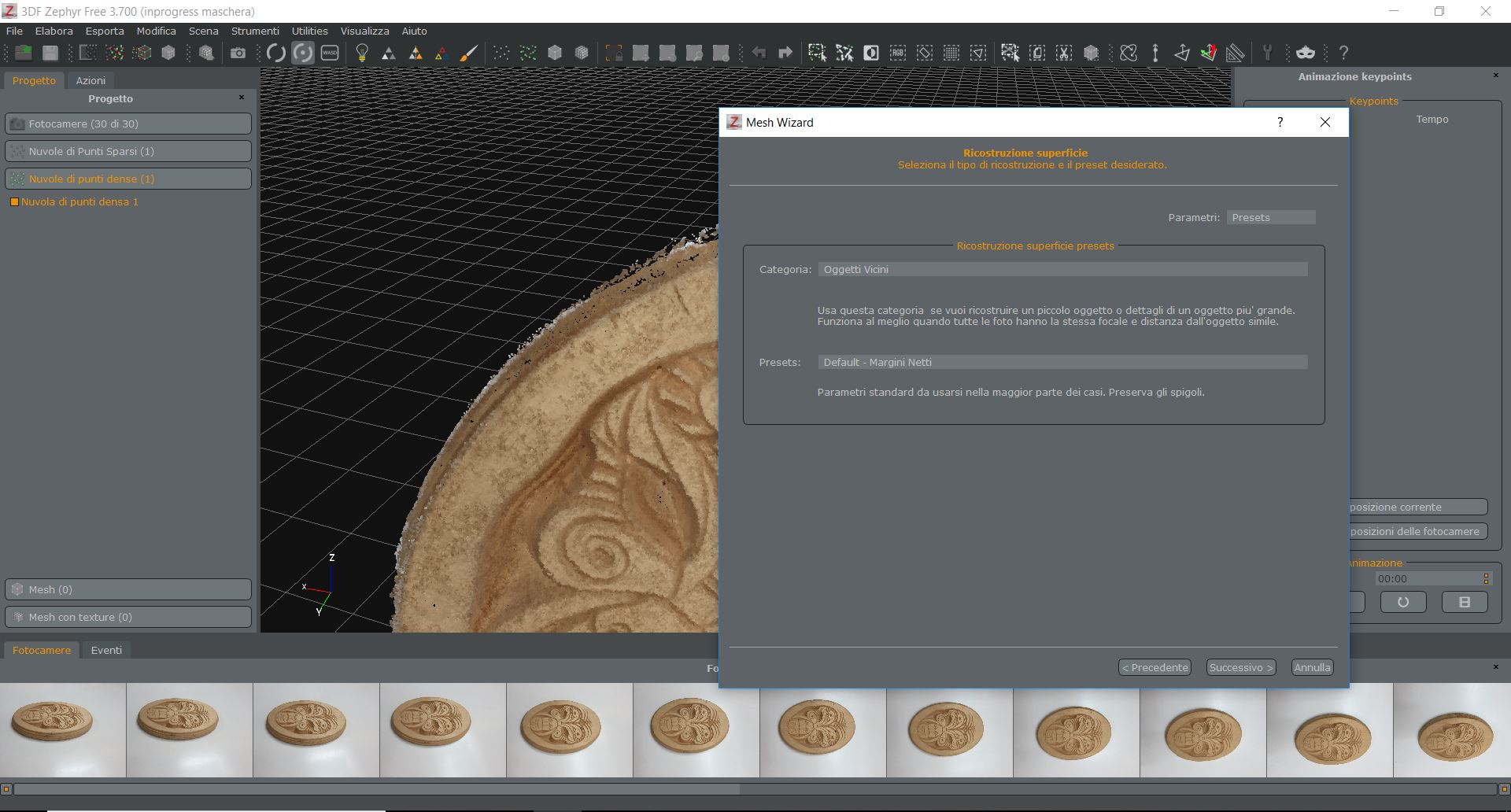 Step 3: mesh generation
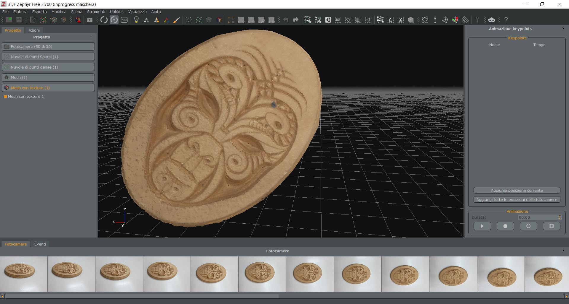
 Step 4: mesh with texture generation
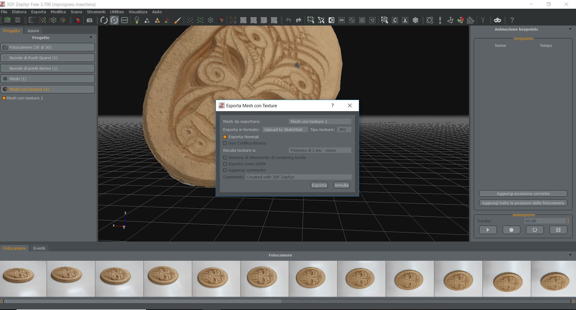
 Step 5: Export
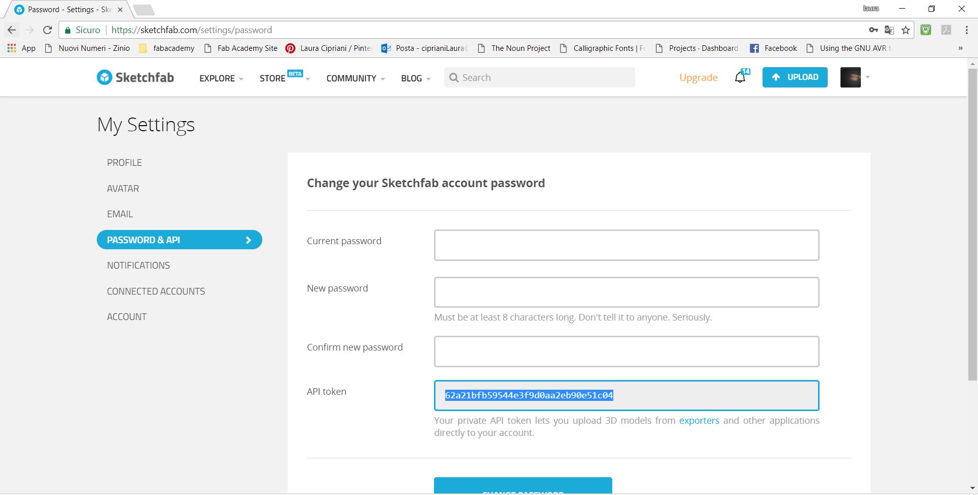
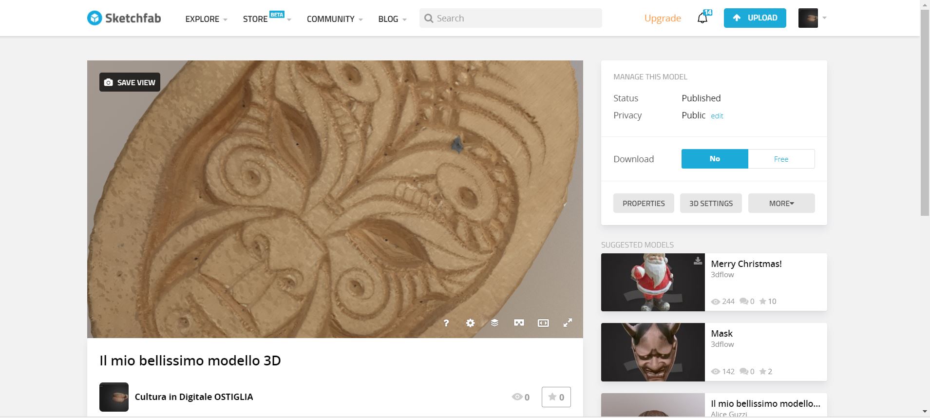
 Step 6: Upload directly on Sketchfab
Before this experience I had to do a project with a school concerning: photogrammetry, scanning and 3D printing of cultural heritage. In that context I had the chance to try out different photogrammetric software and a structured light scanner: Scan in a box.
I believe that these equipment used for teaching purposes are very effective, when it is necessary to make the transition for professional use is perhaps no longer enough. A practical example: Zephyr is free software, if the goal is to use it to create a digital model of a work and upload it to the platform, it works very well. Already for printing, the mesh and the STL file exported by this software are often corrupt or give import problems in other software.
If you choose to work with Photoscan the situation changes a lot, the level of complexity is greater but also the precision.
I believe that the potential of these technologies is very high and knowing (and having tried them a bit) I find it useful to understand what kind of equipment to choose according to the project that I will have to do.