Week11
Input device
magnetic field
Assignment:
Measure something: add a sensor to a microcontroller board that you have designed and read it:
You can see the complete documentation of group assignments on the opendot website at this LINK.
Intro
For the week of input device I decided to focus on what could be useful for the final project.
This was not easy at all: I had to imagine all the components to be inserted on the board, both for input and output.
I started thinking about what could be the most suitable sensor (sensible, cheap and easy to manage) to solve the problem "blocking the drawers" of my kit.
This requirement is useful considering the context in which the object will be inserted.
Enrico and Francesco helped me to think about all the electronics related to the project, and how it could work synergistically with the part of electronics that Francesco will deal with in his final project that will be integrated into the upper part of the drawer.
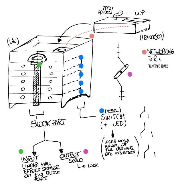
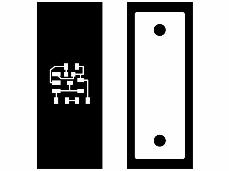
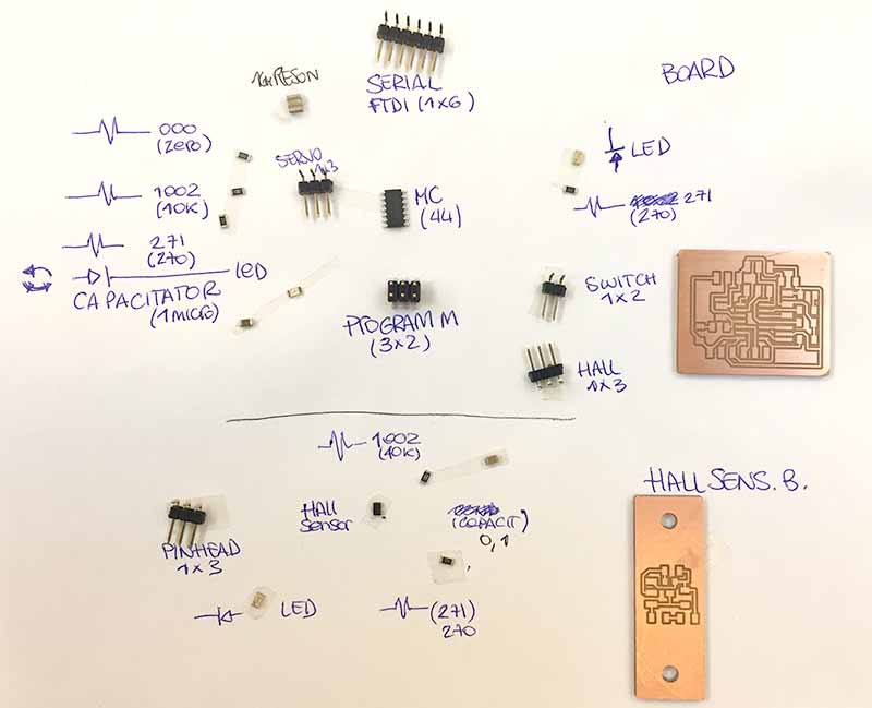
Hall sensor BOARD

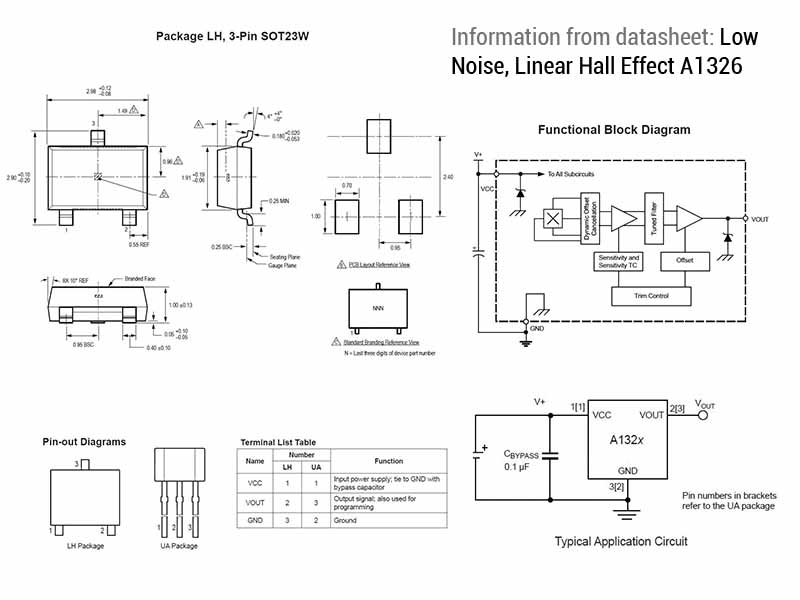
I choose this A1326 hall sensor and extract some information from datasheet.
Then I started to draw the schematic in Eagle and to follow I connected everything. I have provided 4 holes to attach the card to the piece
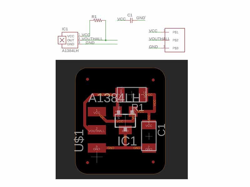
But the 4 holes were too small so I decided to make two large ones to better facilitate fixing to the final project.
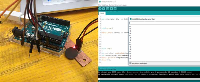
I test it with Arduino and it's works.
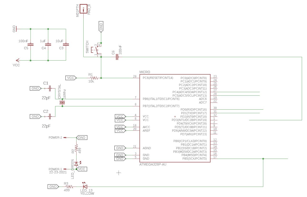
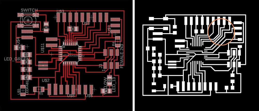
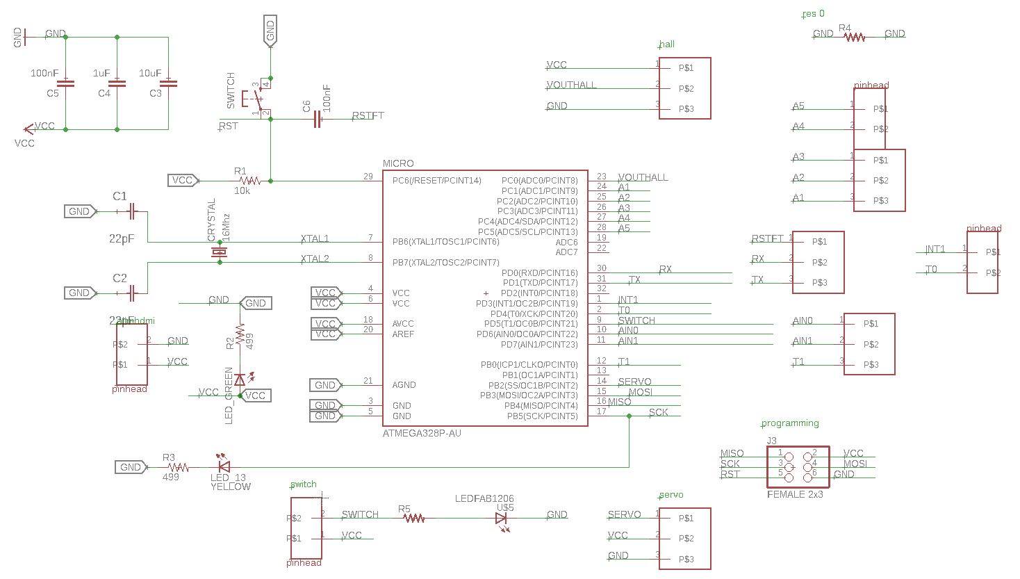
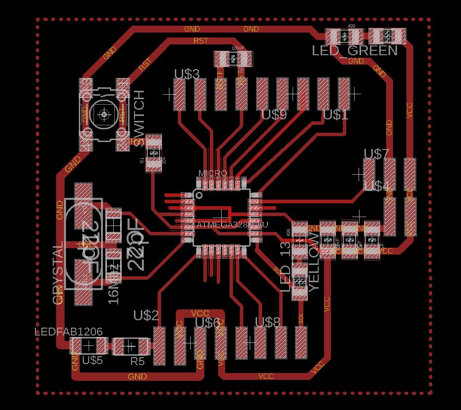
MAIN BOARD: version 1
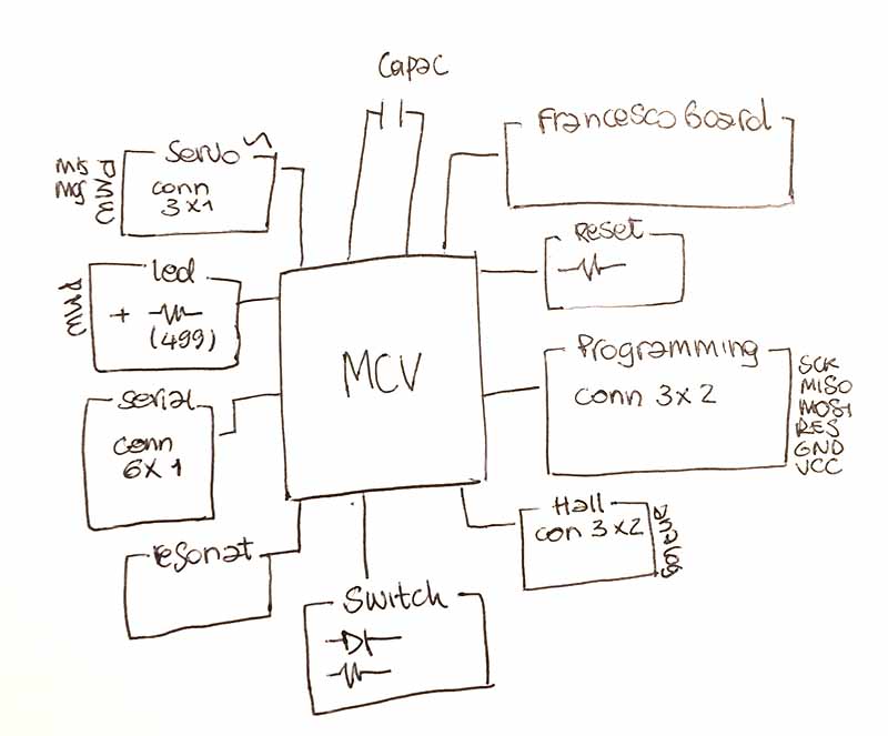
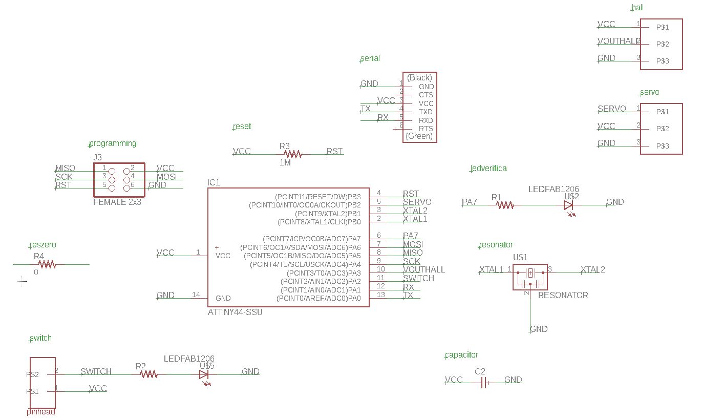
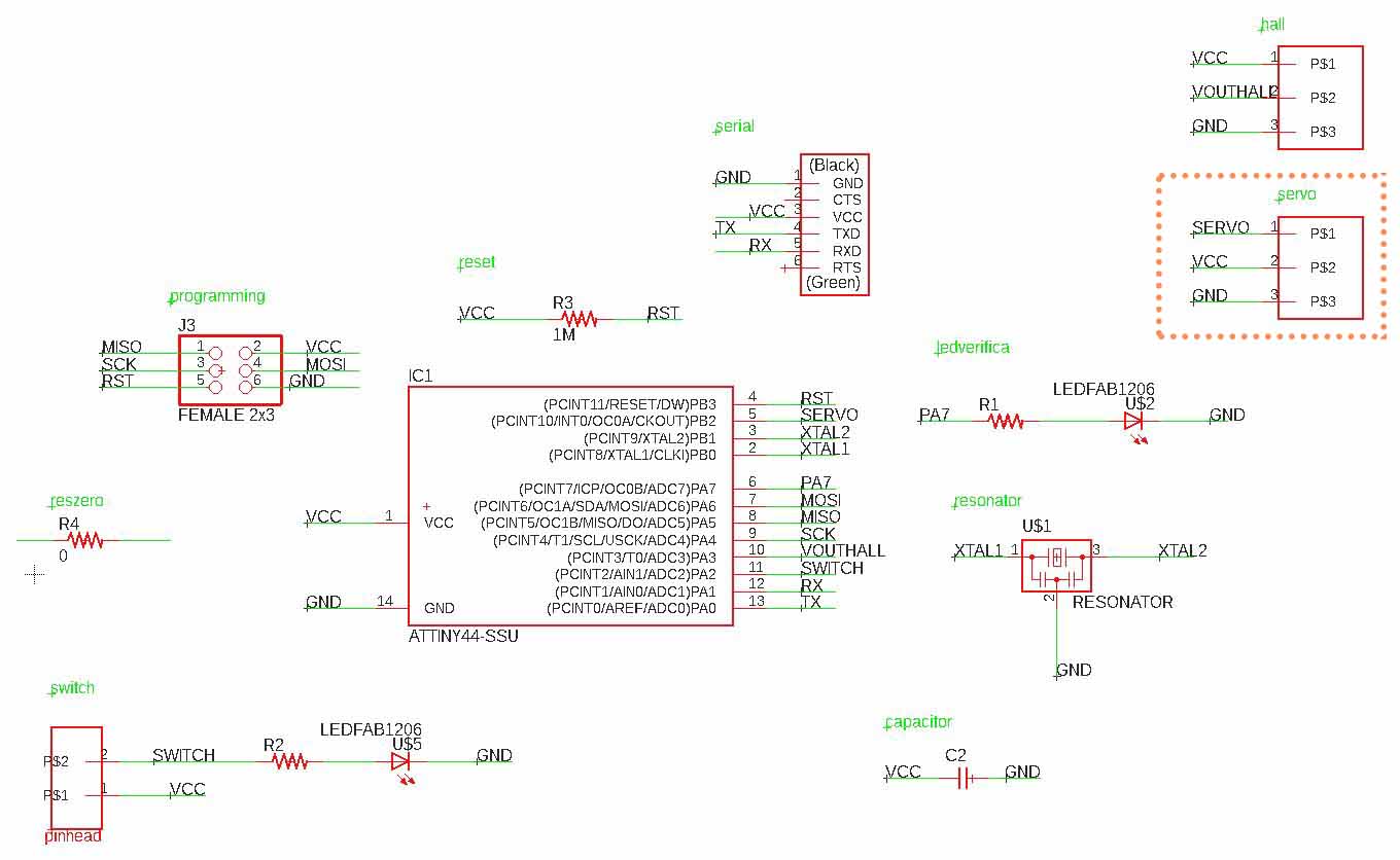
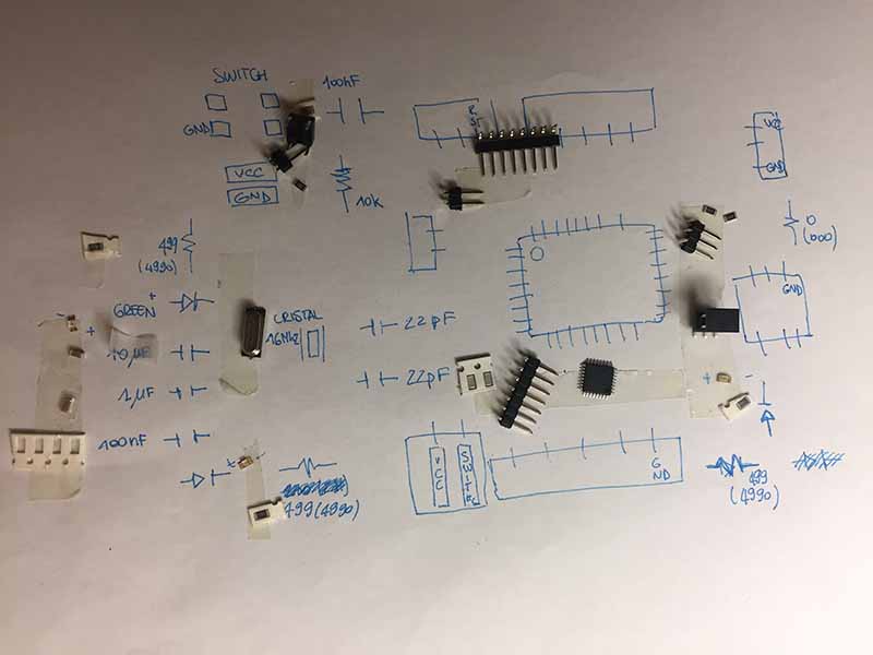
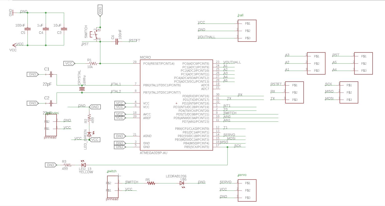
Before starting I schematized the board dividing it into logical blocks.
Being able to make the slopes for this board was quite complicated. I had to design custom connectors in Eagle, but the VCC still had to be lifted, so as a last resort I used a zero resistance in the schematic.
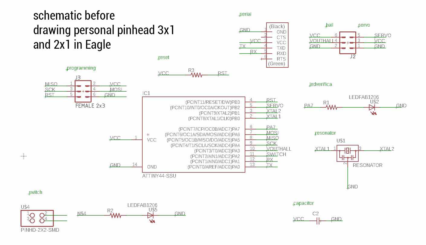
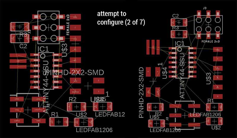
Schematic after drawing personal components: It's work better.
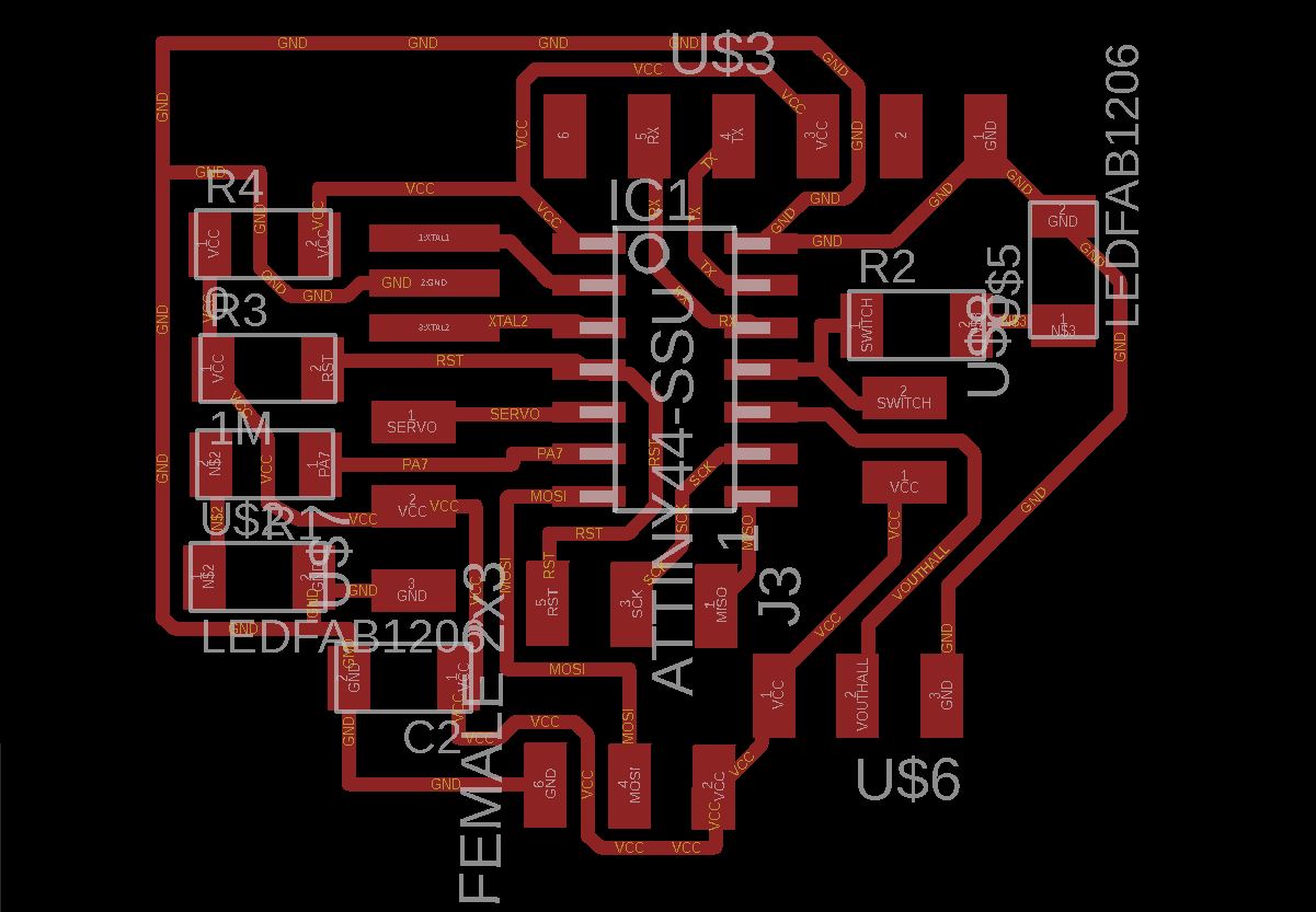
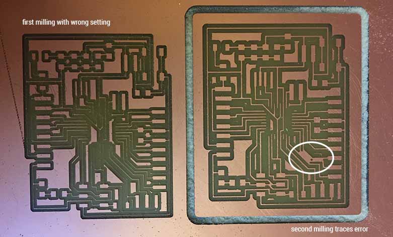
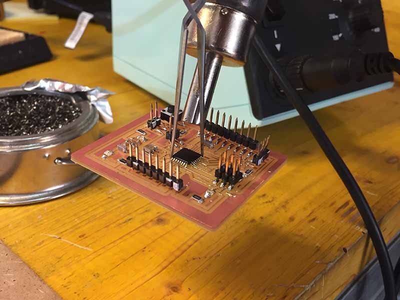
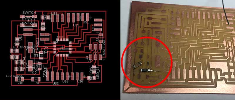
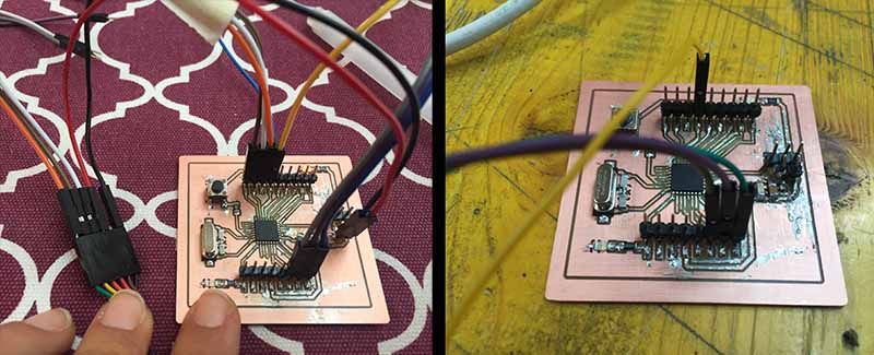
FIRST MILLING
When I tried to connect the cables to the SPI connector, part of the traces were skipped, together with the 3x1 connector dedicated to the hall sensor.
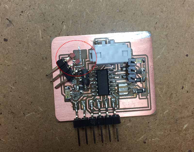
Thanks to the help of Enrico, we managed to attach the connector and the traces, apparently correctly.
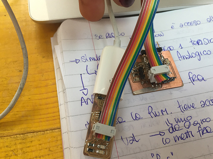
TEST IT (board one)
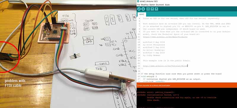
In order not to waste time I decided to try anyway to test hall sensor with my board when it will be glued. At the first connection to the PC the board started to emit smoke and to heat up.
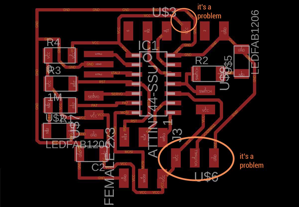
DEBUGGING PART 1
 Then I started testing the traces again and I realized that there were two problems:
DEBUGGING PART 2
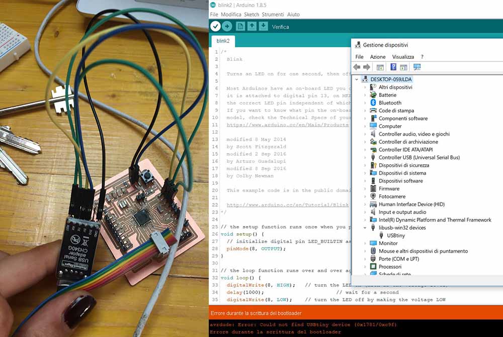
When I tried again to program it with an IDE of arduino, he continued to give errors:
DEBUGGING PART 3
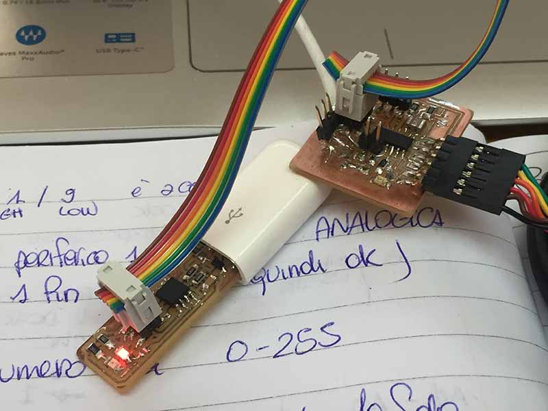
Victorious we tried again:
DEBUGGING PART 4
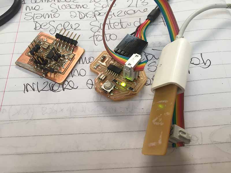
As a last option it could be a problem of the programmer or of the code: I then decided to do a test with my old hello board. This charged perfectly and blink without problems. (By chance the LED was at the same pin so I did not even have to change the code.)
CONCLUSION
Right now I do not know what else to do to identify the problem. The time it took was useful to understand and learn more about my card and its behavior, but it also served to convince me to design a new board. But first I correct the distance between pinhead in the old schematics.
MAIN BOARD VERSION 2: new opportunities
Taking advantage of the fact that there is a need to mill a new board, I decided to change the micro controller and consider using the atmega. For a number of reasons, before which the pins in my attiny44 are already full and if we had to add anything else we would have to rethink everything.
NEW EAGLE BOARD
To rethink the board I decided to start studying Satshakit.
With atTiny44 I had already finished the pins so I preferred, since I would start again, switch to an atmega and have a more versatile board for the final p.
NEW EAGLE BOARD PART2
in designing the new card, I decided to add some connector for the pins that at the moment I do not need but that maybe could be useful for possible developments of the final project
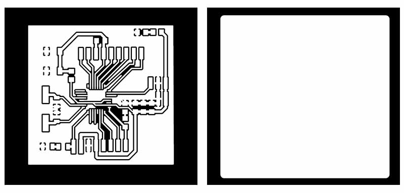
SECOND BOARD: PRODUCTION
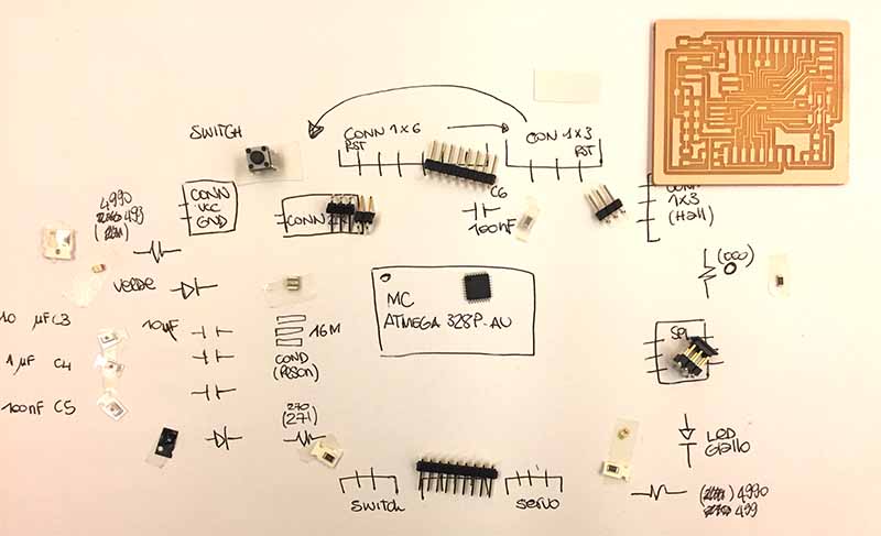
After the milling I have corrected the file that you find below to download
SECOND BOARD: PROGRAMMING (week 12: output)
During my research I found several examples of projects made using servo motors as outputs. This helped me understand but I still do not know what kind of servo motor I need. As soon as the new sheda is ready I will start to do some tests, above all because in the final project it will be necessary to manage the end of the race with precision. Examples and resurce with arduino:
NEW DEBUGGING
Since the card continued to give errors of connection we thought that the microcontroller was damaged, so we changed it
Even after this operation the card does not work, the error was linked to the signature, moreover the micro was heated so we have revised the schematic and milled a new board
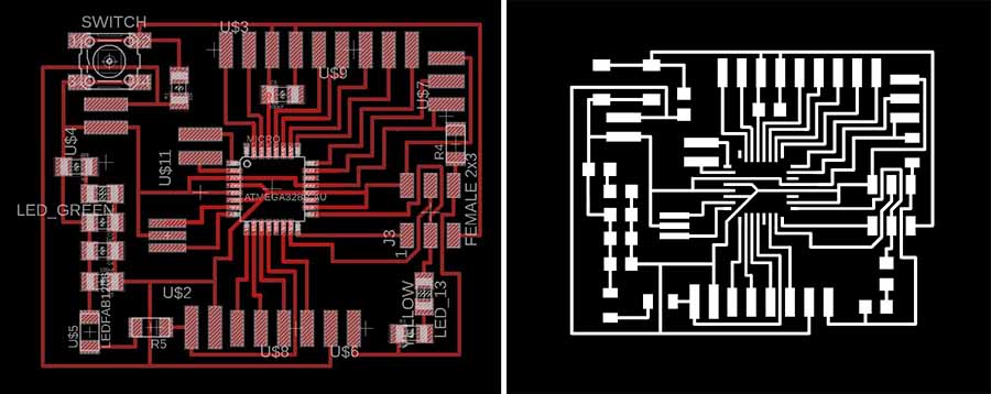
MAIN BOARD VERSION 3: short story of a failure
In the new tab we have modified some components and connection, unfortunately it still does not work.
I also made a reset error during the contour milling, which we managed to solve, but despite this the board never worked.
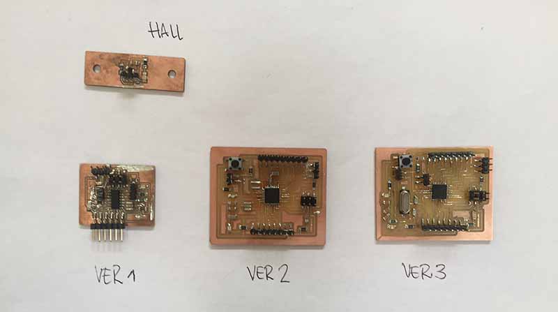
MAIN BOARD VERSION 4: maybe it works
In the new tab we have modified some components and connection, unfortunately it still does not work.
I also made a reset error during the contour milling, which we managed to solve, but despite this the board never worked.
PROGRAMMING
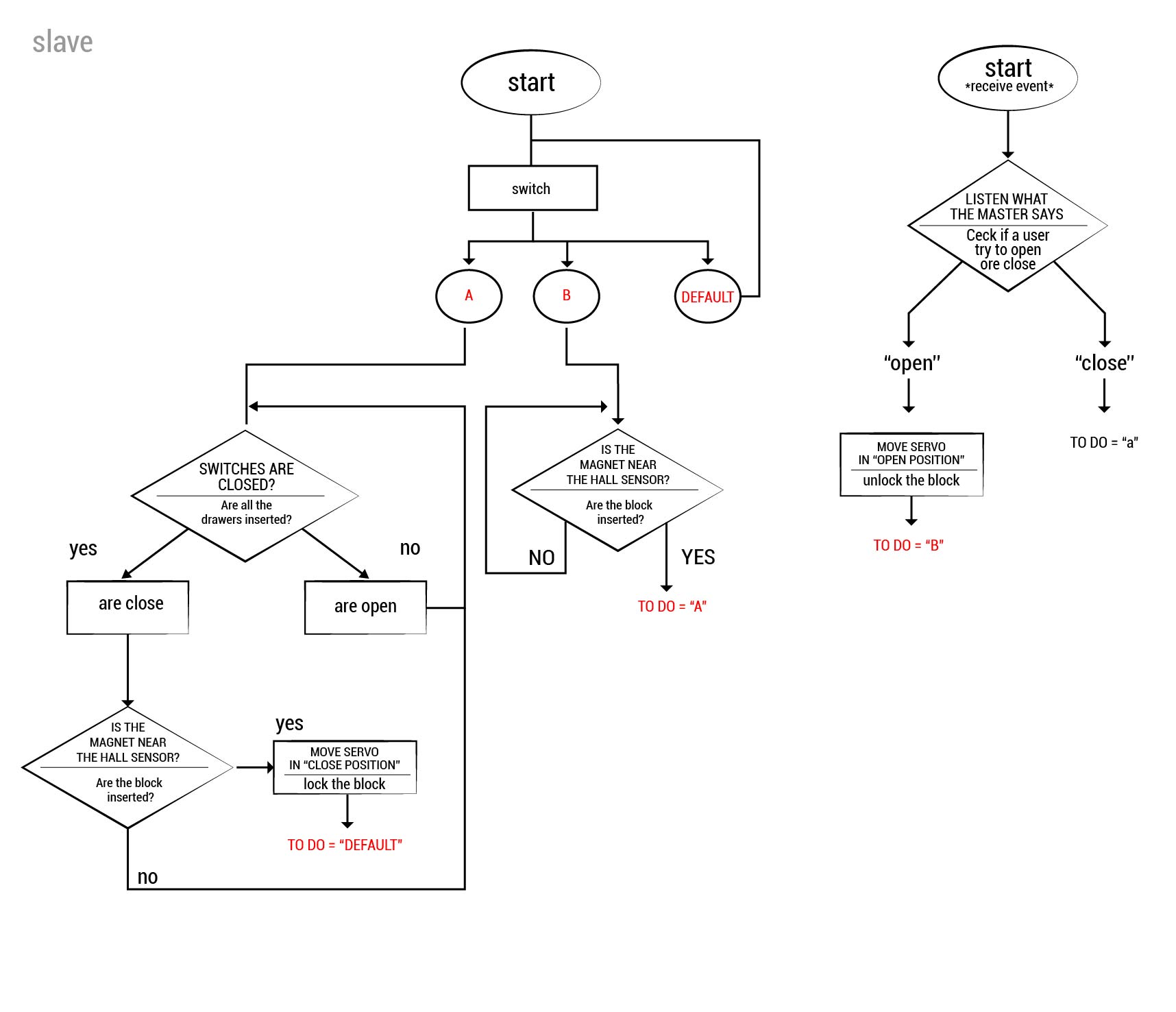
Within my final project the locking system will be managed by 2 "inputs": a digital one (the switches that verify that the drawers are inserted) and an analogue one (hall sensor), under a video of the switches.
testing switch led from lauracip on Vimeo.
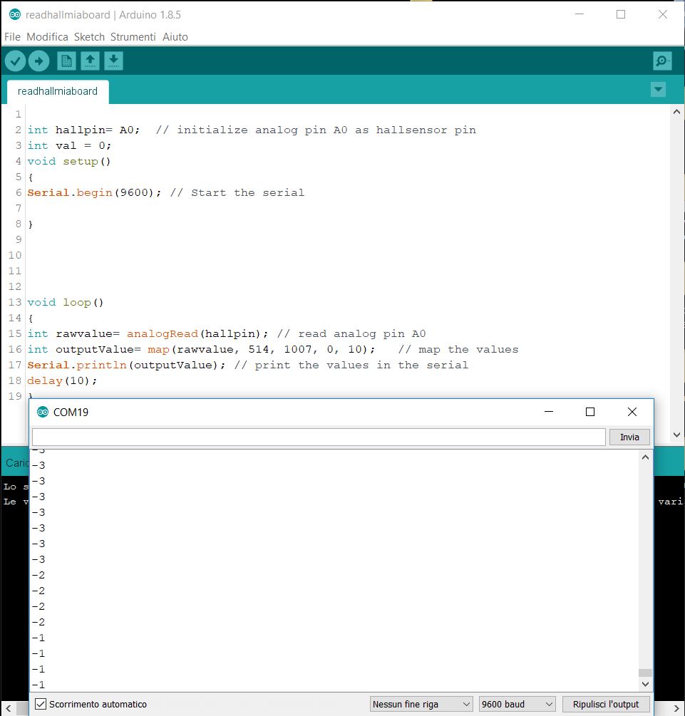
I tried to burn the bootloader with a fairly generic analog read code and modify pin. It works but without a mapping it does not behave well if it works as it should. I try to approach different magnets.
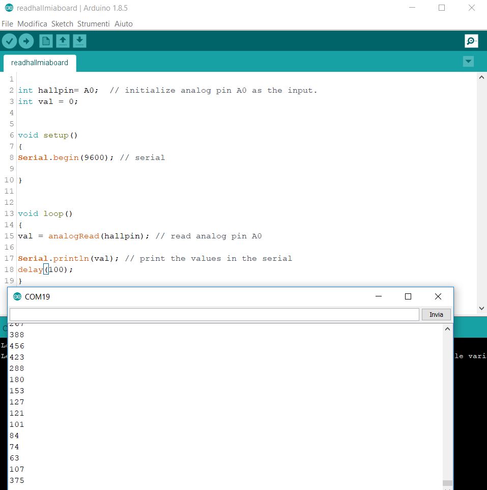
Then I try to insert a map Function.
    int hallpin= A0;  // initialize analog pin A0 as hallsensor pin
    int val = 0;
    void setup()
    {
    Serial.begin(9600); // Start the serial

    }


    void loop()
    {
    int rawvalue= analogRead(hallpin); // read analog pin A0
    int outputValue= map(rawvalue, 514, 1007, 0, 10);   // map the values
    Serial.println(outputValue); // print the values in the serial
    delay(10);
    }
- arduinoplaygroud.
- extra board with hall sensor.
- other.
- instructables.
- allarm.
From this first part of the code I understood that it was necessary to integrate all the other parts for the final project and to write the code of the final project already. According to a precise logic. For which files that already integrate the servo motor.
Examples with arduino:
The in-depth part of this code will be documented in the coming weeks (output, communication, interface) and in the project development page.