Hi, I'm Federica!
This is the online diary of my experience throughout the FABACADEMY 2018 at OpenDot, a FabLab based in Milan, and at FabLab Valsamoggia, the FabLab I'm associated to, in the countryside between Bologna and Modena.
I'm very interested in the role of the design in the educational field, and I've investigated this topic in my Master Thesis suggesting the reuse of an abandoned countryhouse as an alternative learning environment based on experience in local territory and the use of new technologies. I want to keep experimenting on this topic, and I think that Fabacademy will help me in learning new competencies and getting in contact with new realities all around the world.
Here you can find some of my works as a graphic and web designer (and also other projects), and here.I've decided to follow the FABACADEMY because I strongly believe in innovation and DIY culture, and I want to explore different fields and learn to do create ene more objects and stuff. I'm also reflecting about continue on the road of research in design, education and new technologies, and I think that FABACADEMY could be a great opportunity for me to improve my knowledges about the maker movement and new (but also old) technologies. I've started the FABACADEMY 2018 a bit late (at the end of MArch), because I was graduating from the MA.
1 - Project Management
The very first exercise of the Fabacademy 2018 was the initial definition of our final project. We were asked to make initial skecthes of our final project idea, and try to schedule all the steps to arrive at the final prototype.
 The idea
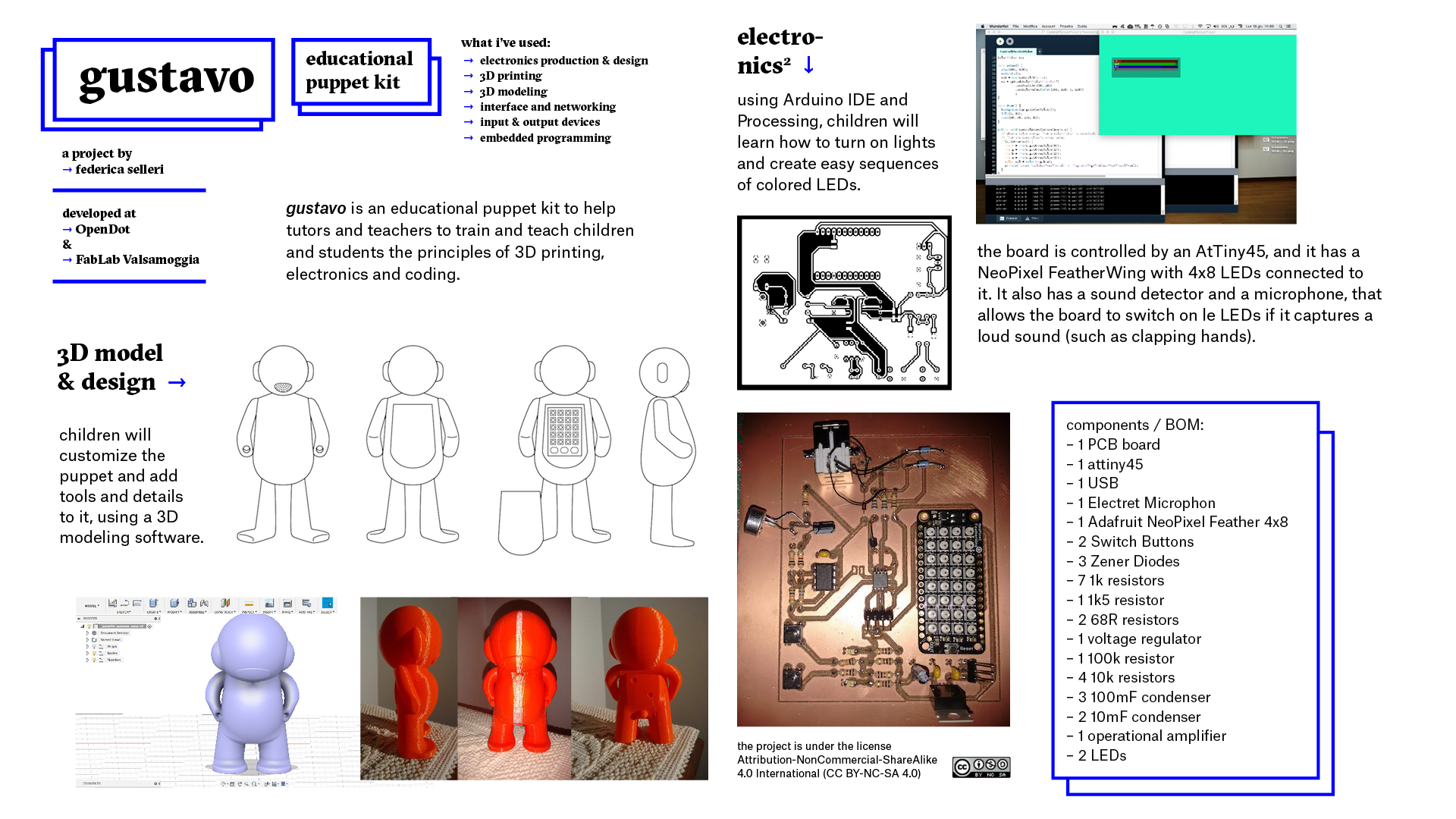
My idea is to create an educational tool that can be used in schools to help teachers and tutors to teach 3D modeling and programming in a simple way. I was thinking about the shape of this tool, because there are already a lot of products designed for this purpose. But most of them are just pre-designed complete kit that children and youngs have to build following instructions.
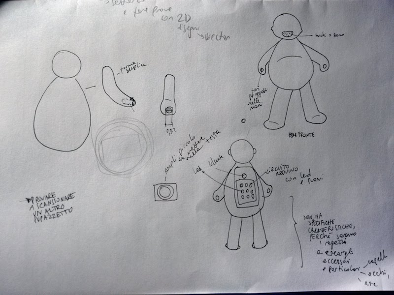
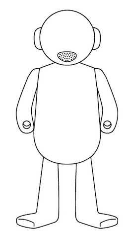
So I've tried to sketch a first rough draft of my idea, which consists in a blank physical character printed in 3D with an Arduino board inside, with LEDs and a small loudspeaker for playing MP3s.
Background
I've decided to focus on this idea of a blank character that can be customized, because within the FabLab Valsamoggia we are establishing a collaboration with primary and secondary schools and their teachers. We're organizing some laboratories for children about 3D modeling and programming and I'm the tutor who is organizing them. So I've thought that this object could be a helpful and precious resource for these laboratories. It could also be a good way to bring outside what is designed and produced during this journey.
First sketches
I've used paper and pencil to put my ideas into concrete, and I've tried to define the shape of the character.
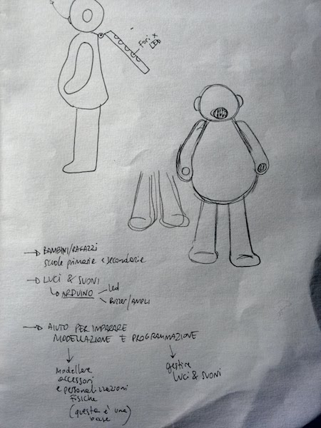
It should be as basic as possible, to let children and other possible users to customize it, adding details and even accessories.
I've decided to create a sort of hole in the hands that can be used to insert things in it. Users can think of objects or other tools that can be part of the customization. You can follow the development of the final project here.
Personal website
Then, as second part of this assignment, we had to create our personal website where we're going to publish our works and to tell our journey to other participants of the Fabacademy, sharing our results and progresses.
In my previous university course I've learned how to code with HTML and CSS, and some basic knowledges of Javascript. So I've had already a code editor app installed on my computer, which is Sublime Text. It's a free and cross-platform app and it has a wide range of packages taht you can use to customize the interface and to make easier code editing or generation. You can download it from here.
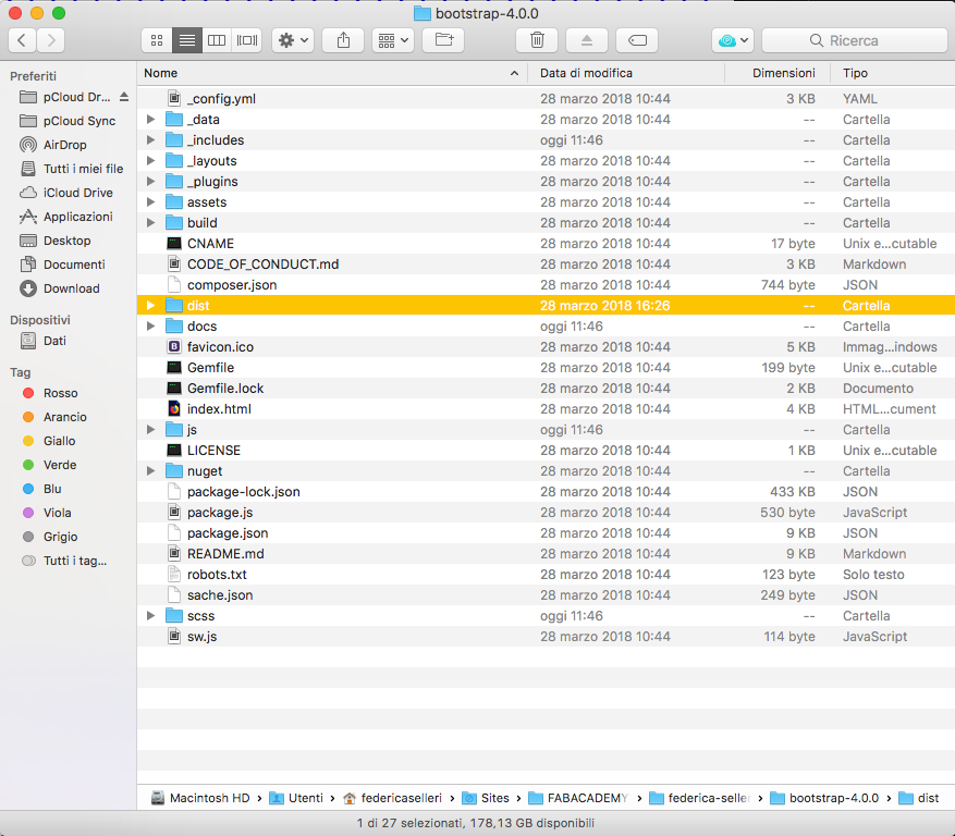
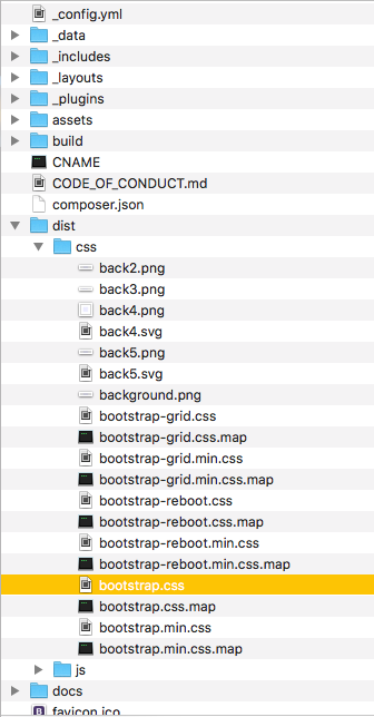
Firstly, I've downloaded the Bootstrap folder from the website, and put it into the git folder in my local repository. Bootstrap is a open-source toolkit for the design of websites and apps. It has a huge front-end components library that you can both use as it is or edit completely according to your needs. It's mainly used for developing with HTML, CSS, and JS. I've un-zipped the folder and this is how it looks like:
Then I've created a new file, called 'index.html', and selected the language I was about to use (in this case it's HTML).
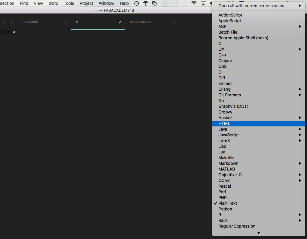
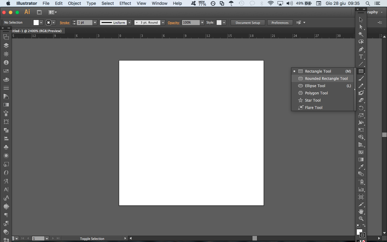
So I've started to develop the index page. When you start to design a website, there's a specific sequence you must write to start designing your website, and it's the following. You can simply tap a "d" and choose the option called "doctype", as you can see in the image:
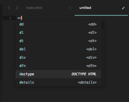
This is what is going to appear after you select that option:
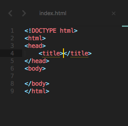
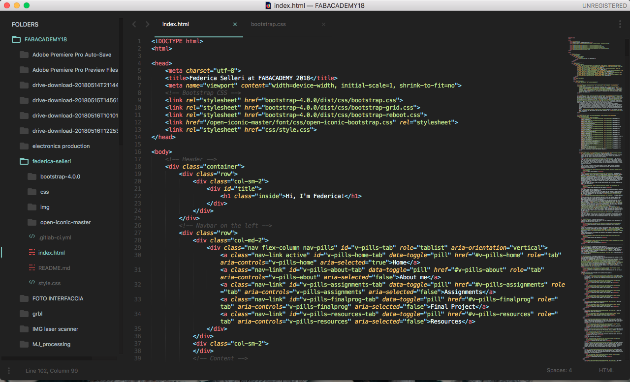
I've chosen to use a single page in .html and a Bootstrap component that allowed me to create dynamic tabs you can navigate through. There is a navigation bar on the left of the website, and if you choose "assignments" you'll see the list of the vairous exercises. If you click on one of them, you'll stay on the same page but positioned under the selected exercise.
Setting of Git Repository
To put my website online I've set a Git repository connected to the Fabacademy general repository on Gitlab. I didn't need to download Git because I've had already installed it, so I've simply had to connect the local Fabacademy folder to the remote repository.
First of all, I've needed to connect Git to my local folder with all the material of the Fabacademy. I've needed to go with a cd into the fabacademy directory, and run git init. In this way the folder is connected with git.
Then I've needed to clone the remote repository on my page on Academany and run git clone https://gitlab.fabcloud.org/academany/fabacademy/2018/labs/fablabopendot/students/federica-selleri. In this way I've generated a local copy of the remote repository.
I've put all the website files on this local repository, and then run git status to verify the status of the files, which are uploaded or not.
When there's something to be updated, it appears in the terminal as a red line. So you can add each modification to the remote repository by running git add and write the file name I want to update. You can also decide to add each new file, and write git add .
To validate modifcations you need to write git commit -m "here you can write a message to explain the modifications", after the git add. Now the file isn't in the remote repository yet: you need to write git push and the name of the remote respository, which in this case is origin.
To update the local repository with the latest commit you need to run git pull and the name of remote repo. There are several tutorials available online, if you need to know more commands: the official Git reference guide, Git, portable guide, Visual Studio guide.
2 - Computer Aided Design
During this week assignment we were asked to try many different 2D and 3D softwares to sketch our idea for the final project.
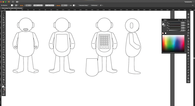
I've used my sketches as a basis to create a more defined shape of the character. I've started to do the 2D drawing with two different software, Adobe Illustrator and GIMP.
With Adobe Illustrator I've created the outline of the character, using vector drawing to create clean shapes.
You can download the SVG sketch here.
To model my character in 3D, I've decided to use Fusion 360, a software for parametric 3D modeling. The license if free for students and educators for three years. I've never modeled anything, so it has been quite hard to approach to a product like Fusion. Before becoming too desperate, I've decided to start from another software, easier than Fusion. It's a free online 3D modeling software that is currently used in schools to teach pupils about 3D world, and it's called Tinkercad.
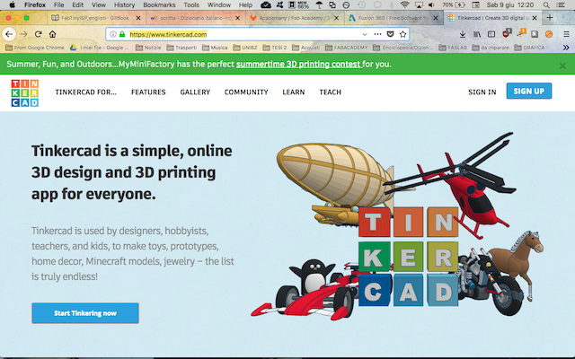
You just have to sign up with an e-mail and a password and you can start immediately to model.

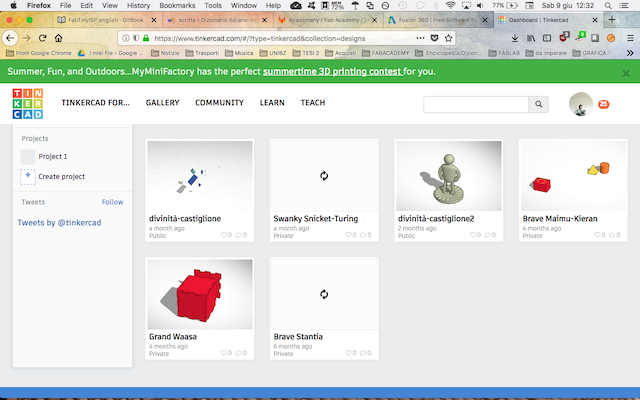
This is what you see when you open the app after the registration.
It's similar to most of the other 3D softwares: you have the navigation cube on top left, and some options on the top bar.
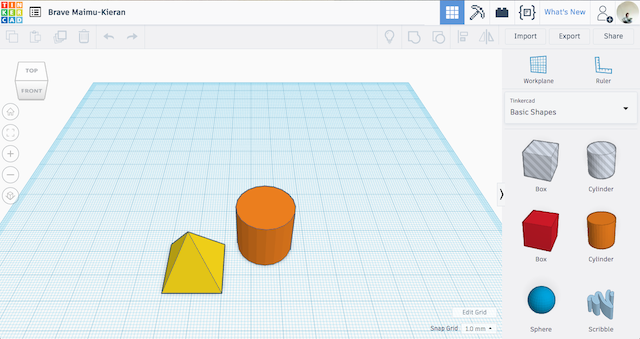
But Tinkercad works in a slightly different way from the others: you can't create a skecth directly on the workplane, you have to start from 3D volumes, such as cubes, pyramids, cylinder, and so on.

I've used Tinkercad to design a initial sketch of the puppet:


With Tinkecad you can create simple sketches, but for my final project I needed something more professional.
The final version is designed on Fusion 360, an Autodesk software for modeling. I've started also here with volumes as bodies:


I've added the legs, using two other cylinders.

I've decided to design the head bigger, to make the puppet cutier and funnier.

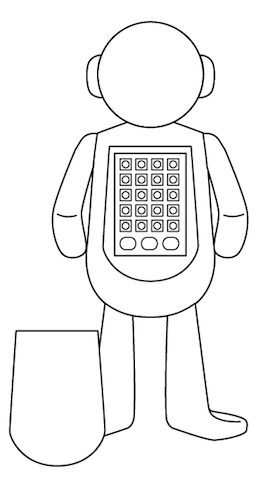
After a first trial, I've decided to put a case for future boards in the back of the puppet: in this way, you can place different boards in the case, and even close it.


Here you can download the STEP file and the edition file of the puppet.
3 - Computer-Controlled Cutting
For this individual assignment the goal was to learn how to set a laser cutter, and try to cutter something I've designed. I've also have to try to cut something using the vynil. You can also check the group assignment here.
Laser Cutting
The assignment for this topic was to create a press-fit construction kit. I've decided to create a dice, in a way that you can regulate the thickness of sides and joints. The six pieces of the dice are three couples of identical pieces. It's impossible to make six identical pieces, because you need opposite joints to be connected. I've started on Adobe Illustrator to create the six sides, then I've exported it as .svg, a file extension that can be read as a sketch. I've imported the sketch in SolidWorks:

I've added the quotes to the sketch, because in this way you can add variables to each paths.

I've extruded the external shape of 4 mm.

I've connected the quote to the value,

and then I've selected the name of the variable associated to the value.

And the variable has been accepted.

Then I've to define the other quotes related to the same variable, in order to allow the change of all the quotes related to the same parameter:


In this way you can simbply change the size of the joints according to the material you want to use. When I've defined all the quotes, the side looked like that:

After that, I've tested the parametric level of the dice: I've tried to modify the thickness from 4 mm to 7 mm.


15 video parametrico from federicaselleri on Vimeo.
So the parametric quotes change according to the value of the thickness you want to apply. I've had to export the file as a 2D in CorelDraw, in order to generate a suitable file for the lasercutter.


After that, I've generated a .dxf file by exporting the file. Then I've saved the file on a USB stick and copied that into the PC connected with the Laser Cutter.


I've opened the Laser cutter software, which is Lasecut Engrave, and imported the .dxf file.


And it appears your drawing.

You have to move it according to the space on the panel you want to cut on, so in my case I don't have space in the center, and I've moved it on the top. To do so, you have to click on the drawing to make red lines and yellow squares appears, and then you can move the drawing by simply dragging it on the workspace.


On the right of the workspace, there's a column with the cut and/or engrave settings: I've needed both, because I wanted to cut the six pieces and to engrave the dots. It's initially set with two cut layers, and I've defined one of them as "Engrave". I've left Cut settings as they were.

I've set Engrave settings in this way:

The colors of the paths help you to recognize which layer is related to each paths. In this case, the blue one is related to Cut, the black one to Engrave.


After that I've needed to calibrate the laser: I've measured the distance from the wooden panel to the bit, to check if it was the same on the entire surface and avoid mistakes.

Then I've connected the Laser cutter to the software by clicking in bottom right the name of the Laser cutter available and inserting the USB cable in the PC, and then pressed "Download". In this way the file is going directly in the machine via USB.

Another important action is to run "Test" on the machine, to check if it has enough space for the cutting.


If everything is ok with the test, you can press "Run", and the machine starts to work.


And here's my final object!

You can download the SVG files here and the SolidWorks file here.
Vynil Cutting
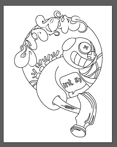
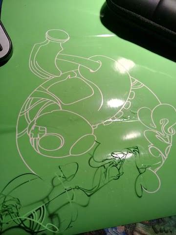
For the vynil cutting, I've decided to create a sort of a logo for the character, in order to assign it an identity. As usual, I've started from sketches on paper.
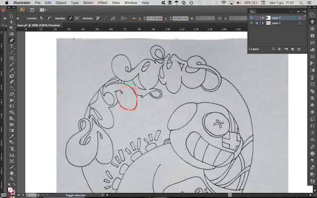
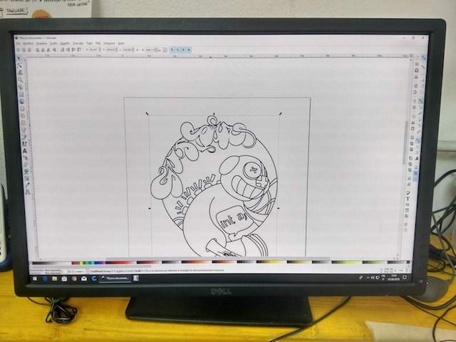
Then I've taken a photo and uploaded it on my computer, and imported in Adobe Illustrator. I've redrawn it as a vector image, in order to be read by the laser software.
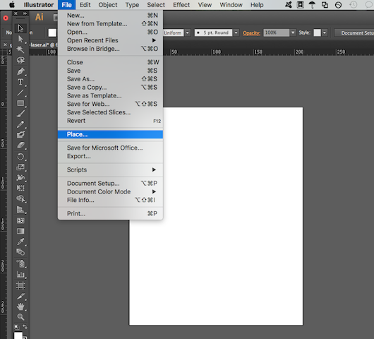
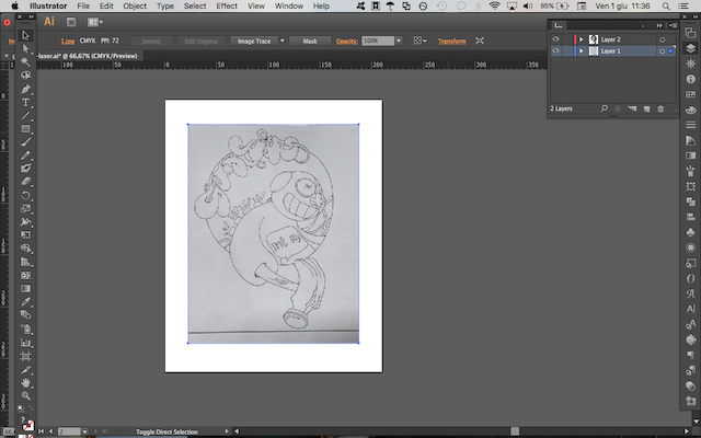
Firstly, I've put the image in the blue layer and blocked it. Then I've created another layer (the red one) in the same file, and I've retraced each line with the tool "Pen", available on the left palette of tools.
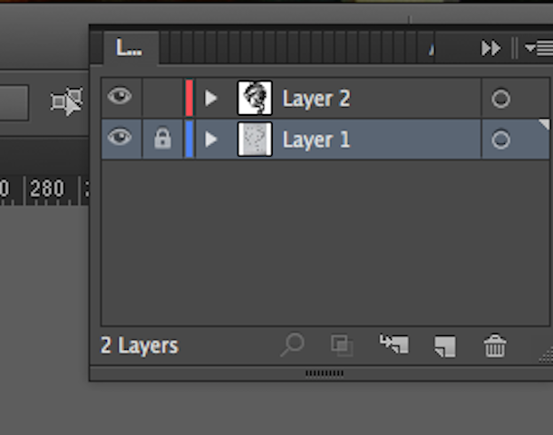
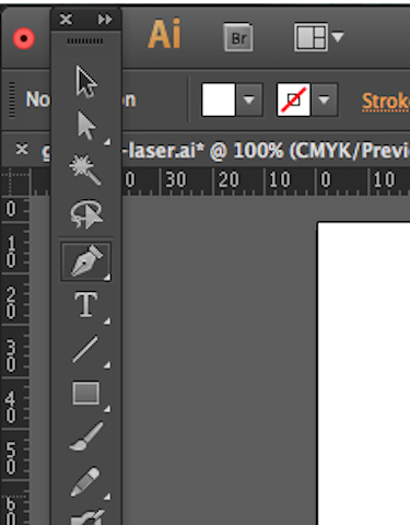
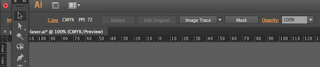
[There is also another option to retrace automatically an image in Illustrator, and it is called "Image Trace". You can find it in the top bar of the interface when you import an image. I prefer not to use it because it is not so much precise, but it depends on the result you want to achieve.]
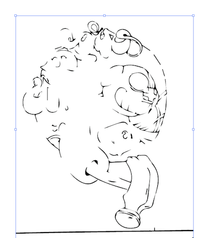
I've also tried to improve some parts that didn't convinced me so much. The last operation you have to do when you're fine with the drawing is the expand of the paths, to have the outline of each line and not the single line. This is important because the vynil cutter usually follows each line, and if you want to have visible lines and boundaries you need to expand the strokes.
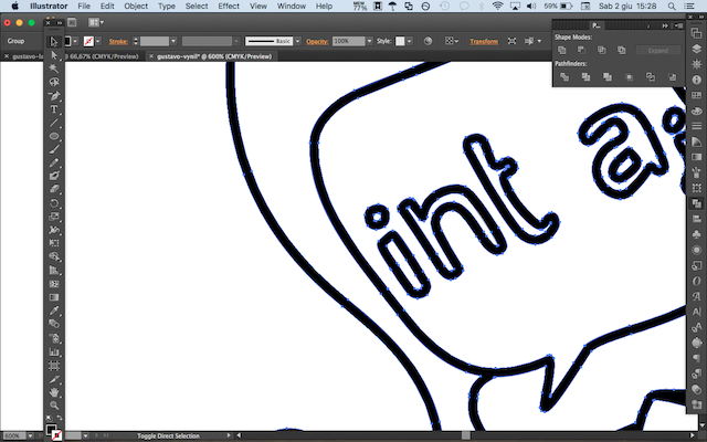
When I finished the retracing operation, I've decided to manipulate a bit the paths of the name "Gustavo" in the top part of the image.
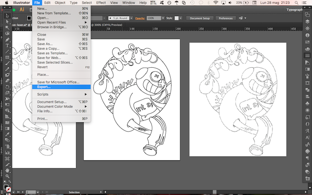
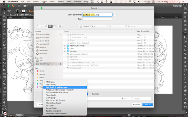
When I became satisfied with the result, I've exported the board with the drawing as .dxf (AutoCAD), because it's the format that vynil cutter reads better. I've saved the file on a USB stick.
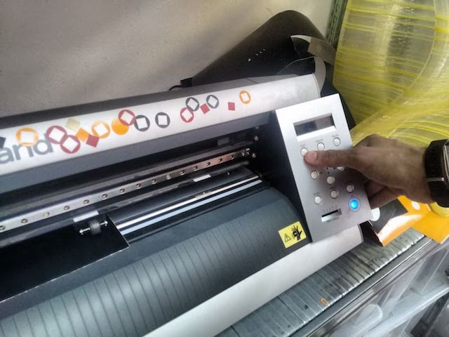
Before cutting, you have to place the material you want to use in the machine: I've choosen black vynil, and picked up the roll and inserted into the split. It's important to set the two small wheels under the white signs, and your material must be in the middle of them.
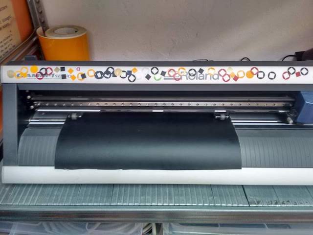
Then you can turn on the machine and run the test, to check if everything works fine.

vynil1 from federicaselleri on Vimeo.
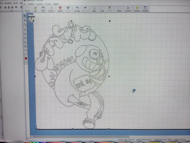
If the test worked, you're ready to start. I've openend the PC connected to the Vynil cutter at OpenDot, and opened Inkscape, a free and open-source software for vector drawing. Here I've imported the file, and enlarge a bit the image because it was a bit stretched.
Then under "Extensions" I've chosen "Open in CutStudio", to create the file for the machine.
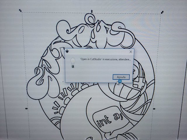
The image will look in this way: you will see the paths and the placement of the drawing in the stock.
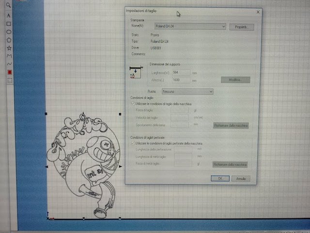
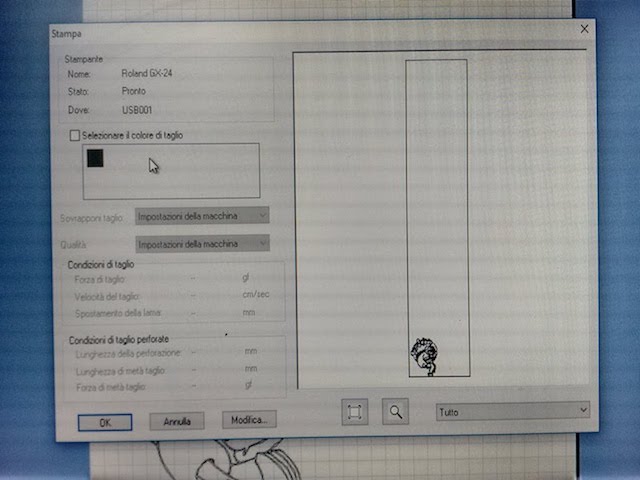
After you set the image on the stock, you can choose File > Cut Settings from the top bar, and select the machine (in this case it's a Roland GX-24). CutStudio detects automatically the dimension of the support, but it's always important to check if length and height are correct.
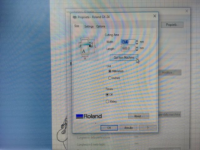
To check dimensions you can choose "Properties" next to the name of the machine, and select the option "Get from the machine", and then press ok.
Now we need to send the file to the machine, and we select "Cut" from the top bar.
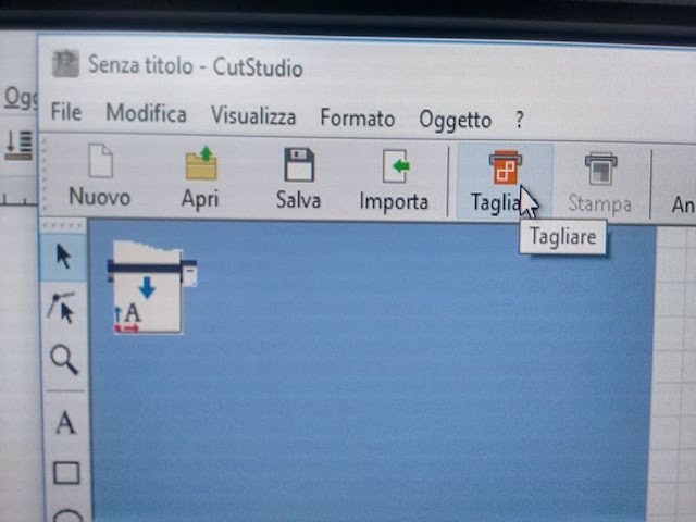
This is the last check of the file, you'll see the position of the image in the stock and the status of the machine. You don't have to press anything except OK, but always check if everything is fine.
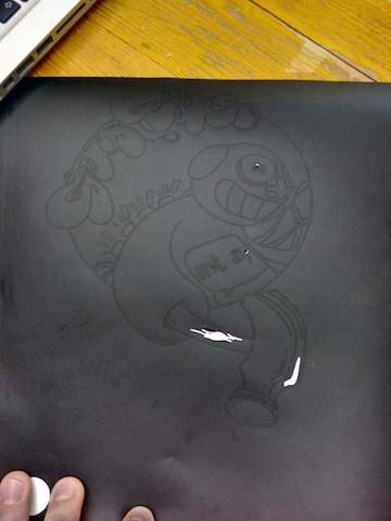
Then the machine starts to work:
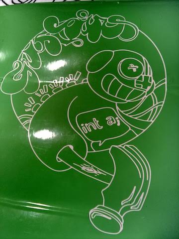
When it has finished, you can remove the vynil by pressing a lever on the left of the machine and cut your image. At this point I've to decide what parts of material I want to remove, and I've decided for the fills.
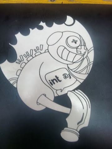
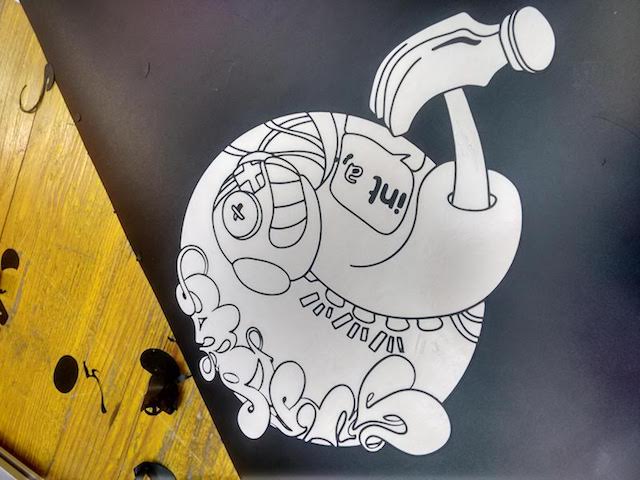
I've also made another trial with acid green vynil, but this time I've decided to leave the fills and take out the strokes.
You can download the SVG file here and the DXF file here.
4 - Electronics Production
The individual assignment consisted in the setting of the milling machine and the milling of a PCB board, and then the programming of the circuit. You can also check the group assignment here.
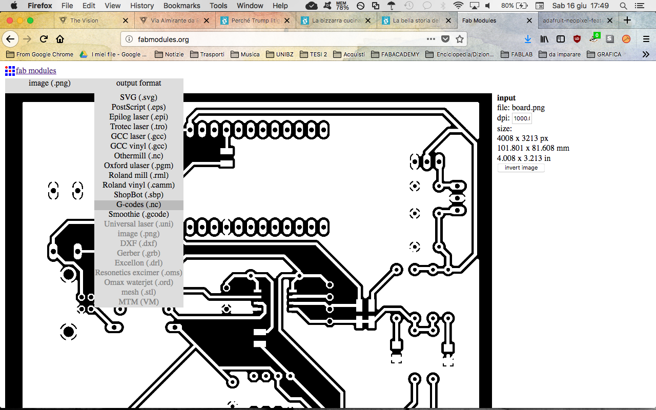
Firstly, I've downloaded the example of a circuit from the official Fabacademy tutorial: the internal traces and the external cut. The two files are basically PNG images, and we had to convert them in suitable files for the milling machine. Using Fab modules we managed the settings of the milling machine in the most precise way.
Here's the process I've followed and the settings I've used:
-
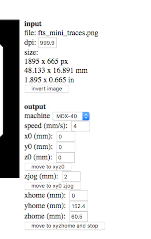
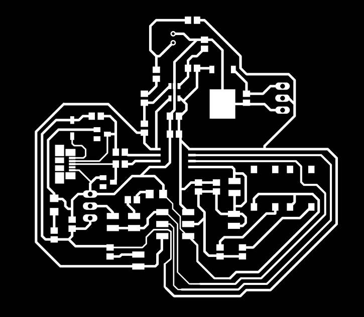
First, I've to upload on Fab modules the .png image I've downloaded previously (the one with just the traces).
Upload of traces image of the circuit in PNG. 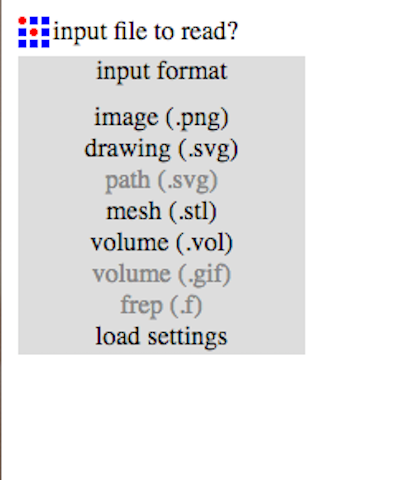
Upload of traces image of the circuit in PNG. 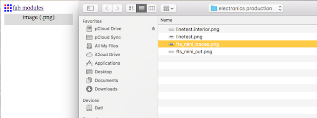
Upload of traces image of the circuit in PNG. 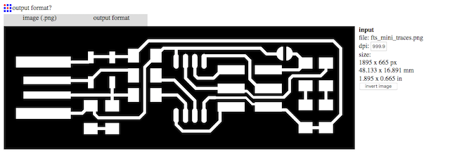
Upload of traces image of the circuit in PNG. -
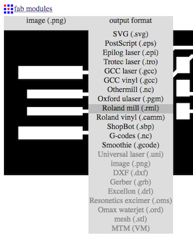
Then I've defined the type of output file I need.
Upload of traces image of the circuit in PNG. -
After the output, I've chosen the process.
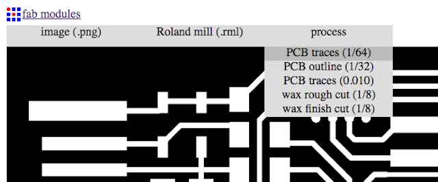
The chosen process is PCB traces 1/64. -
Then I've needed to define milling parameters, in order to get proper settings for my output. Firstly, I've defined the parameters that specify the position of the burin (the engraving tool in the milling machine).
You should be very careful while setting parameters, and you'll probably have to do several trials. Then I've set the parameters about the engraving tool I've decided to use, which is this one: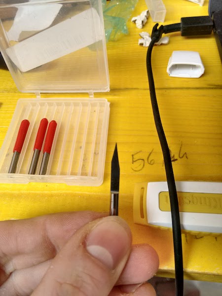
This is a 0.4 burin, I've discovered almost by chance that it was excellent for this work. And the parameters I've used:
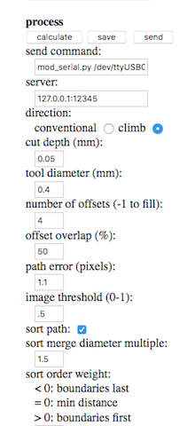
Settings fot the chosen burin. Be extremely careful in defining the depth parameter and the tool diameter. With the bulin you can't be so much sure about the dimension, so I've used a calipers to measure the diameter (the results was 2 millimeters, but with a burin you have to consider a larger size. I've set up 0.4 as tool diameter, and 0.05 as cut depth. -
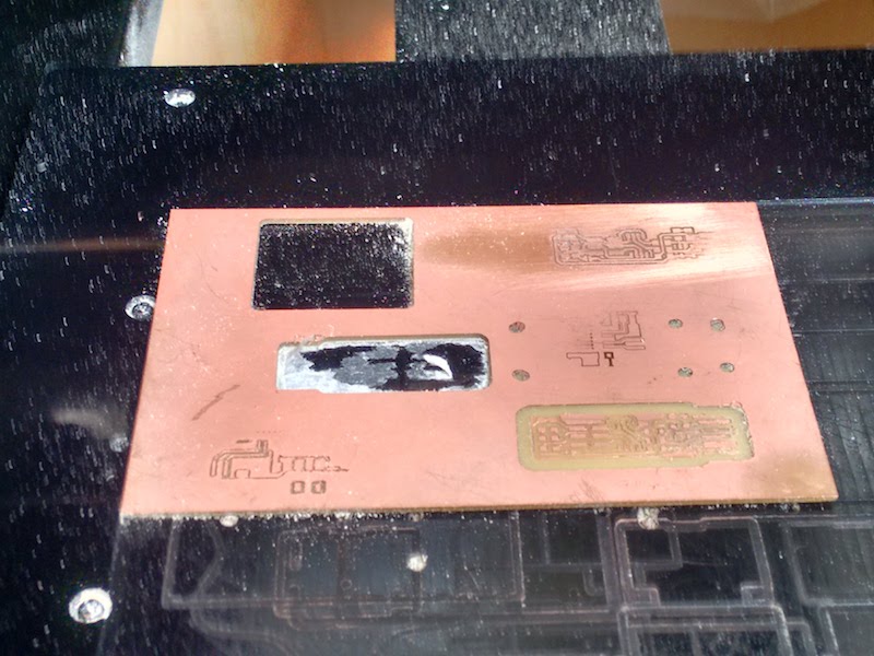
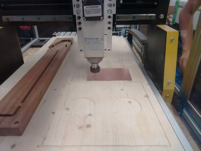
After that, I've generated the .rml file needed for the milling machine. Then I took a PCB to use for my very first trial. I've used double-sided tape to attach the board on the plate inside the milling machine.
Double-sided tape under the PCB -
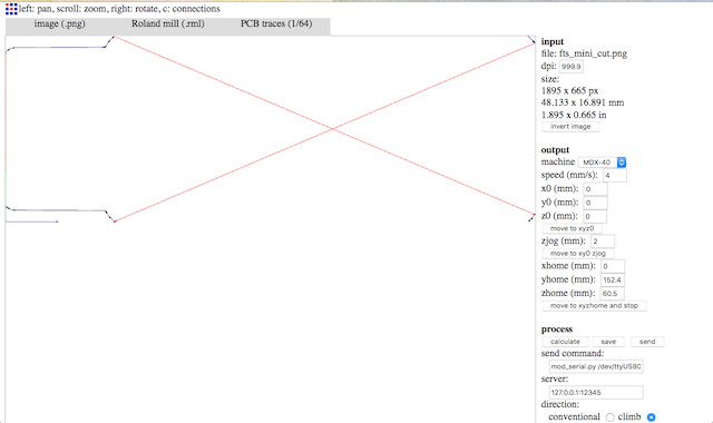
The second step was uploading the .rml file generated on Fab modules in the VPanel software connected with the milling machine.
The interface of VPanel software. In the VPanel software, you have to define the origin point where the milling will start. By moving manually the X and Y axes you can choose the position on the PCB where the milling will start.
Setting the position of engraving tool I've had also to define the third axis, Z, which defines the height of the cutting. This is a quite dangerous action, because you have to pay attention when the tip touches the PCB. Tips are fragile and if you press them too hard against the PCB (sometimes it happens while setting the origin of the axes X,Y,Z) they will break. I've also set the speed to 15000.
-
After the setting phase, I've press the button "Cut" to upload the file in the VPanel. I've imported the file into the software, and then pressed "Output". This will turn on the milling machine, which will start to mill.
Milling machine in action. 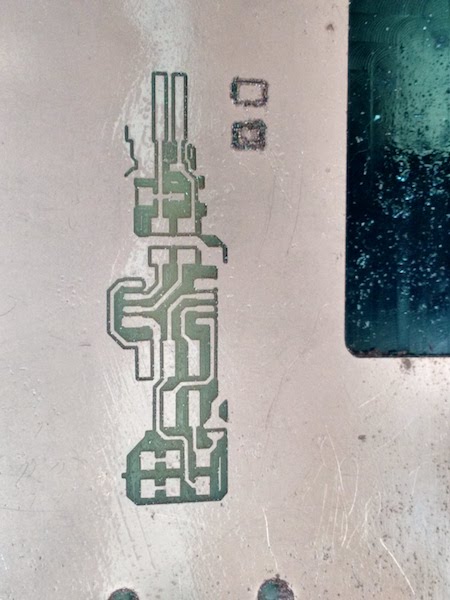
-
When it has finished the traces, it needed the cutted part. To do it, I've prepared previously another .rml file with just the white area that will be cut out.
Then I've uploaded also the .png file of the outline on Fab modules, and selected "Roland Mill" again, but "PCB outline" instead of traces.
In the settings area on the right, I've inserted 0 in x,y,z origin, left the speed at 4, and set 0.6 as "cut depth", 2 as "tool diameter" and 1 as "offset" (we don't need any offset, because it has just to cut).
So I've left the milled PCB in the machine, and upload the new file after changed the tip with a 2 diameter one.
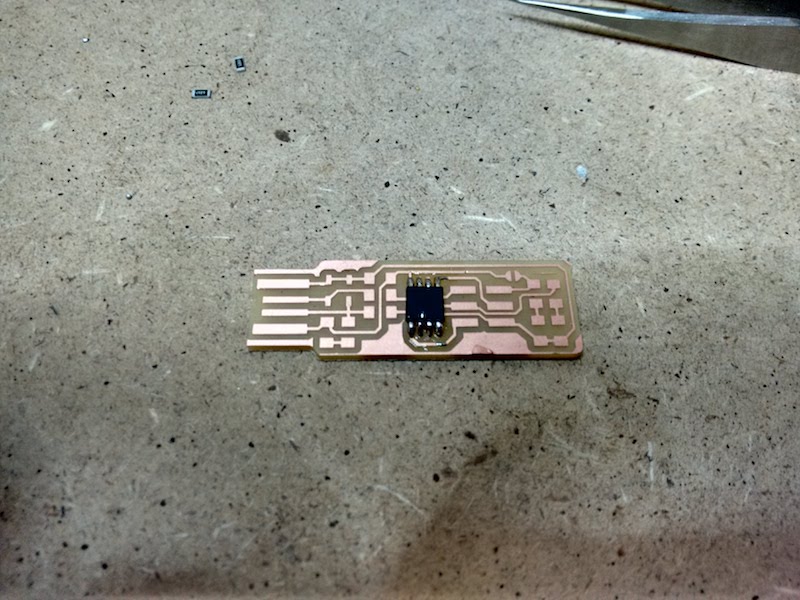
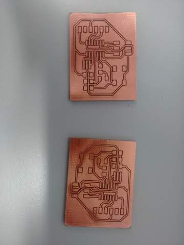
The milling machine started to cut, perfectly around the traces. The result is satisfying: traces are perfectly visible, and I've just to remove some extra parts of copper.
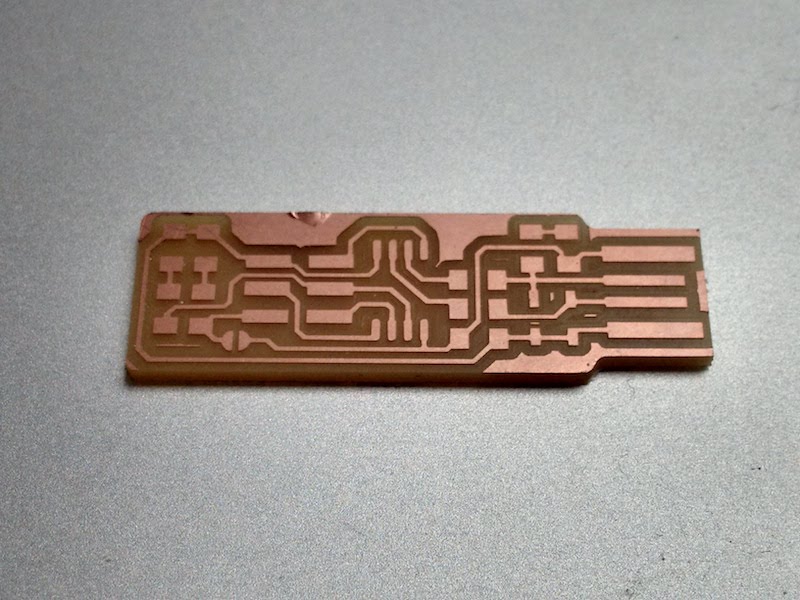
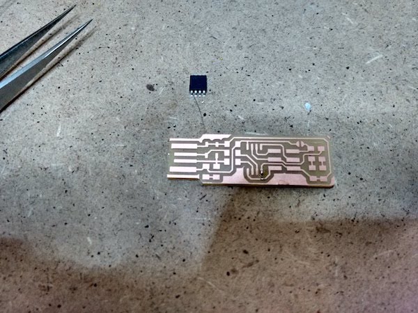
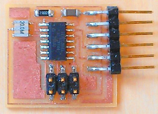
Milling machine in action. After the milling, it was time to solder. I've taken all the necessary components:
- 1x ATtiny45;
- 2x 1kΩ resistors;
- 2x 499Ω resistors;
- 2x 49Ω resistors;
- 2x 3.3v zener diodes;
- 1x red LED;
- 1x green LED;
- 1x 100nF capacitor;
- 1x 2x3 pin header;
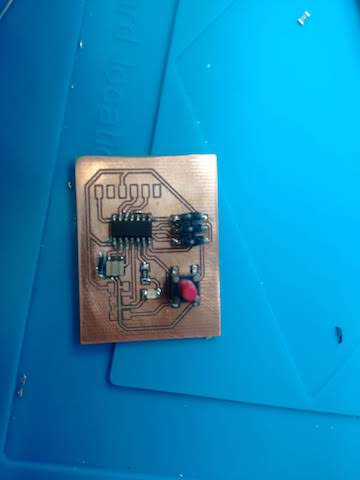
It was my first time with the soldering iron, but after the first moments of hesitation, I've enjoyed to do that. I've started to solder from the most difficult component, the Attiny45, and then the others.
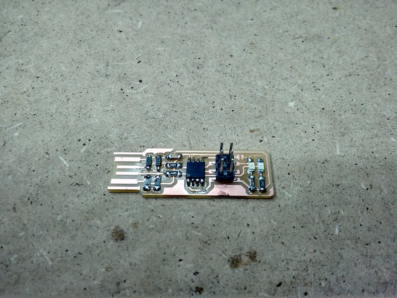
I've also soldered the USB traces to guarantee a better contact during the plugging. Also I've had to solder a bridge in the J1 position, needed to join two traces for the programming moment, and then remove it.
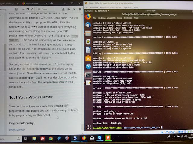
After the soldering I've started to prepare for the next phase, programming. I've followed this tutorial from the official Fabacademy website.
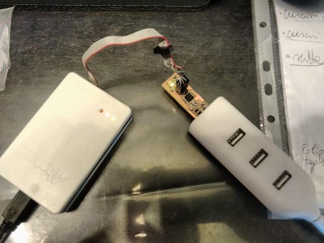
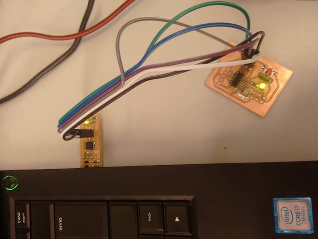
I've decided to use a specific programmer, the Atmel ICE.
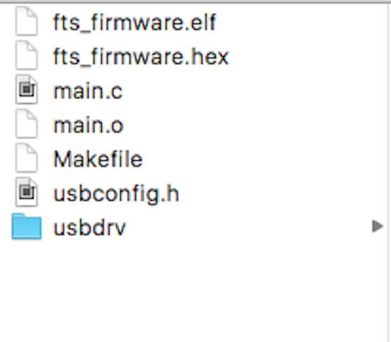
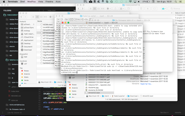
Initially I've tried to use my MacBook to program it, because there was the possibility to use CrossPack, a sort of installer for programmers. After the installation, I've downloaded the firmware source code and extract the zip file in the same directory of all the other fabacademy files. Then I've launched the terminal and within the same folder of the firmware I've launched make. With this commad I've generated the .hex file that will be programmed into the Attiny45.

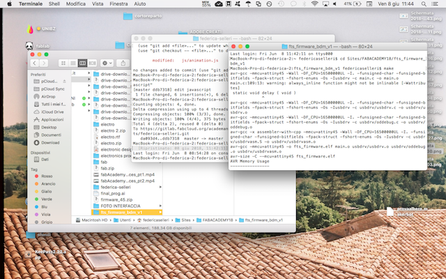

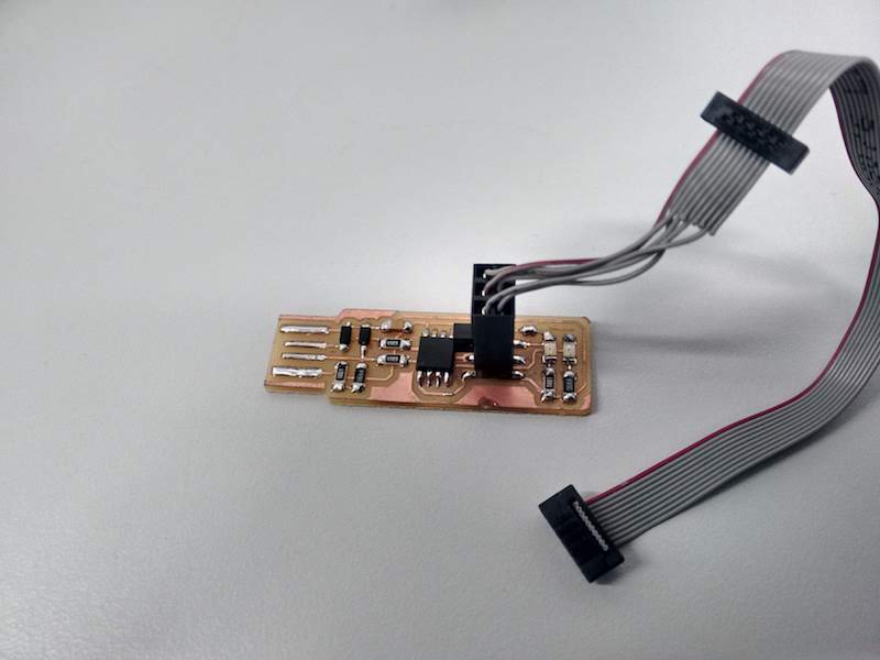
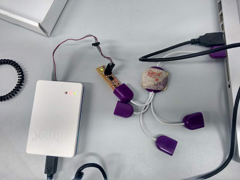
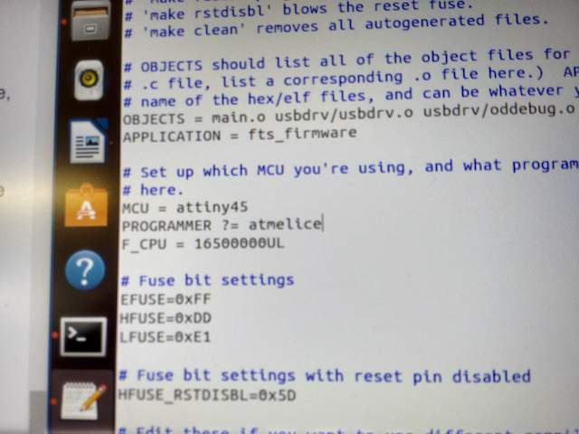
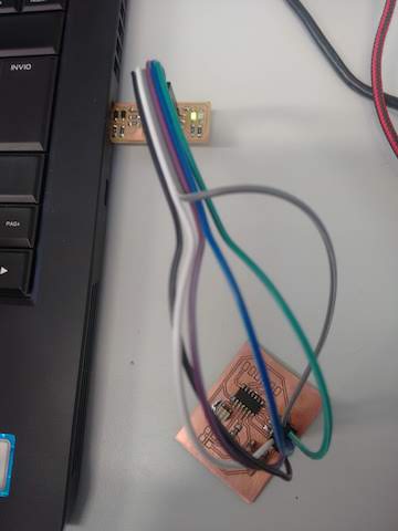
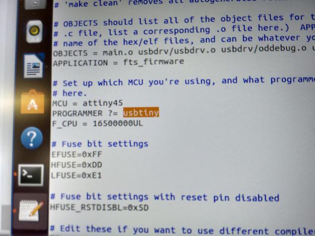
Everything worked fine. I've then opened the .makefile and changed the type of programmer I was using: where there was "usbtiny" I wrote "atmelice". I've used Sublime Text to edit the Makefile. After that I've plugged the USB side on a USB cable, and place the installer port of the Atmel ICE on the ISP header.
As soon as I've plugged the cable, the LED lighted up. In this moment I've discovered I've switched the red and green led, so the green LED lighted up.
When you connect the programmer to the ISP header you should be careful to connect the header with the 1 with the correct hole in the programmer, and you can find it because it has usually a sign on it.
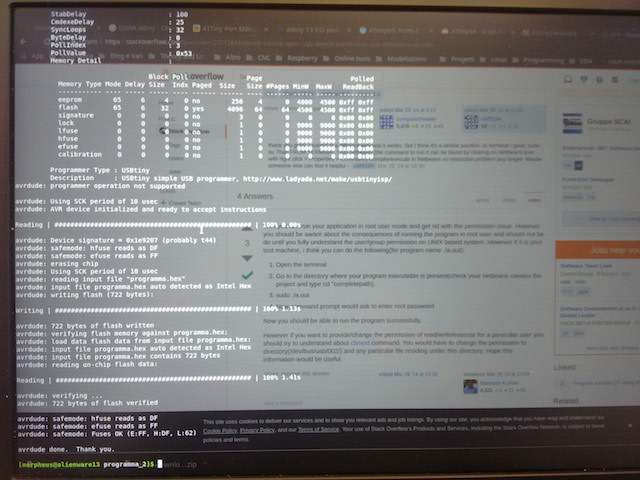
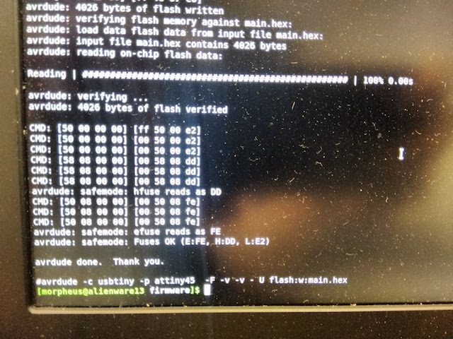
I've opened the terminal again and run make flash. It was supposed to use the .hex file to program the chip, but something was wrong. The result was that I didn't have the permissions to do it.
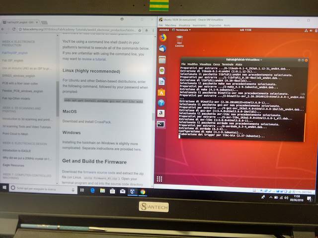
I've started to watch some tutorials, available here and here. I've found out that the problem was that MacOs Sierra has improved the security settings in a way in which it's more difficult to access advanced settings. After three hours of trials, and none solution, I've decided to try to use Linux, which was "highly recommended".
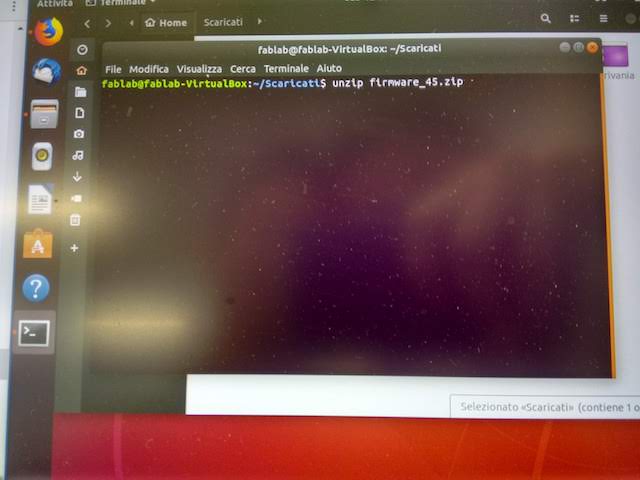
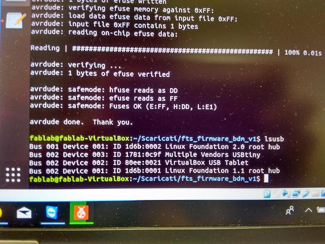
I've used the PC in the FabLab Valsamoggia with Ubuntu installed in a virtual box. I've repeated the same workflow from the very beginning: instead of installing other programs, I've had to write a line in the terminal (sudo apt-get install avrdude gcc-avr avr-libc make) to run avrdude. I've downloaded again the firmware source code and run make. This successfully created the .hex file, and I've also edited the Makefile in the same way as before. I've plug the board into a USB port, and connect the ISP header to the Atmel ICE.
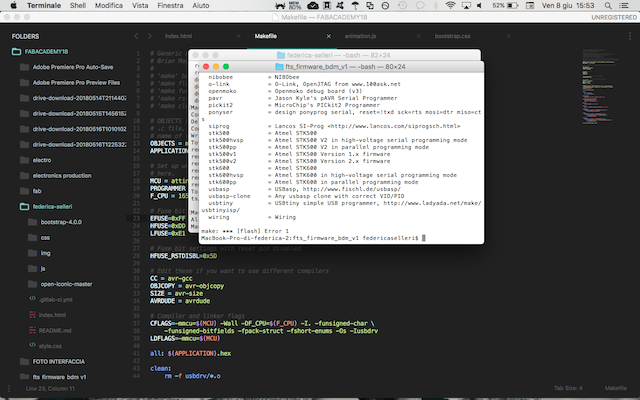
In the terminal I've run make flash, and something was wrong again. This time the error was different:

I'm not so used to Linux environment, so I've needed a bit of help from my FabLab mates. Two of them explained me how Linux works and what kind of error was that.
After some hours of trying, we tried to force the process and it finally worked!
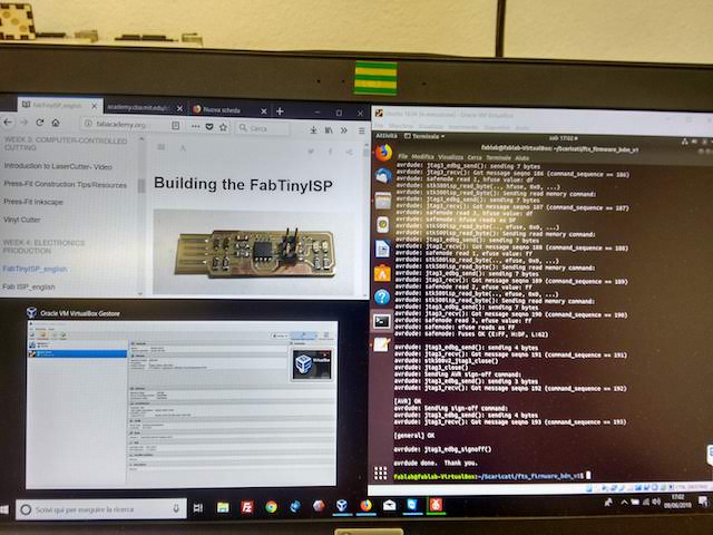
At this point I've had to set the fuses:
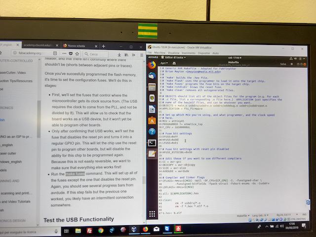
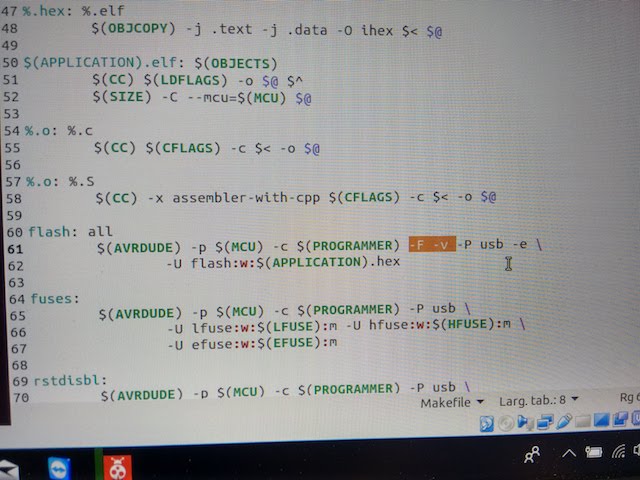
We'had to force a bit some passages (using , but after some hours trying the PC recognizes the FabISP as a USB!
You can download here the folder with the edited Makefile and the firmware.
5 – 3D Printing and Scanning
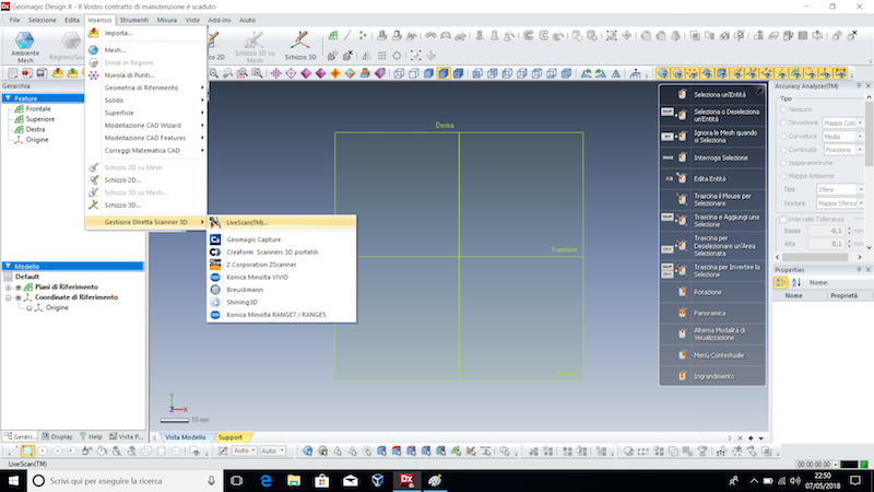
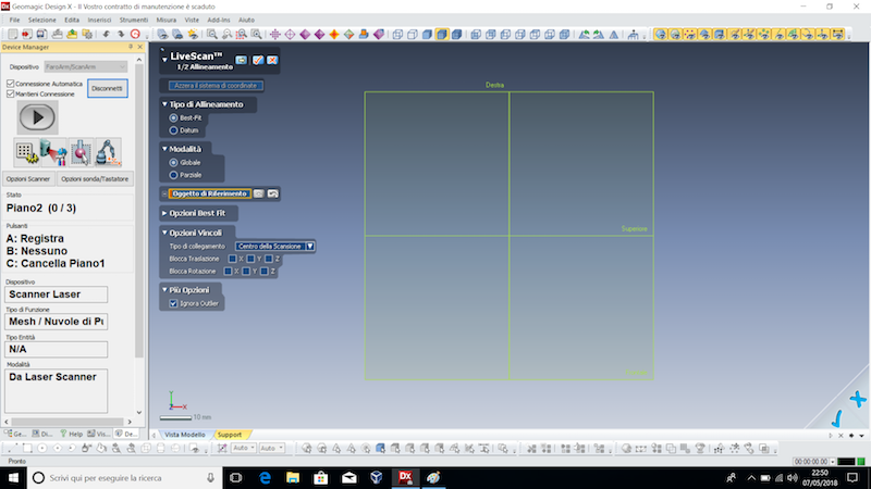
3D Scanning
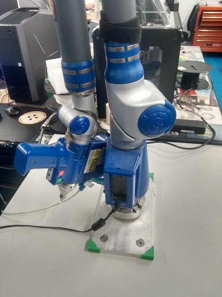
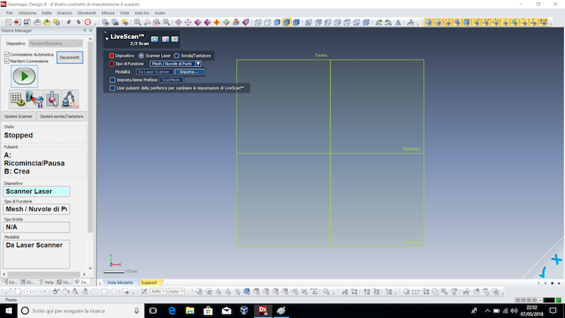
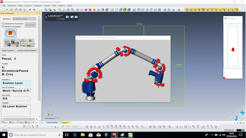
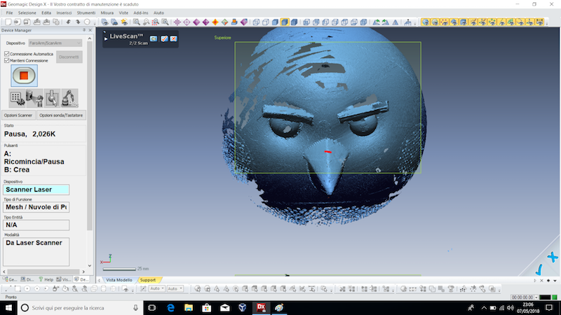
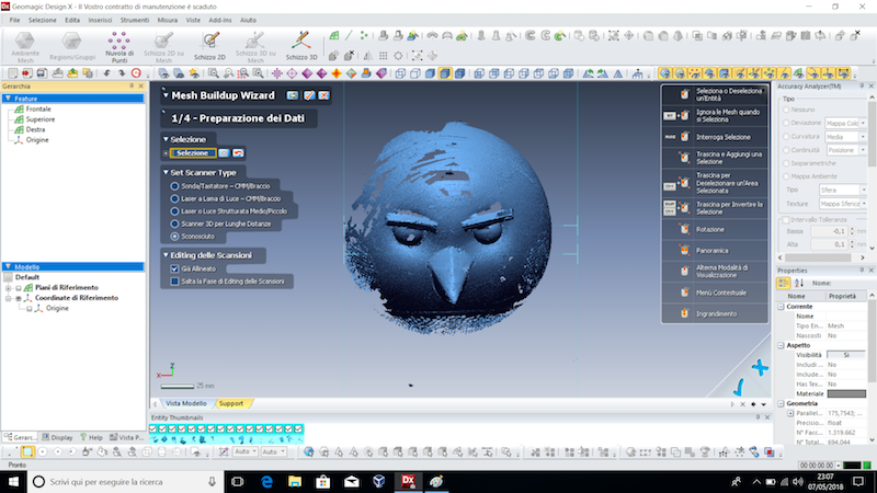
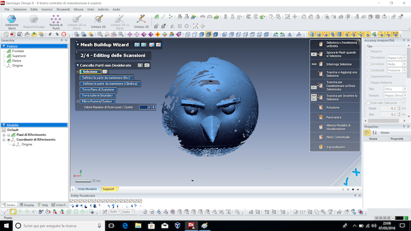
The individual assignment about 3D scanning has been made at FabLab Valsamoggia, because here it is possible to use a Faro Arm, a specific laser scanner for 3D objects. The group assignment has been made at Opendot, and you can check it here.
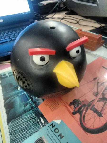
I've decided to scan a funny Angry-Birds-shaped speaker, beacuse it has different sides and some particular details that are quite difficult to recreate from zero.
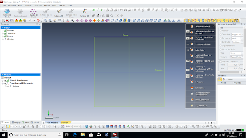
First of all, I've switched on the Faro Arm,
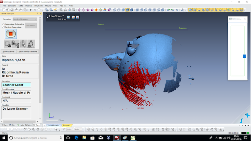
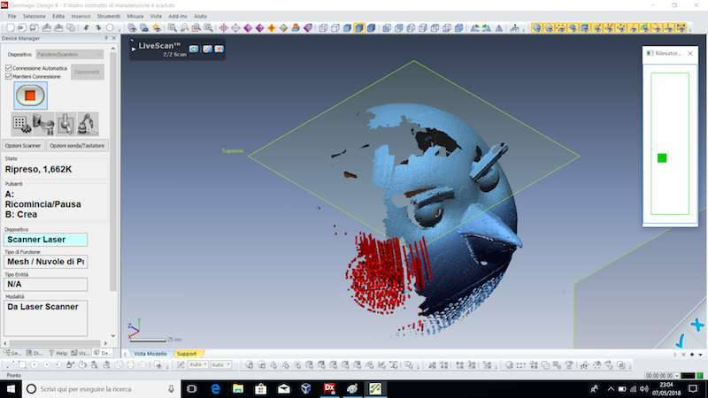
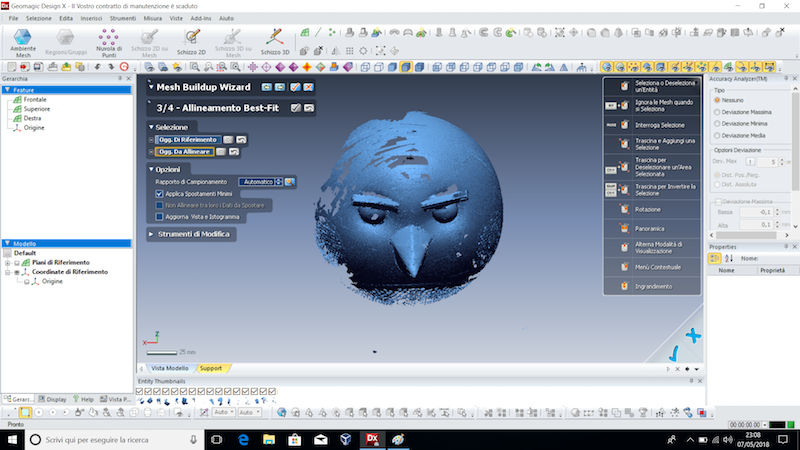
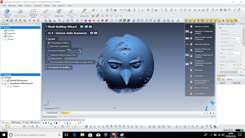
You can download the XLF file here, and the STL file here.
3D Printing
Even this assignment has been made at FabLab Valsamoggia, where I've tested the settings of a Makerbot Replicator 5th generation. Firstly, I've needed to create the model to be printed. I've got inspired by videogames like SuperMario, and designed a tree that is similar to the one in the videogames. I've decided to try again Tinkercad, because for my idea I didn't need to create anything complex.
I've taken a cylinder and set the height to 4 cm, then created two other small cylinders and rotate them at 50°. I've put them on the first cylinder to create sort of branches, and then started to do the foliage with spheres.


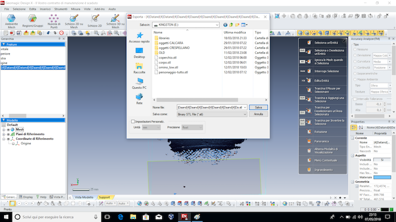
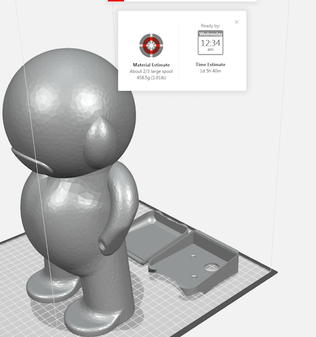
When I was satisfied with the result, I've grouped all the shapes and exported the .stl file. Makerbot printers have their own software to generate the printing file, which is called MakerBot Print. It's a very easy software, with a clean and user-friendly interface.

I've imported as a model the .stl file, and the shape appeared on the plane. The shape was positioned vertically, but I've moved it horizontally to have a better output. I've also selected "Support", in order to have a printed support under the object, especially because of the branches.

Then I've exported the model as a .makerbot file and saved it in a USB stick. I've put the USB in the printer and selected the file I've done. The type of material I've chosen is PLA plastic, because it's a less toxic material, and it's not as flexible as ABS , which is the other plastic material we usually have at the lab.


I've pressed the print button and the print started. The first thing the machine does is heating the extruder.

When the extruder is hot enough, the print starts. As first thing, the machine starts from the support.


The print has lasted 1 hour and 45 minutes, and I've removed from the plate, and also removed the support.


The final object was clean and ready to be used!

You can download the STL file here, and the edition file (.makerbot) here.
6 – Electronics Design
During this week we've to redesign the 'hello-world' board (available on Fabacademy site, and add extra components to it, such as LED, button(s), etc. and test it, while documenting the whole process. You can also check the group assignment here.
Firstly, I've checked on the Fabcademy assessment page the available material, and downloaded the images of the and the board.


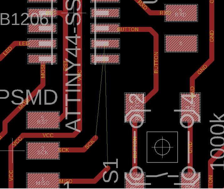
With these images I've managed to redraw the hello-world board. I've started from the schematic:
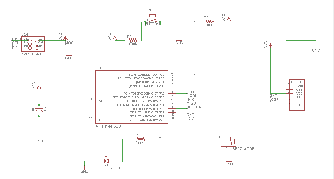
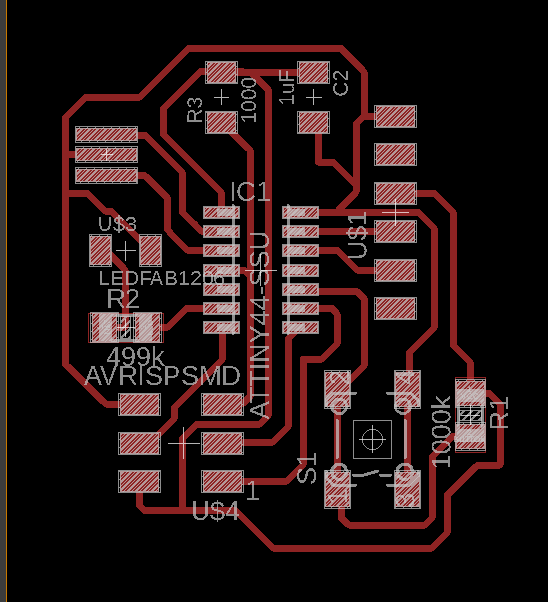
And then realized the board:
The task was to insert in the board a LED and a Button, and to check Design Rules: in Eagle these Design Rules are the settings you define to draw the board. For example, you can specify the distance between borders and tracks, the thickness of the tracks, and so on. These are my Design Rules:
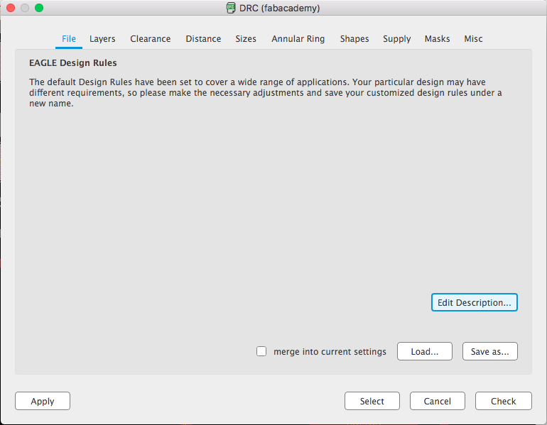
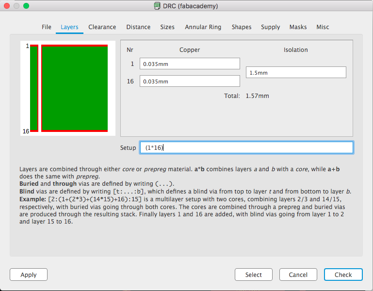
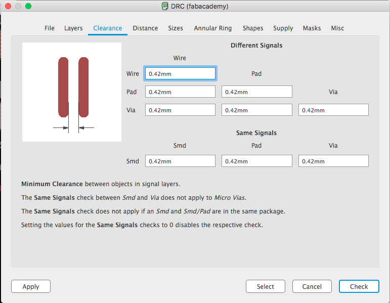
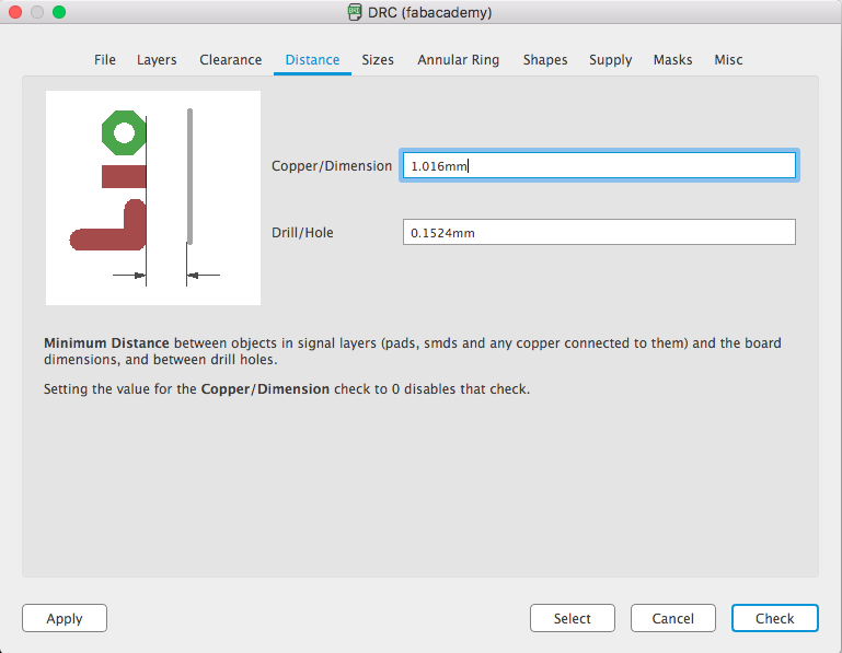
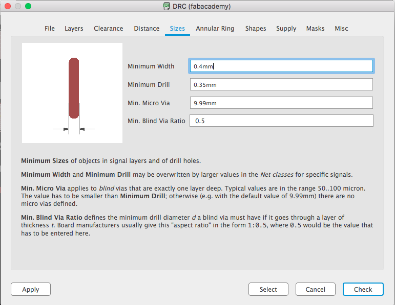
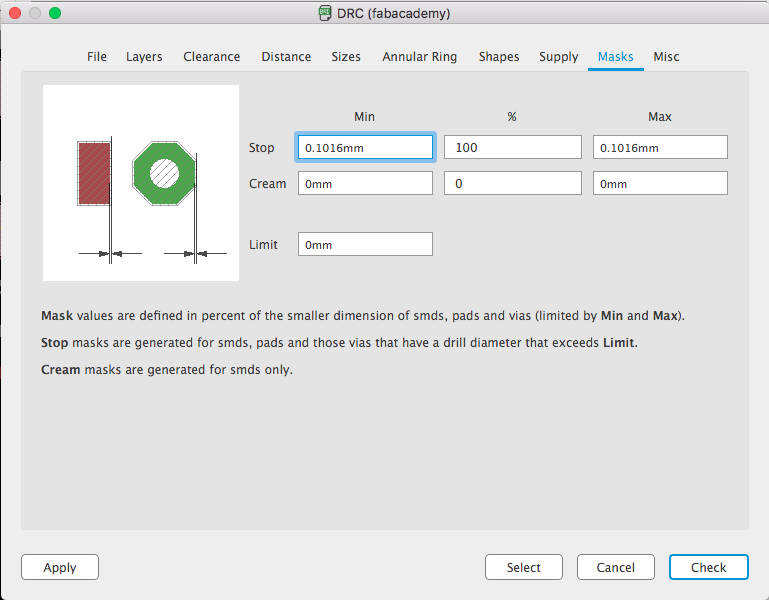
The Design Rules are fundamental to avoid situation where tracks collide each other, in this way:
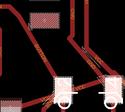
When the board was ready, I've set all the layers as hidden except three (Top, Pads, Vias) and exported a .png monochrome at 1000 dpi. Then I've created in Photoshop the external outline, and saved as a .png with the same dimensions of the previous one.
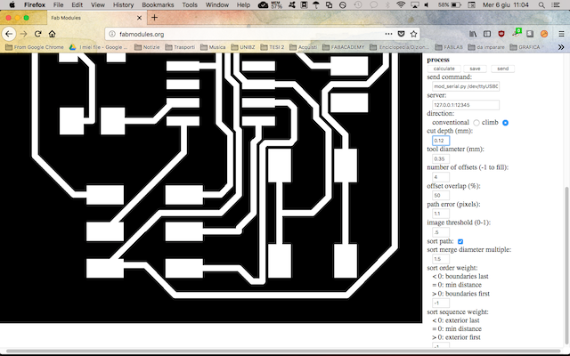
Then I've opened Fab modules in browser, and followed the same workflow I did for Electronics Production: import the .png file, select Roland Mill, select PCB traces 1/64 and then define the settings, with the same tools (0.35 diameter, 0.12 depth), and finally export as .rml file. Through this process you can also verify that the traces are well-separated. I did the same process also for the outline, and then with the two .rml files I started to mill this second board.
I really appreciate the result with the burin, I think it's much better than the bit and less fragile. After the milling phase I took all the necessary components:
So I've started to solder:
After this soldering phase, the next step was to test the board. I've followed the same workflow as for the Electronics Production: using the Atmel ICE with Linux, because it works better than MacOs or Windows for programming.
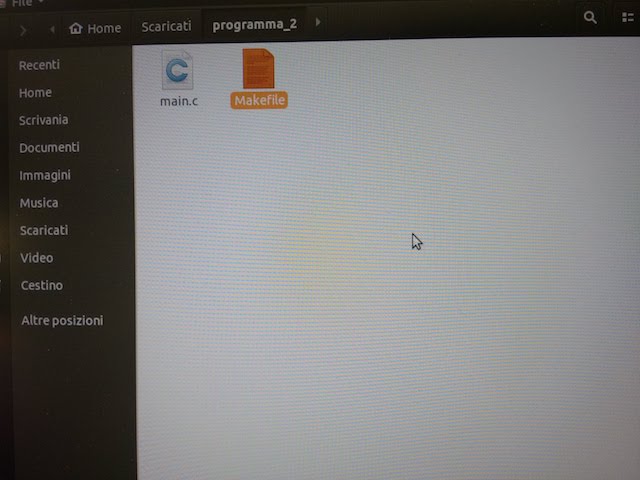
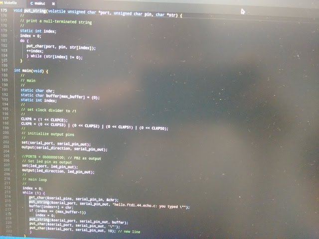
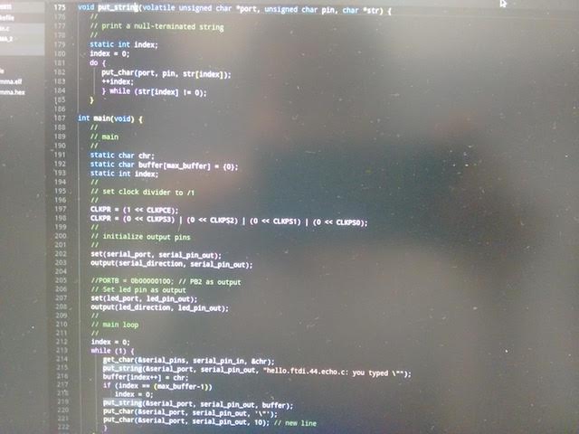
The first step was to create a folder to place the Makefile for the second board and the installation file. I opened the Terminal and wrote nano, which is a command-based text editor. I created a empty main.c file, which is the object of the program. I also copied the Makefile, and place the copy in the folder named "programma2", with the main.c file.
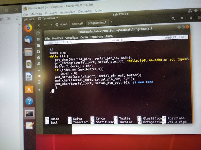
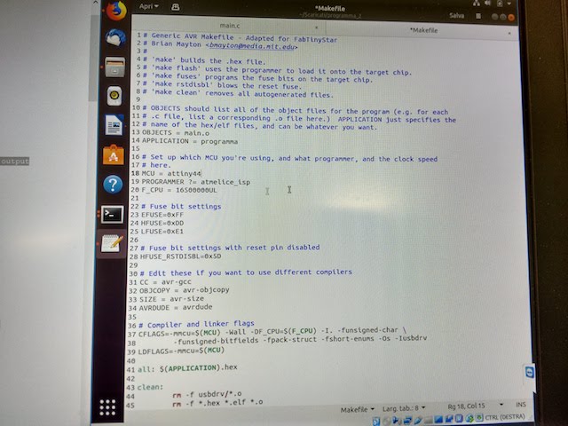
In the make file, you can see that main.c is the object of the program; I set also the MCU, the programmer and the F_CPU (for this last issue one of my Fablab's mate helped me, because I didn't know anything about that).
Then I had everything ready for the creation of the .hex and .hel files: so I run make in the terminal, and it successfully generated the files in the same folder.
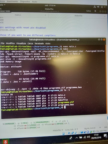
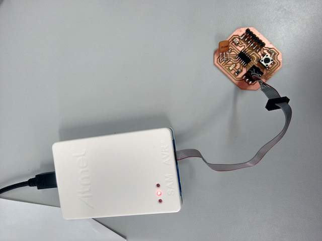
But a problem arised: when we run make flash nothing happened. The green light on Atmel ICE (that stands for power) was turned off, so it means that it wasn't powered.
The most evident problem was that we tried to use a 16MHz crystal, even if the Makefile is set for 20. So we un-soldered the crystal and subsituted it with one of 20MHz.
But still nothing happened. Observing the board and comparing with the schematic and the original hello-world board, I've noticed that MISO and SCK were inverted: on the atTiny44 I had inverted pin 8 and 9, so the atTiny44 would have never being powered.
So I tried one last action: cut away a piece of MISO and SCK and with cable create a jumper from the atTiny and the ISP header.
The idea was good, but it didn't worked. The green light remained turned off. I've had to redesign the board and tried again.
I've changed the design of the board, because I've discovered I've switched the SCK and the MISO pad, so the board would have never turned on. The new design of the traces looked like that:
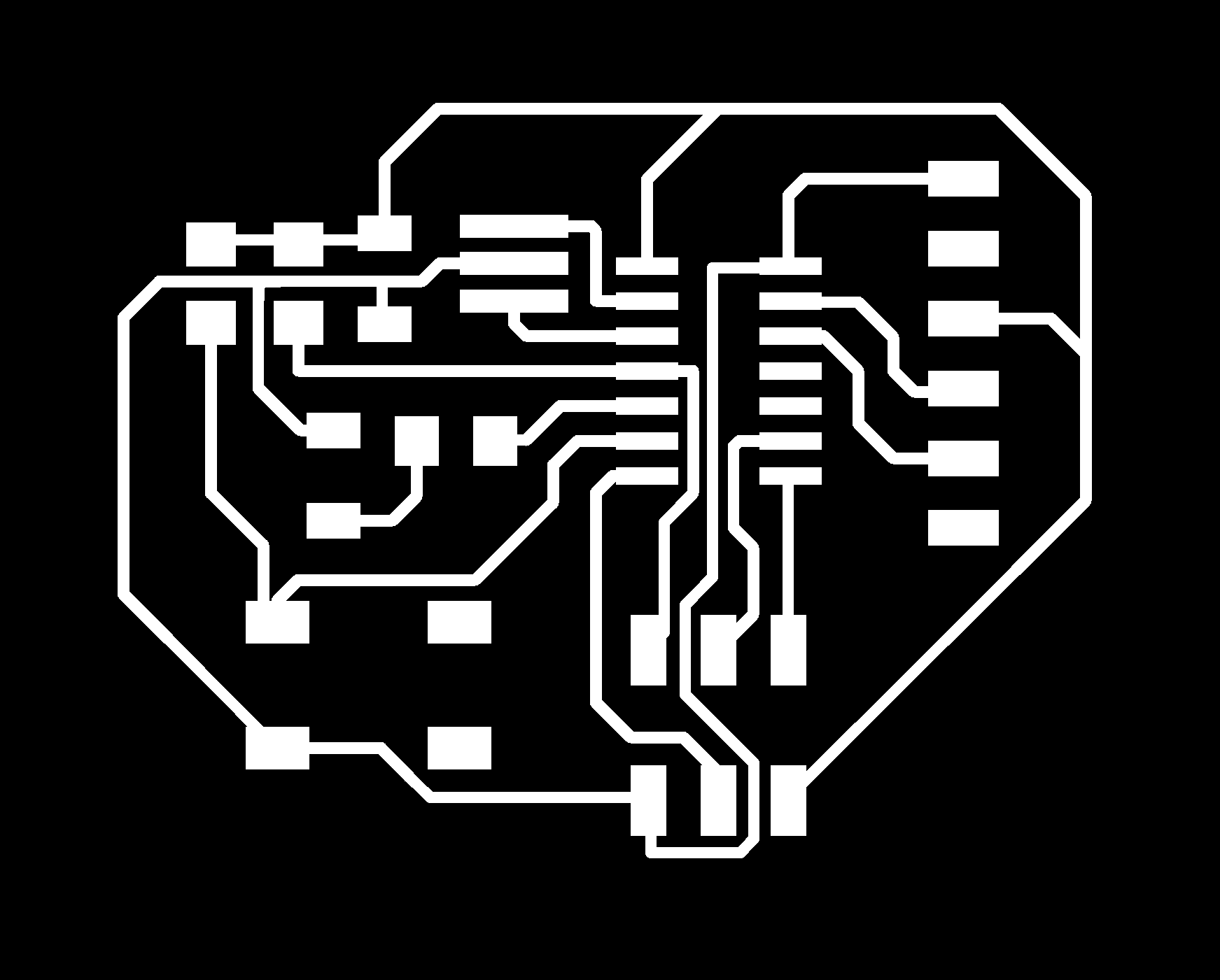
and its outline:

I've put the files in Fab modules and created the G-codes (.nc) for the milling machine, then I started to mill. This time I've decided to mill two copies of the board, because I wanted to use them for the Networking and Communications assignment.
Then I've soldered both of them, and programmed one of them with the FabTinyISP (I've descovered it's easier to use than AtmelICE!).
I've used the same program as before, but changing the programmer with 'usbtiny' instead of 'atmelice':
This time it worked! Everything was in its place and the FabTinyISP has been crucial! The board has beeen programmed and it's ready to be used.
Here you can download:
- The SCHEMATIC and the BOARD file;
- PNG file of tracesand PNG file of outline;
- The folder with the edited Makefile;
- The program folder, based on the previous firmware.
7 – Computer-Controlled Machining
For this week's individual assignment, we were supposed to design and mill something BIG. You can also check the group assignment here.
I'm not so good in 3D modeling, so I've tried to do something easy: I want to do a modular lamp, with two pieces. It's made of two cylinders, one full and one empty. The full one will be the basement, with a circular hole for cables and bulb.
To create the first sketch, I've used Fusion 360. I've started from a cylinder with a diameter of 7 cm and the central hole of 1.8 cm. I've also decided to create some descendant steps from the central hole to the perimeter.


The second cylinder is slightly larger than the first one, because it's its "protection"; it will low the amount of light generated by the bulb, and create effects.


When I finished the two models, I entered the CAM section, create a new Setup and define the type of manufacturing I wanted to obtain.


I've chosen 2D > Circular, to do the holes, and 3D > Adaptive Clearing for the rest.

I've also needed to create a bigger object, and I've decided to create a case for amplifiers:

I've done a sketch and a model in Fusion 360 for each side, starting from the front with two holes for the sound and one smaller hole for cables.

I've created a New Setup and chosen 3D Adaptive Clearing for a predefined CAM: since I've to use just two axis of the milling machine, this option is prefectly suitable because it recognizes automatically the surface to be milled.


Then I've exported the G-code adapted for Mach3Mill, which is the software I've used. I've started with the front side:

and then started to mill:
VID_20180625_220159241 from federicaselleri on Vimeo.
VID_20180625_220948081 from federicaselleri on Vimeo.
When I've finished to mill each side, it looked like that:

I've used almost 10 screws for wood to build the case, and the final result looks like that:

I've also needed to design another object, this time with joints. I've decided to create a squared box with 6 faces, because in our FabLab in Valsamoggia there's always quite a mess on the table. Especially sandpaper is always scattered all over the table, so I wanted to give a sort of order.

First of all, I've created a sketch on Fusion 360, but just three faces because it will be specular, so these three faces will be just duplicated.
Joints are different on the three faces, because I've discovered (after many many many trials) that spaces between joints have to be larger than the joint, and related to the thickness. In addition to that, there must be a face with the "opposite" joints from the other two; in this way you can add always more faces if you want to enlarge the structure.Then I've add a slot on a face, in order to create a handle to open the box.

I've finally extruded the sketches. The height of the extrusion is the same of the stock's height (a wooden panel), and in this case it's 1.8 cm.

When the model was ready, I started to create the CAM for the CNC machine. I've opened a new setup and then selected the option 3D > Adaptive Clearing.

I've set the CAM with a bit of 5.7 mm of diameter, and these are the values I've set:


After that, I've exported the G-code (as a .tap file) and imported into Mach3Mill, our software for the CNC machine. I've arranged the wooden panel inside the milling machine, set the origin of the axix (here we normally set it in bottom left) and then started the work.

It took almmost 50 minutes (I had to stop sometimes to check if everything was fine), but the result was satisfying:


Even assembled it's not bad:


The table now looks better!

The box is a perfect sandpaper container!


However, in this case I've used a 3D workflow, and I had to try also a 2.D workflow. Not all the CAD softwares allow you to create both 2D and 3D CAM, but luckily Fusion 360 doeas. So, I've edited a bit the model (adding an engraved text with a depth of 5 mm) and re-created the proper CAM. After some researches I've noticed that Fusion has several types of 2D manufacturing: you can choose between several options, according to the kind of result you want to obtain, the type of model and material, and the tool you're using. In this case I've used two actions to mill the final box: 2D Contour, for the external boundary and the circular hole, and 2D Pocket for the engraved text. I've made dogbone cuts using slots, and the height of the joints MUST be the same of the material's thickness (it's crucial, or your joints won't be planar)

To create a good and easy 2D Pocket, you need to select the BOTTOM boundary of the shapes, otherwise Fusion 360 can't elaborate the correct path.

Another important option to consider is the placement of tabs, small pieces of stock material that the tool "jumps" in order to keep the model fixed while the manufacturing takes place.

Fusion 360 allows you to constantly check how will be the path of the tool with a simulation option. I've checked each workflow:


After that, I've exported the G-code (always a .tap file) and placed inside Mach3Mill. Then I've turned on the machine and the manufacturing has started.


The final result is really satisfying: it took quite the same as for the 3D manufacturing, but I've needed less material.


You can download the Fusion file of the lamphere, and the files for the amplifier case here, and the box files (STEP and g-code)here.
8 – Embedded Programming
The individual assignment is included in my final project, and it consists in the board I've designed for my final project. I've tried three different designs before find the correct way to arrange all the components. You can also check the group assignment here.
The very first trial had too thin paths and vias, and the milling machine cut away most of the tracks. Even Fab modules had some problems while creating the CAM files for the milling machine.
So I've made a second trial, enlarging the paths and using a different width: instead of 0.4 mm, I've tried 0.6 mm.
This time Fab modules had no difficulties in creating the G-codes, and I've milled the second board.
I forgot to use sand paper to finish the surface, so it was a bit rough and the pads weren't so much clear. I've soldered PTH components becuase some of the SMD I've ordered weren't available on time.
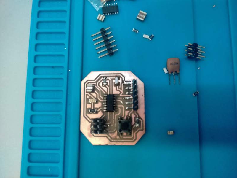
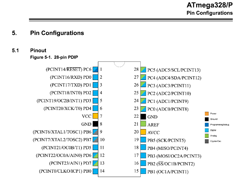
Unfortunately, this board had some issues also during programming, and it was definitely too big for the integration with the 3D part. So I've redesigned it. I've changed the ATtiny45 with an ATmega328, which has more memory and hopefully less troubles for the programming. I've also read carefully the datasheet of Atmel ATmega328 micro-processor, to be sure I've understood correctly the pin arrangement:
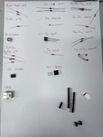
This is the list of components I've used:
- 4x 100 nF capacitor
- 4x 0.1 µF capacitor
- 1x 10 µF capacitor
- 1x 22 uF polarized capacitor
- 1x SMB Diode
- 1x USB type-B
- 1x FT232R (USB UART-IC)
- 1x ATmega328
- 1x Positive Voltage Regulator
- 1x 1x3 PIN header
- 1x NeoPixel FeatherWing 4x8
- 2x 68R Resistor
- 2x 330R Resistor
- 6x 1K Resistor
- 3x 10K Resistor
- 1x 100K Resistor
- 1x 1M Resistor
- 2x Switch SMD
- 1x Omni-directional electret microphone
- 1x LM386 Low Voltage Audio Power AMplifier
- 1x BERG USB connector
- 1x Resonator 16MHZ
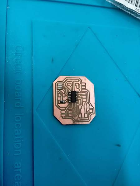
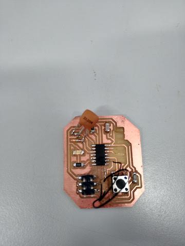
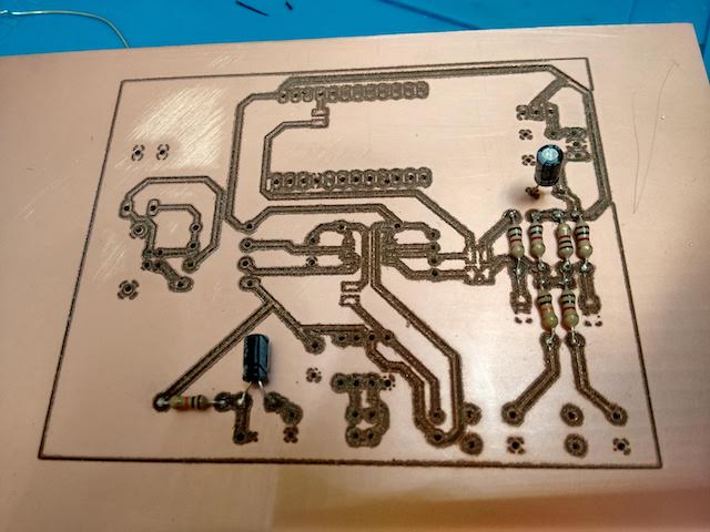
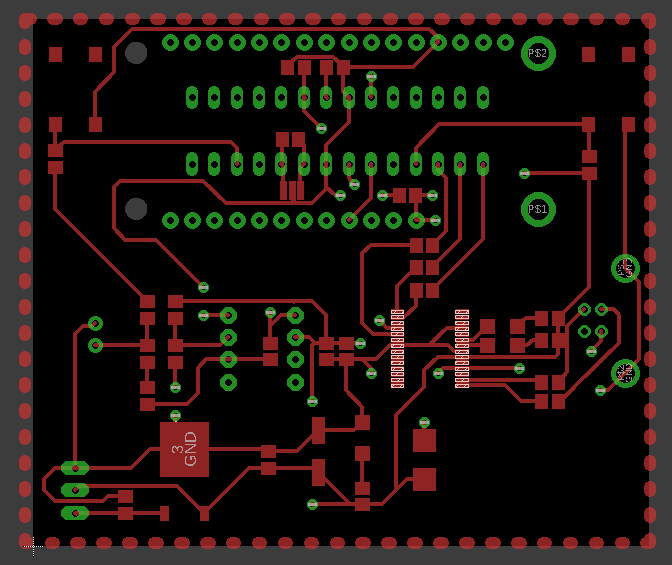
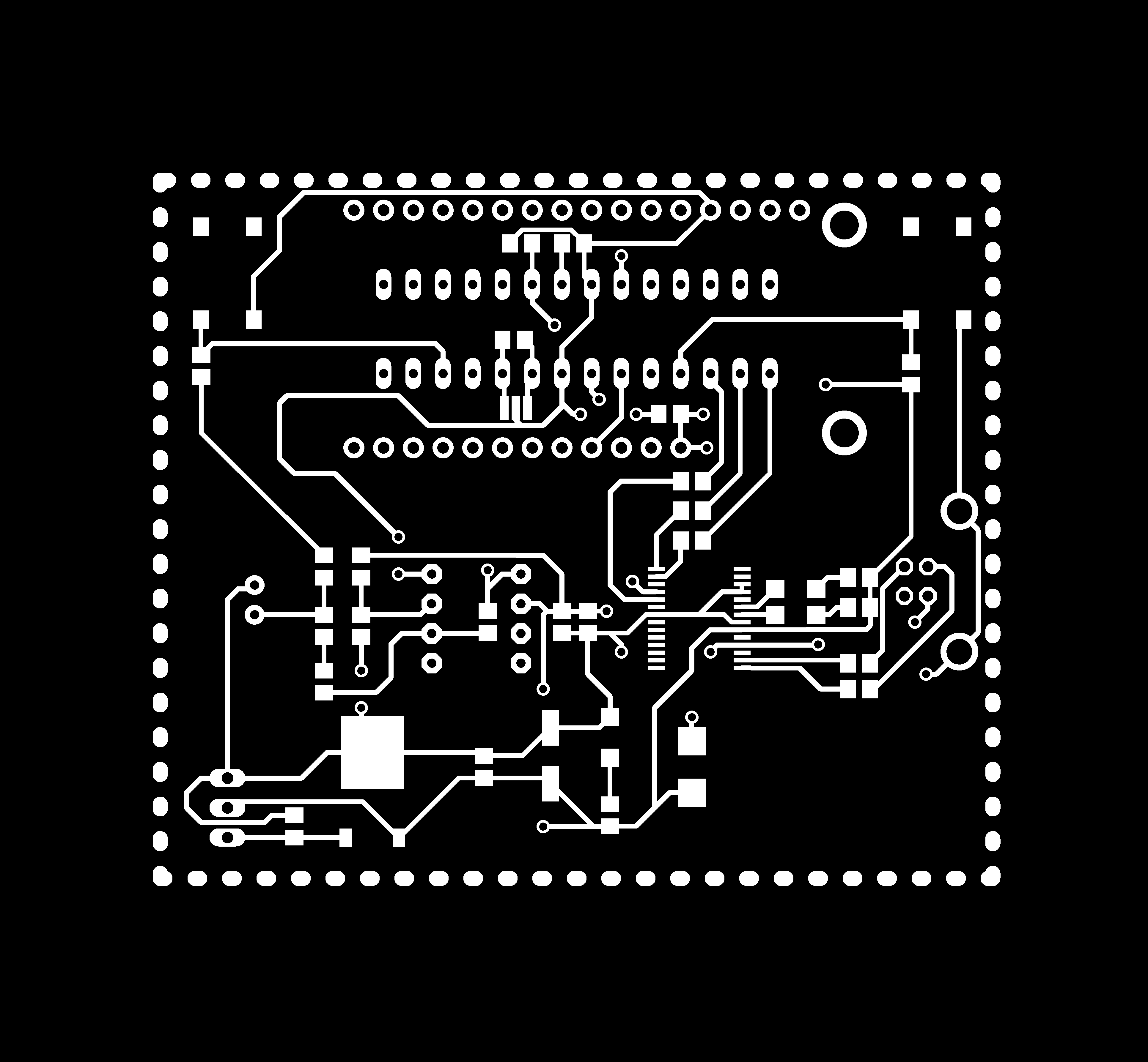
This time I kept the pads of 0.6 mm of width, and the milling machine had no big issues during the fabrication. I've also finished the board with a 500 sand paper, and the result was really satisfying.
I've chosen a PTH component (the ATmega328) mostly because the smd components hasn't arrived in time for the end of the project, and because I can put it in the back of the board, so it's not visible. The ATmega has more memory than Attiny45, and in this case it has been the best choice.
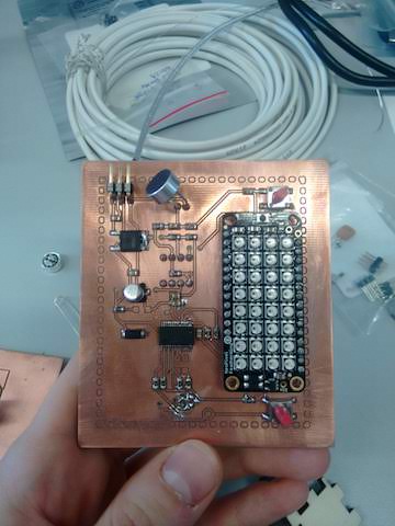
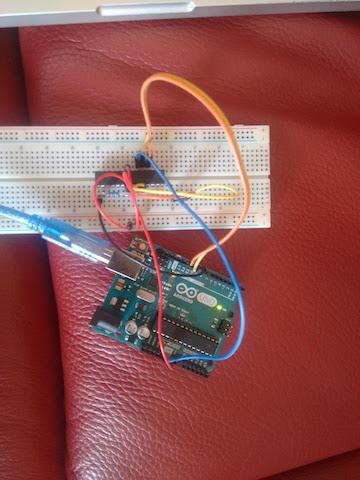
This time I've tried to use Arduino as bootloader to program this final board. ATmega328 is the same micro-processor installed in most of the Arduino boards, and the IDE has a precompiled sketch for programming compatible boards. I've programmed the ATmega328 separately from the board, and soldered it lately. To program ATmega328, you can place it on a breadboard and connect it to an Arduino board, in this way:
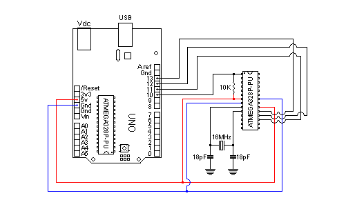
You have to open the sketch "Arduino ISP" and upload it on the Arduino board you're using, in my case an Arduino/Genuino UNO.
You can plug the Arduino board, and then select what kind of bootloader you want to upload in your board:
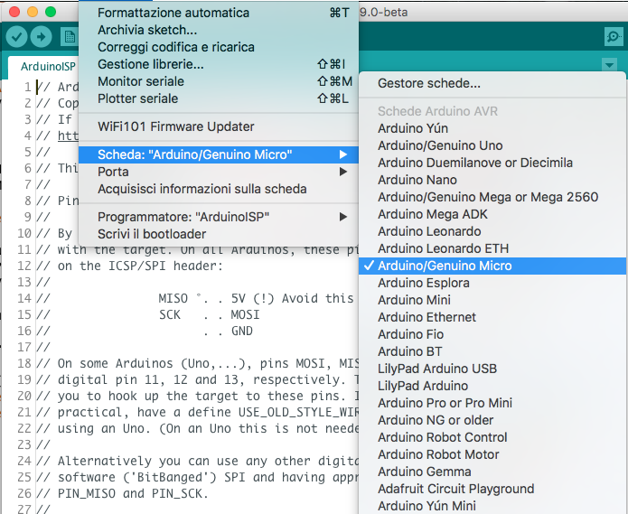
Then you can run the bootloader, in Tools > Burn Bootloader:
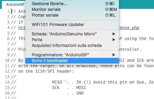
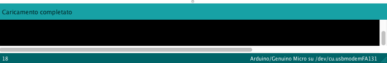
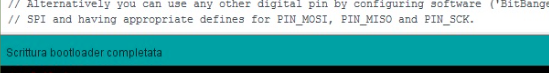
When the bootloader has finished, a message will appear in the editor.
So the micro-processor has been programmed, and it's ready to be put in the board. I've placed the ATmega328p under the board, in order to optimize space for the LEDs and the rest of the components on the board.
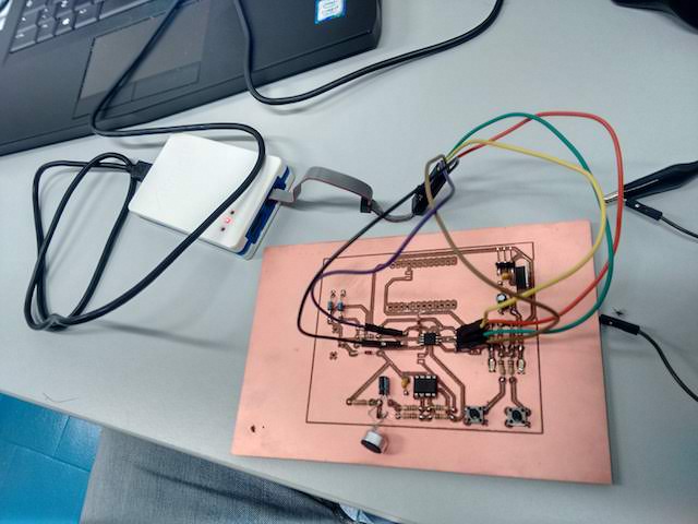
To connect the micro-processor and the computer I've used a FT232R (USB UART-IC), in this way the computer with Arduino IDE can communicate with the board (the ATmega328 is a PTH component soldered with the traces on the top layer). This chip is a USB <->UART chip. It is used to allow a PC, using the USB bus, to communicate with MCU chip on some models of Arduino. Thanks to this component you can upload Arduino sketches on your board. Also the USB connector is soldered on the back, in order not to have cables on the top layer. Cables are hidden inside the leg.
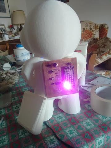
Here you can read the datasheet of the component I've used. When I've plugged the board via USB, I've tested if it was working properly by turning on one LED:
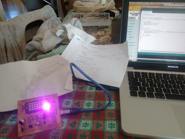
It worked!
You can download the schematic and the board file here.
This is a tutorial I've followed to program the micro-processor.
9 – Moulding and Casting
The individual assignment for this week was the following: "Design a 3D mould around the stock and tooling that you'll be using, machine it, and use it to cast parts." You can also check the group assignment here. I've decided to try to relate even this assignment into my final project, to have a sort of bond among all of the various assignment. First of all, I've sketched the shape of the 3D object I was about to design, and I've chosen to do an optional tool for my educational puppet.
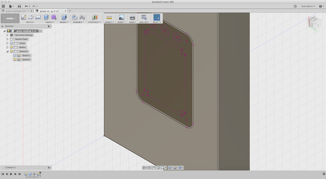
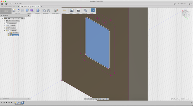
I've used Fusion 360 to create the sketch needed to create the mould.
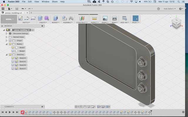
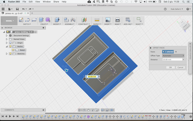
I've projected the sketch on a rectangular solid I've generated, and then extruded some parts I wanted to have. It's important to create a channel for casting and a channel for the air, in order to avoid bubbles.
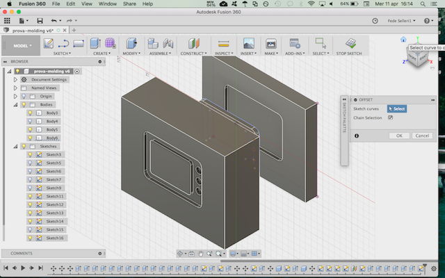
I've created also a small step around the two pieces in order to facilitate the joint and the casting.
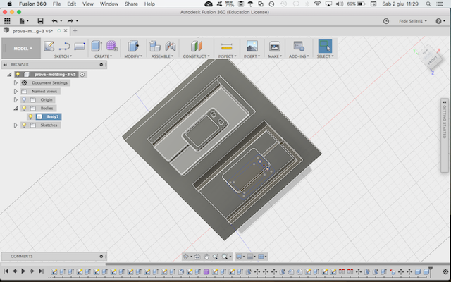
These are the two objects that have to be milled.
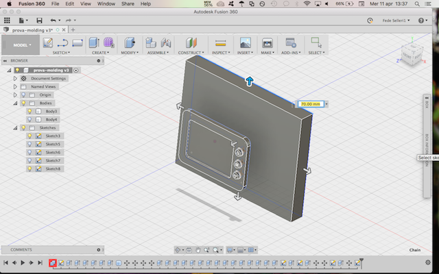
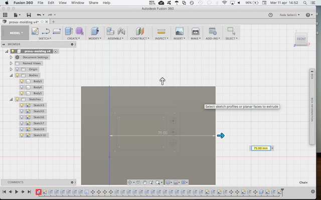
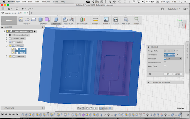
After that, I've had to create the external container for the two mould (I'd like to call it "counter-mould"), which is a rectangular box around the two.
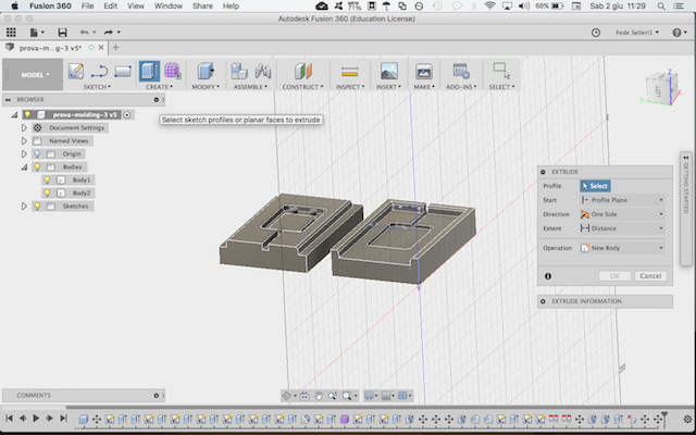
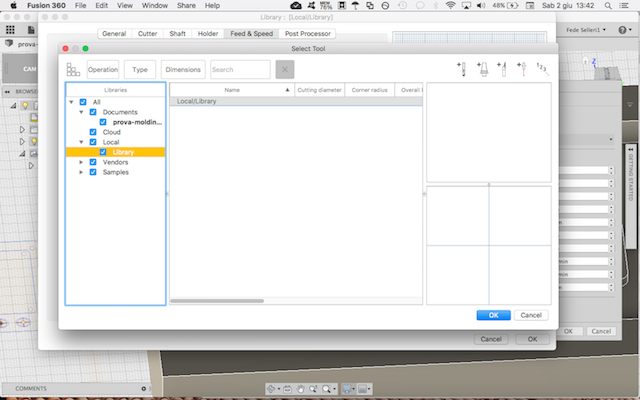
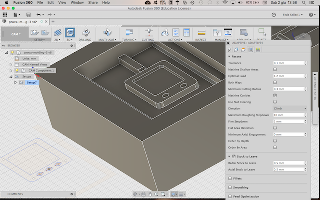
When the model was ready, I got into the CAM part, which is integrated in Fusion 360. You can click on "model" in top left, and select "CAM". You need to create a New Setup (Setup > New Setup in the top bar), and then choose the type of manufacturing you want ot use.
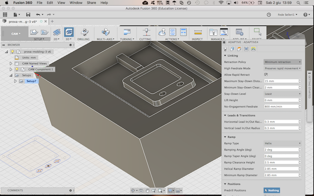
I've chosen 3D > Adaptive Clearing, because it's a workflow that let you avoid to set each layer. You just have to set the type of tool you're going to use, the starting point of the axis and the offset. Then Fusion will calculate the paths. If you double click on "setup" in the left column, it will open the Tool library: here you can add a tool from the library or set a new one.
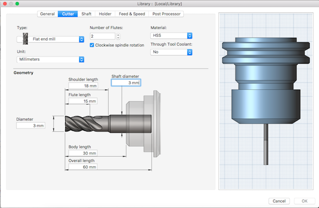
I've selected a new one, and I needed to define the type of cutter,
and the speed,
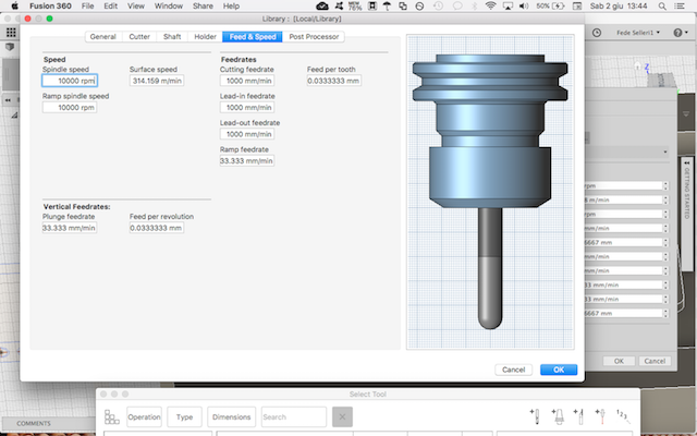
and after pressing OK the tool will appear as saved in your library. You can also rename the tool.
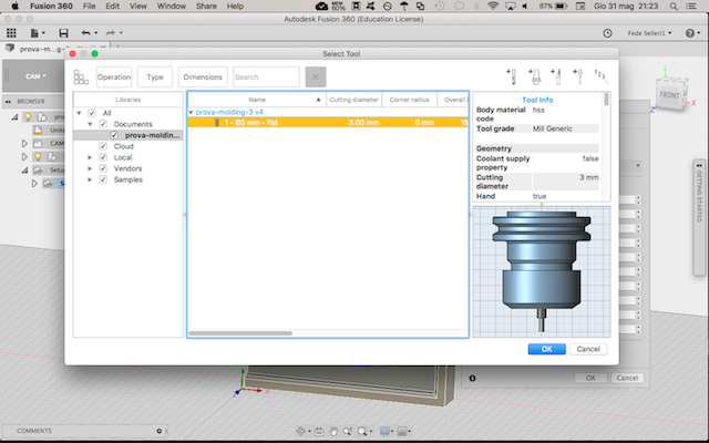
At this point we can check the settings on the Adaptive panel on the right:
When you complete the settings, you can simulate the operation of the mill, by selecting Actions > Simulate in the top bar:
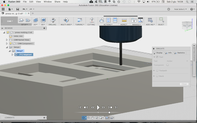
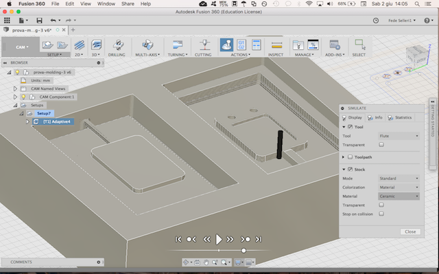
If the simulation is ok, you can right-click on Setup in the left column, and select Post-Process: it will ask you where to save the G-Code file generated by the software (the G-Code gives the coordinates to the mill for work).
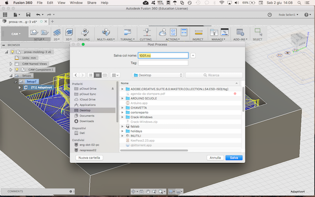
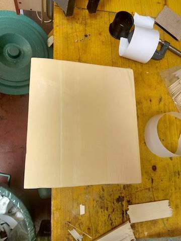
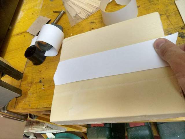
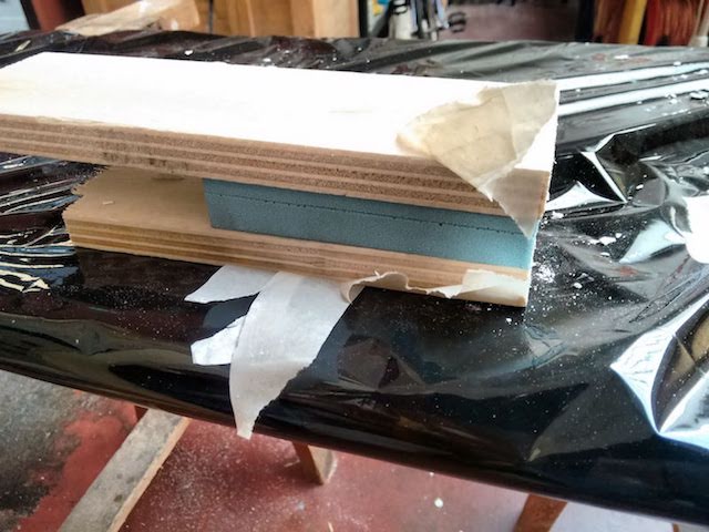
I've saved the .nc file on a USB stick and attached in the PC connected to the milling machine. I''ve also had to prepare the styrofoam for the milling: I've cut a piece of 20x15 cm and put some double-sided tape under it, and then attached it on the plate of the milling machine.
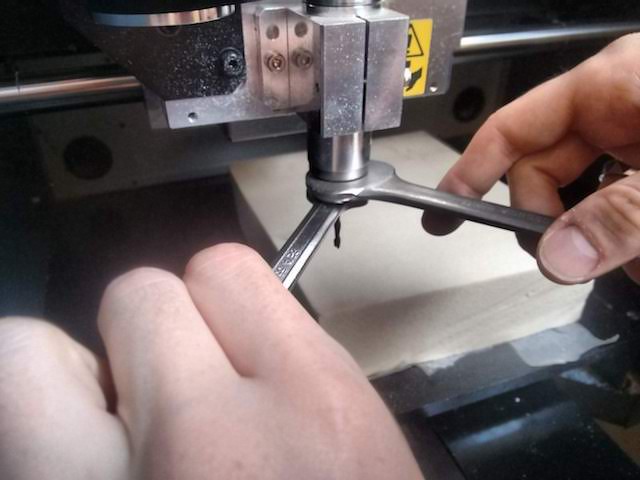
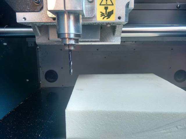
I've changed the bit with a 0.3mm
Then I've set the origin of axes X.Y, and Z in the same way I did for Electronics Production, and then upload the file and press Cut.
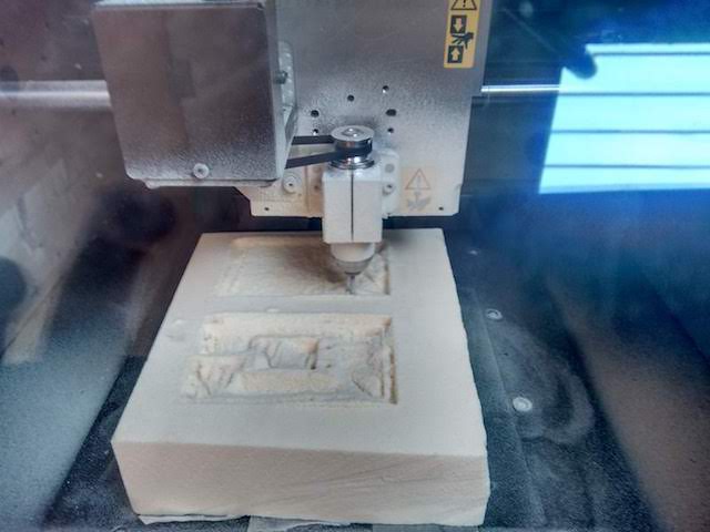
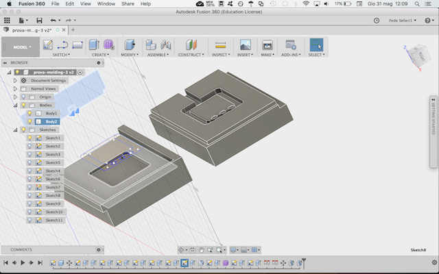
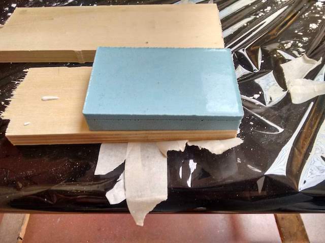
The result was satisfying:
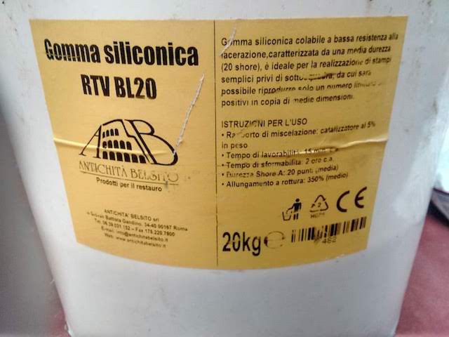
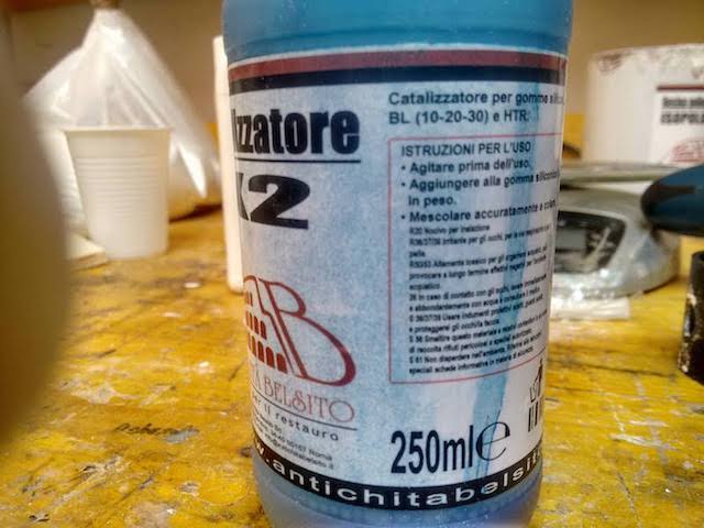
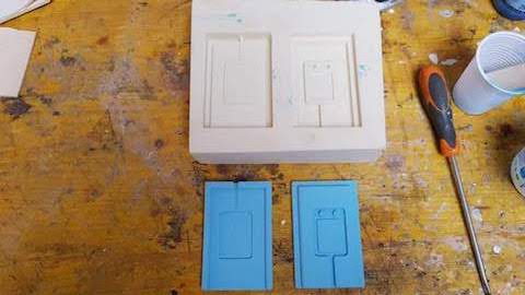
Then it was time to cast and create the moulds: I've used silicone rubber becuase it's quite easy to do, you just have to mix the rubber with the catalyst in a specific percentage.
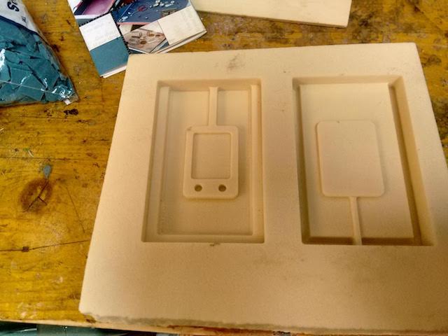
I've mixed the two components in a plastic container and then poured slowly in the moulds.
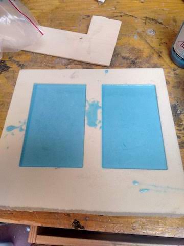
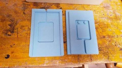
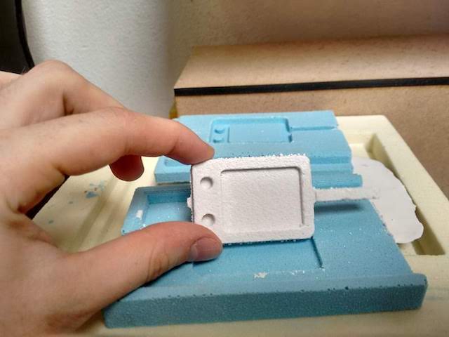
After two hours I've removed the moulds from the counter-mould, and the result was pretty good:
then it was time for the last part of the assignment: cast the part. I've use ceramic plaster to create the part, because it's a very simple material that has a great aspect once finished.
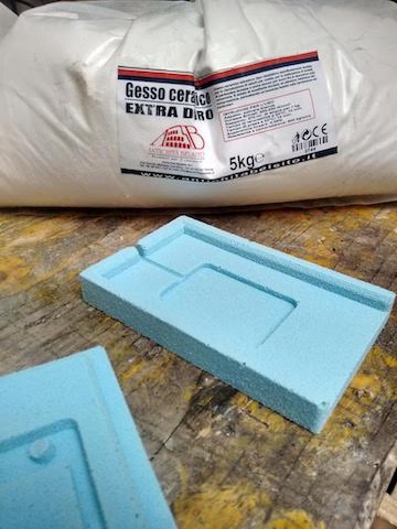
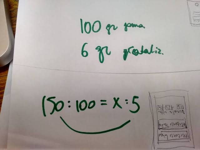
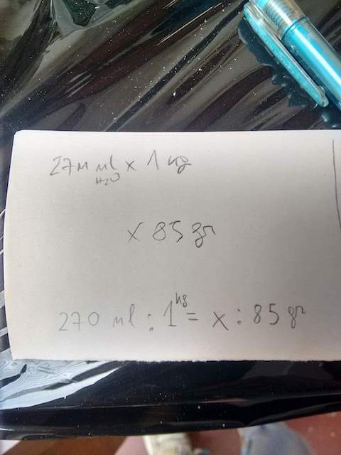
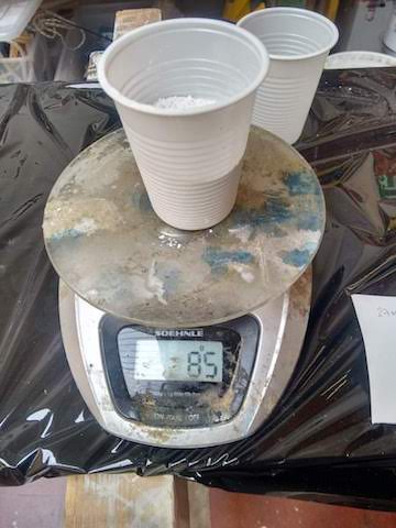
Also in this case I've needed to calculate the correct amount on plaster and water: the given percentage was 270ml of water for 1kg of plaster. I've needed less than 1 kg, almost 85 gr and 23 ml of water.
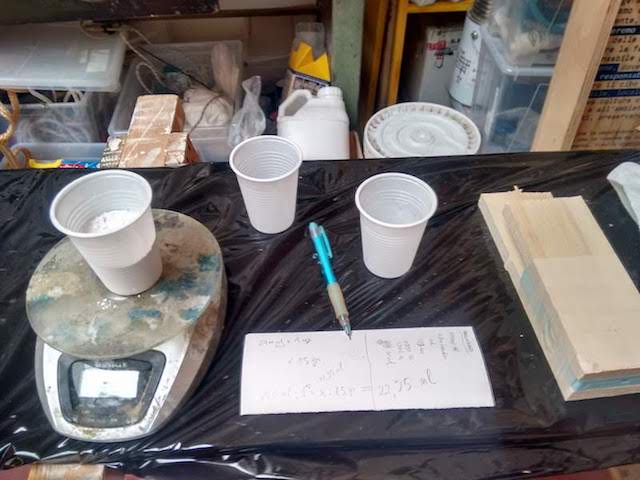
I've mixed the components and drain them into the moulds, which I've kept closed with tape and wooden bars.
I've waited for 20 minutes, and then I've broken the tape and open the moulds:
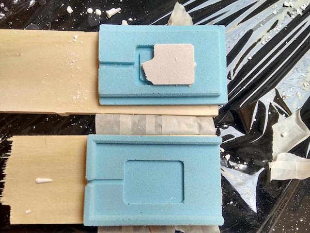
In this case the result wasn't satisfying, because the plaster didn't reach all the parts of the moulds. So I've decided to try again, but this time keeping the moulds vertically and not horizontally as I did before. I've had to close the air channel with tape, to avoid plaster pouring out.
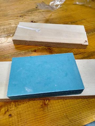

This time the experiment succeeded! I've taken out the small object, and eliminated the air channel.
You can download the .TAP and edition file herefor the milling machine, and the STEP file here.
10 + 11 – Input & Output Devices
In this week's individual assignment, the task was to design a board by ourselves, thinking what kind of output and input we need on our board, maybe related to our final project. You can also check the group assignment here. This indivual assignment is included in my final project, and it will be updated soon.
I've decided to insert as INPUT a Sound Detector, and I've taken this one as inspiration:
it will let the puppet to turn on when it detects a loud sound (such as clapping hands).The OUTPUT I've chosen is a sort of LED matrix: I've decided to use a NeoPixel string of 4x8 LEDS, because it's a reliable product and has enough LEDs to create letters and shapes.
I've done some sketches about the final board, which includes also various assignments such as Input&Output:

I've started to create a schematic, inserting all the components I want to use:


Initially I've placed a atTiny85 (you can find the data sheet here), but after I've realized that it hasn't enough memory for what I've planned, so I've changed it with an ATmega328.
I've redesigned the board in order to use most SMD components with a PTH ATMega 328. To upload the bootloader on the ATMega I've used a FTDI component. This is how tho board looks like before the machining:

The final board is also smaller than the first one, because it has to be located in the back of the puppet (inside a sort of bakcpack). So I've tried to use both of the sided of the board, placing the ATMega in the back.
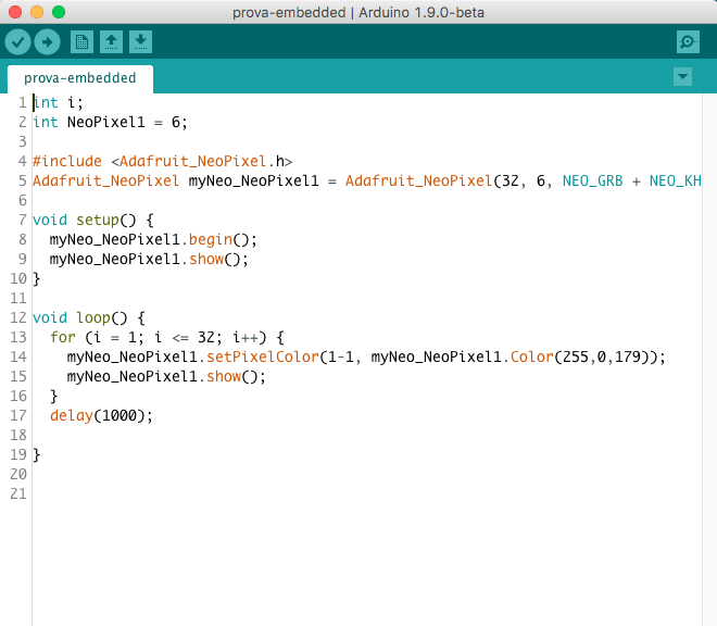
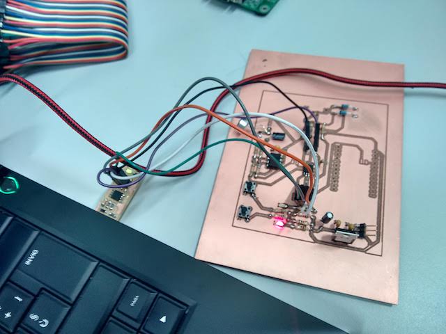
As INPUT device I've used an Electret Microphone, which will turn on the OUTPUT (the NeoPixel Featherwing). I've used FabTinyISP to program the board, and then I've created a sketch with Arduino IDE to control the microphone and the NeoPixel:


Here's the complete code: #include
I've tested the microphone with an oscilloscope to control if the microphone receives the signal properly (I was whistling):
VID_20180626_113618740 from federicaselleri on Vimeo.
The microphone worked quite well, so I've connected it to the Neopixel and tried with a louder sound:
final3.mp4 from federicaselleri on Vimeo.
It works!
You can download the Arduino sketch here, and the schematic and board files here.
12 – Interface Programming
The indivual assignment is included in my final project, and it will be updated soon.I'm going to use Processing, which is a C-based software for graphic animation.
I've connected also this assignment to my final project, because I want to design an interface for the educational puppet.
Initially I've designed a interface to control the colors of the NeoPixel. I've decided to use Processing to create a dynamic interface. I've reused the same library as for the Machine assignment, the ControlP5, and a sketch named ColorPicker. I've created a "picker" for each LED, so you can control the color once the board is turned on.
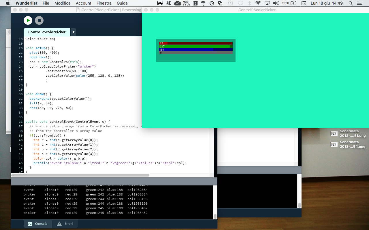
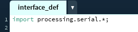
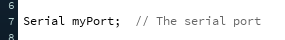
To connect Processing with Arduino IDE you need to open a "Serial Port", by simply importing the serial library on Processing and creating a Serial Port:
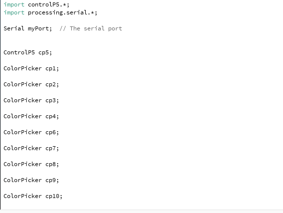
I've also created a Color Picker for each LED as a variable, and then used them to create the visual Picker:
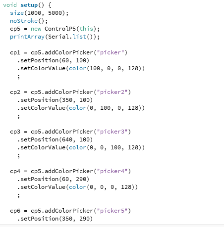
I've set the position (X,Y) of each picker, and the range of colors I wanted to have. Then I've created an ellipse of each picker, to show better the chosen colors and help the users to decide which color use and in which position.
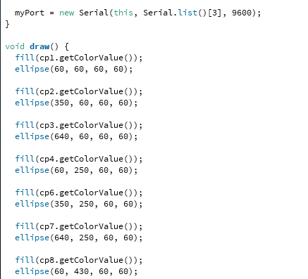
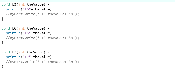
Then I've used a function for each picker to send the input to the serial port connected with the board. Processing will send the RGBA values for each picker.
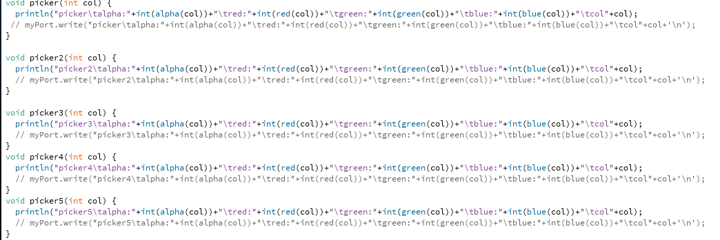
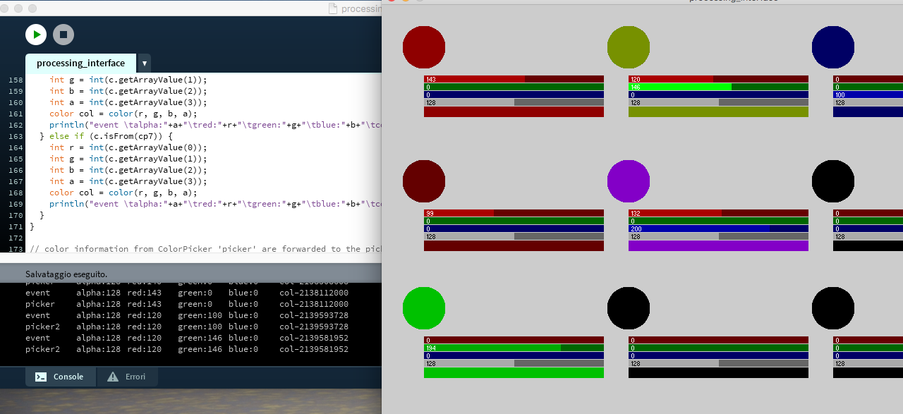
Here it's how it looks like with the first 9 pickers, you can see that by controlling each of them a message is printed in the serial monitor of Processing.
But after I've finished this interface, I've realized that I had few time left to connect it to Arduino, because it would have taken too much time to connect each picker value in RGB to Arduino. So I've changed a bit, and decided to create an interface to turn on and off each LED of the Neopixel. I've started from an example of the ControlP5 library, named Toggle: I've chosen this example because I've needed a way to show if something is pressed or not, and also allow the user to keep a LED turned on.
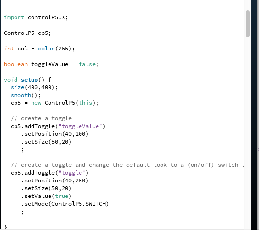
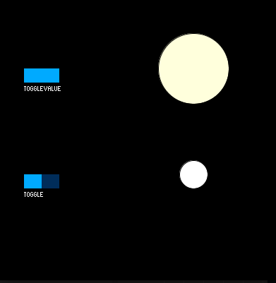
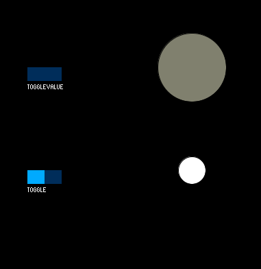
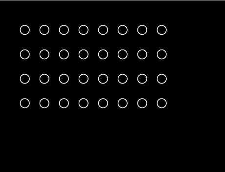
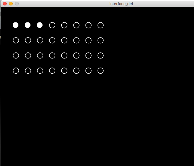
I've prepared the images of 20x20 pixels of the white ellipse and the black ellipse with a white outline that stand for the controlling button of each LED.
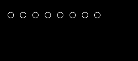
The black ellipse with white outline stands for a turned off LED, while the white ellipse stands for the turned on ones. I've replicated for 32 times the toggle, in order to control each of the 32 LEDs of the NeoPixel.
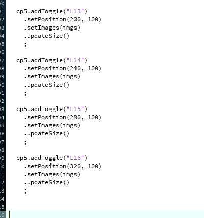
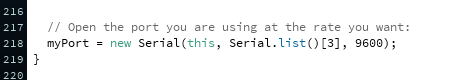
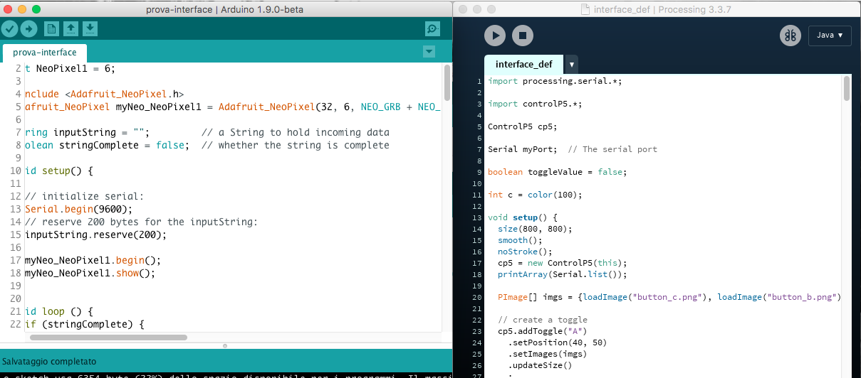
I've also needed to establish a communication channel between Processing and Arduino, and to do so I've opened a Serial Port by importing the Serial library (default on Processing 3) and created myPort, inserting the number of the serial port (and the number must be the same used on Arduino).
After that, I've established a connection between each toggle and the serial port:
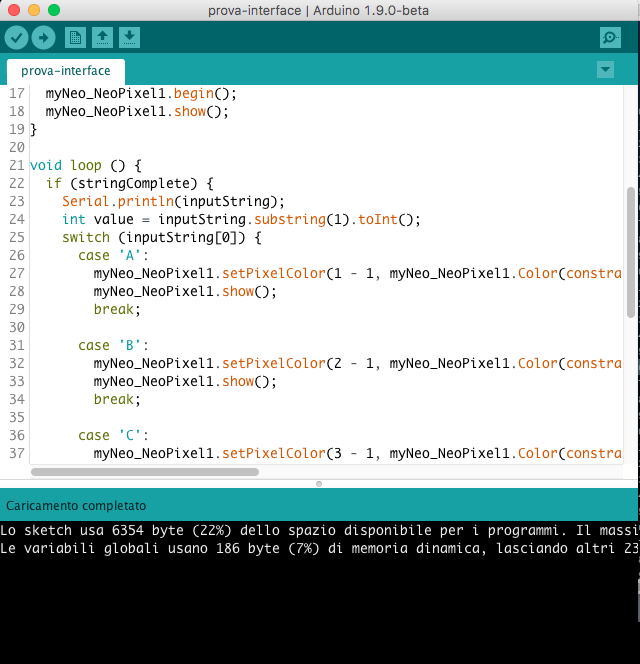
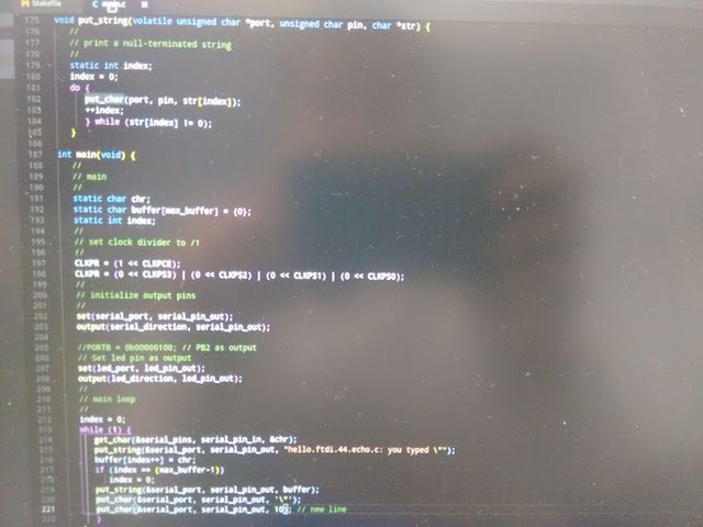
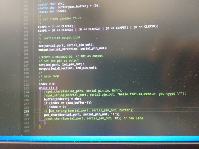
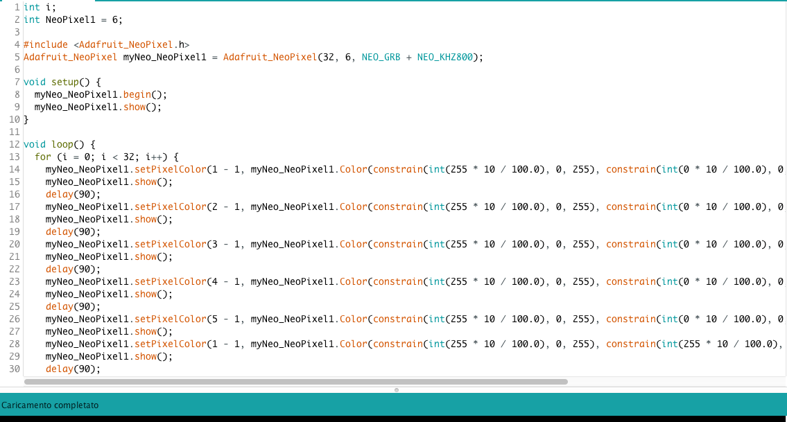
Then I wrote the code in the Arduino IDE:
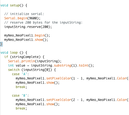
I've used the same serial port of Processing, and create a string for each value that comes from Processing. In this code the chosen color is white, and you can change it by changing the value in each string:

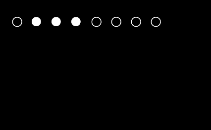
Then the code was ready to be tested: at first I've run the code on Processing, and turned on the first three LEDs by clicking on them (they remained on until you click again on them):
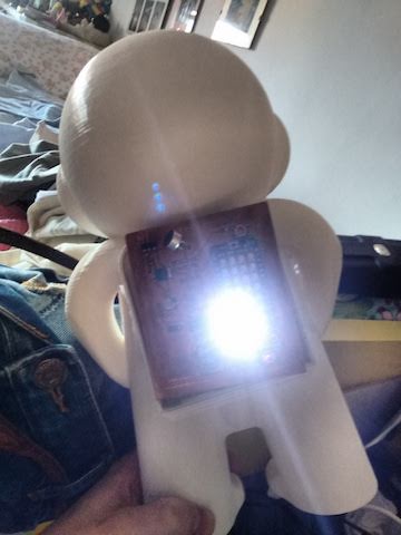
After that I've uploaded the code from Arduino to the board:
LEDs 1,2 and 3 turned on:
You can download here the Processing code and Arduino code.
13 – Embedded Networking and Communication
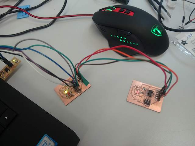
For this week's assignment we were supposed to connect at least two processors, with a wired or wireless connection. I've tried to do a wired connection with two helloworld echo boards. You can check the group assignment here.
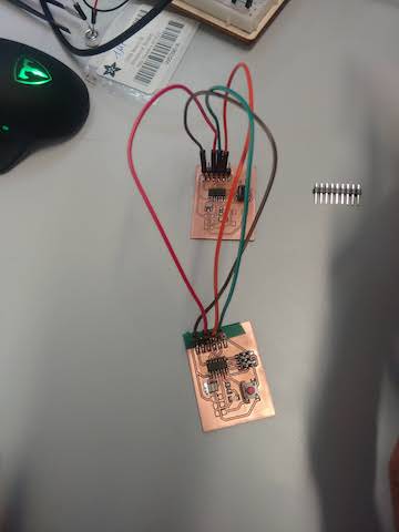
I've milled two echo-helloworld boards, and I wanted to make them communicate each other, for example to turn on a LED from one board to another. Firstly, I've soldered the two boards with almost the same components, and two ATtiny44 as micro-processors.
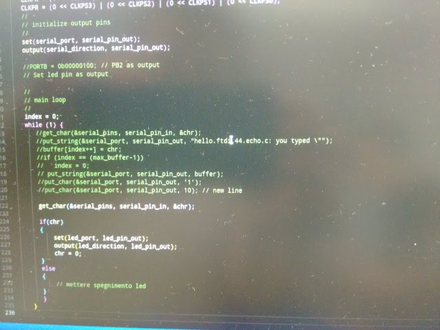
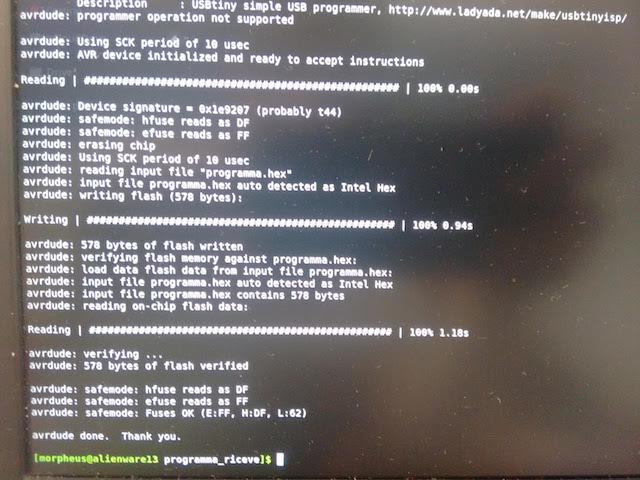
Then I've used the good old FabTinyISP as a programmer (still while using Linux), and I've programmed the two boards separately. I've reused the same programming configuration I've used for the echo boards, but creating a new program.
The I've created a new program for the second board (the receiver). At this point I've tried to plug the second board in the header pin of the first one, connecting RX and TX.
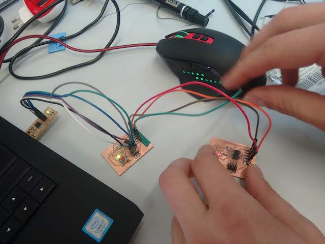
It worked! I've sent the information from the first board to the second one to turn on the red led!
You can download the programming files here for the sender and here for the receiver.
14 – Mechanical Design + Machine Design
This weeks'assignment was mainly a group assignment, where each FabLab was supposed to build one or two (or even more) machine(s), trying to integrate within them as much technologies as possible related to past assignments. In our FabLab's webpage we have documented the whole process, from the very beginning to the final result. Here I'll simply give a brief explaination of the project, and focus on my personal contribution to the final design.
I've focused on the interface side of the project, and partly on the electronics. Regarding interface, I've contributed in the interface design, because we've to decide how our machine would be controlled. We needed to regulate the speed of the two DC motor, the elevation and the orientation of the plane with the two Stepper Motor and the activation of the Servo, which pushes the ball away.
So I and Laura Cipriani started to experiment with the software Processing: we found a library called "ControlP5" developed by Andreas Schlegel, that allow users to create and control different type on buttons and inputs.
We decided to use a circle with an inner line for the speed, because it reminds to the speedometer of cars and other vehicles: you can define the speed by simply dragging the inner area of the circle.

Then we planned to use two slider for elevation and orientation: the first one regulates the orientation (which angle from left to right) and the second one the elevation (an angle between 0 and 120°). You can simply drag the rectangular bars and see directly the movement of the plane. Lastly, we put a press-button with a green arrow for the activation of the servo that pushes the ball outside the channel.

So we have three different areas in our interface. We've decided to divide the interface into these areas, in order to help the user understand how to set the machine. So at the top of the interface you can set the speed of the wheels, because it's the first thing you have to do (a sort of "turn on" the machine).
Then you can set the orientation and the elevation of the launcher: with the rotate you can control the slider, and the function map converts the value in a range suitable for Arduino.

At this point we've openened a serial communication between Processing and Arduino, by using a different function for each element, and then use myPort.write() to send the value to the board.


The code used in Arduino IDE recalls the same variables used in Processing: the speed of the two DC motor is "A" and "B", and it's written in a switch function, where each value is a "case":

15 – Wildcard Week
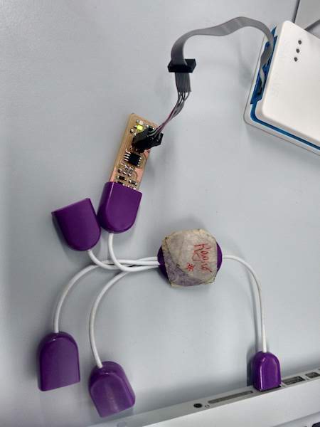
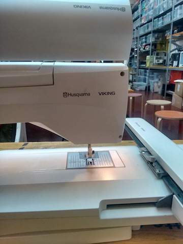
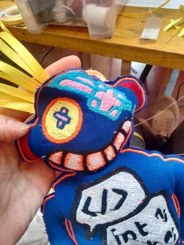
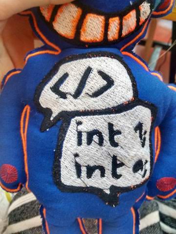
This week was focused on a free project, and the only recommendation was to try one or more digital fabrication processes not used yet in previous assignments, including computer-aided design and manufacturing. At Opendot we've decided to focus on textile design, because we've got the chance to try a particular machine that the Lab uses for workshops and laboratories with children. The output of these labs are cuties puppets made from drawings. These labs are called La Bottega dei Dotti and it's a preject made by Laura Cipriani, one of my Fabacademy 2018's colleague. Each puppet made within these labs is called "Dotti", so even our puppets are called like that, even with a first name.
This machine is an automatic embroider machine, which works with vector drawings.
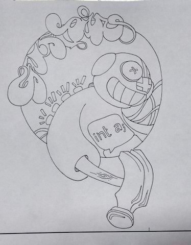
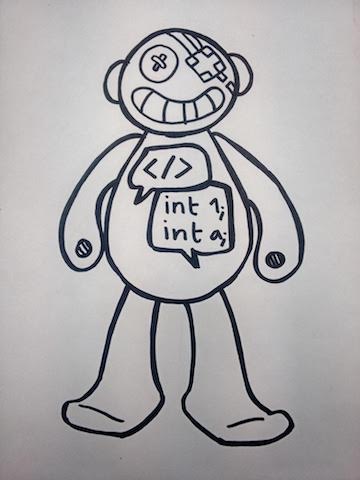
Everything starts with a sketch: you can do it on paper or directly in a 2D software for vector drawing. I've decided to do it on paper, because I miss the times when I used to draw and create illustrations. I've also imagine that my puppet is a relative of the one I'm designing for my final project, named Gustavo.
Then I've taken a photo of the sketch, in order to put it on the computer and vectorialize it (You can also scan the drawing so you will have to edit a digital file, maybe it will be more precise than a photo).
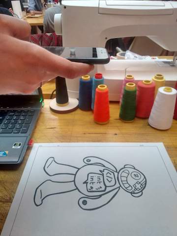
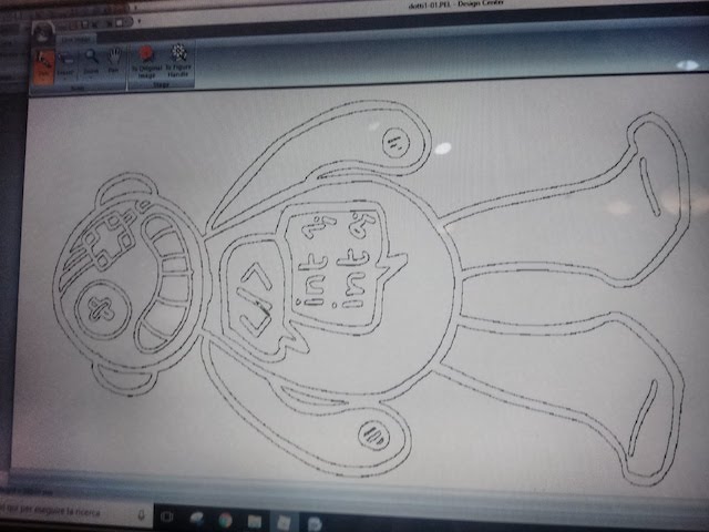
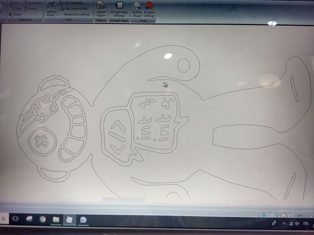
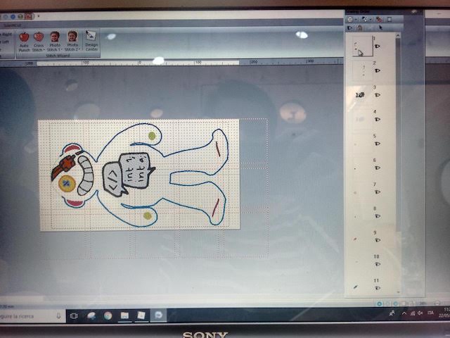
After saving the image as a .png, I've opened the software for the vectorialization, called PE Design, and import the file.
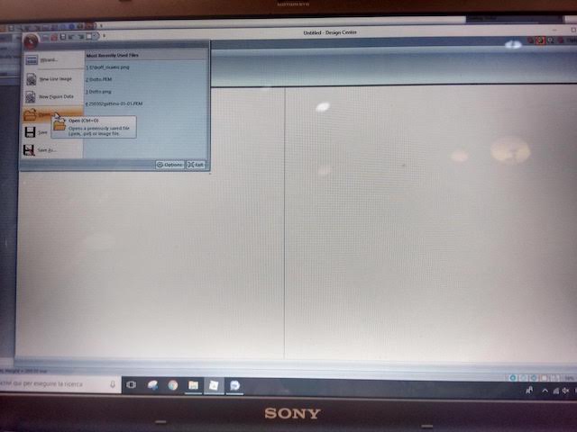
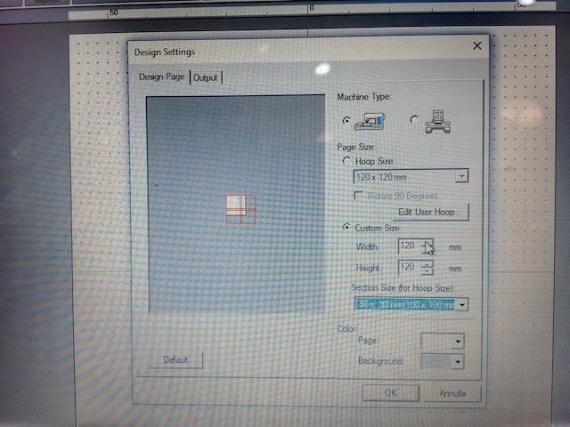
I've had to define the dimension of the loom, which is 360x200 cm.
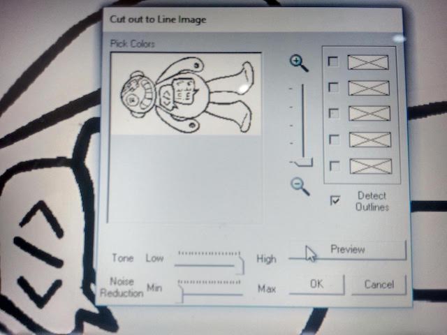
Then I've vectorialized the image, defining how many paths I've needed and some other details,
and this is the result I've obtained. Notice that the external lines have been converted into a double line, which means that also the embroidery would be double.
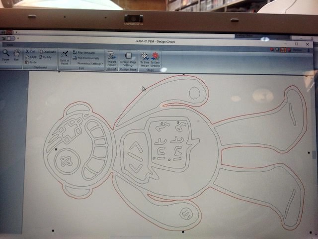
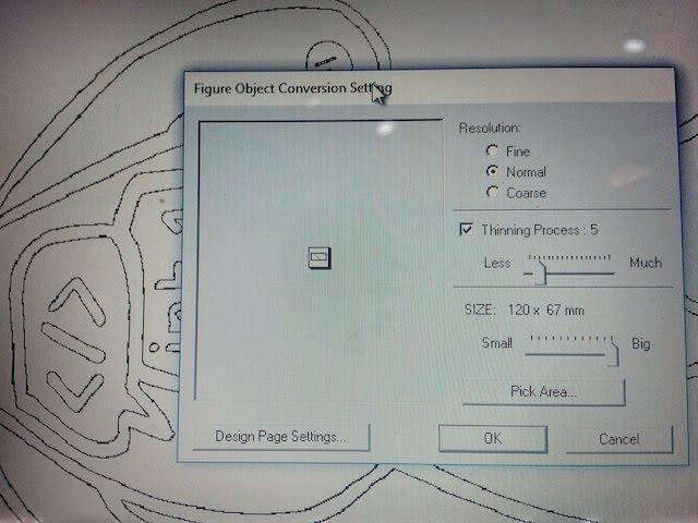
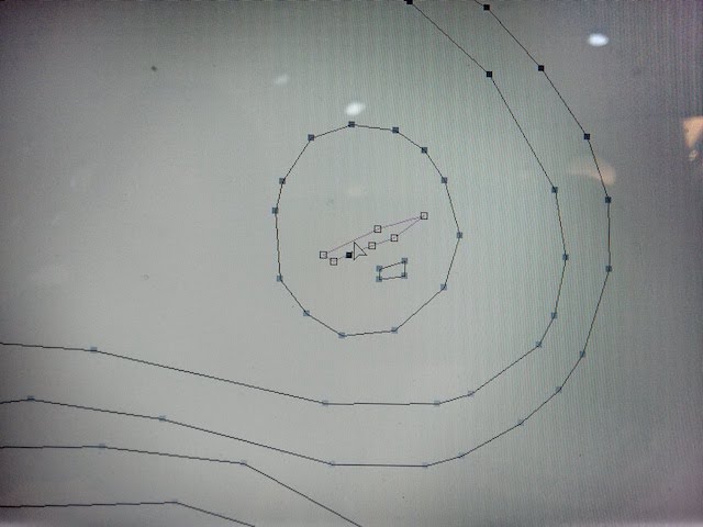
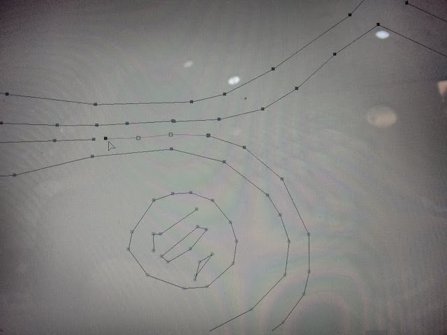
I've also adjusted some paths that could become problematic for the machine, such as points too close, open paths, etc.
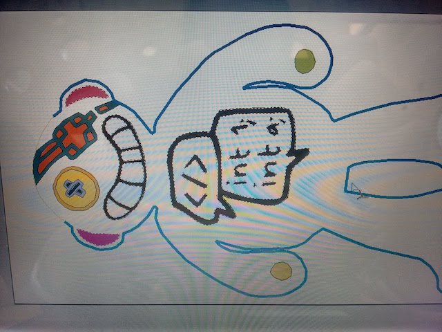
I've finally obtained a satisfying output, and it was ready for the next phase.
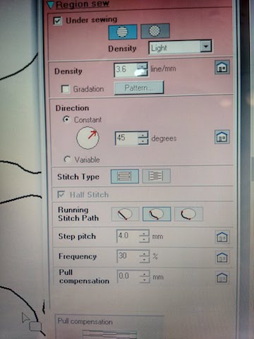
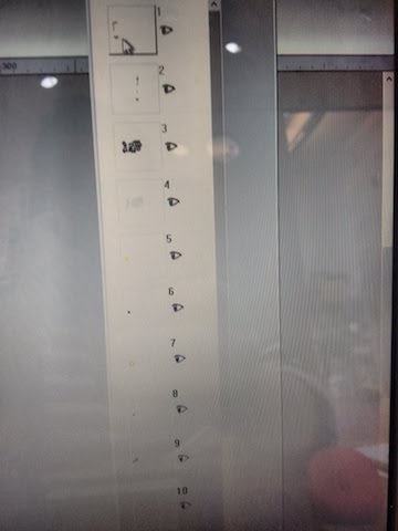
At this point you need to create the schema for the embroidery. The software offers the possibility to switch from the Design area (Line Image) to the Embroidery area (Sew Setting). You need to define first the type of sew you want for the external line:
Then you have to divide the sketch into layers, to decide the order of the sewing. To do so, the software allows you to select each line in the drawing and assign a type of stitch to it. Each line or group of lines corresponds to a layer, and you can assign a color to each of them. These colors don't necessary correspond to the color of sewing, but are mainly important to dinstinguish the various layer and change the color of the rope.
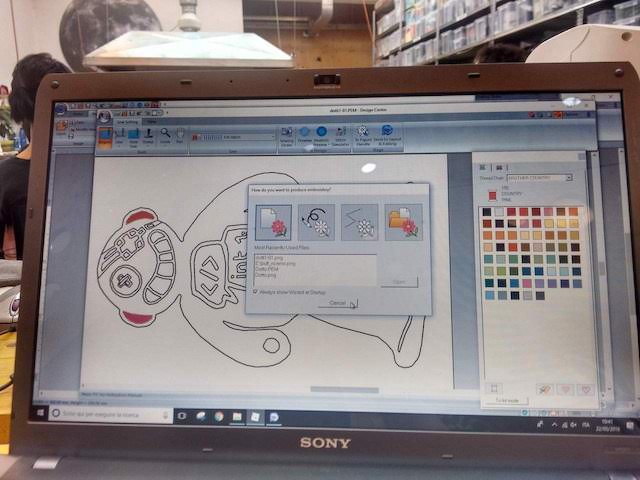
After that, on the right side you will have the list of the various layers of your output, and you can still decide the order that the machine will follow to sew the stitches.It is important to consider that it is better to start from the top to the bottom of your puppet, and group all the layers that are supposed to have the same rope's color.
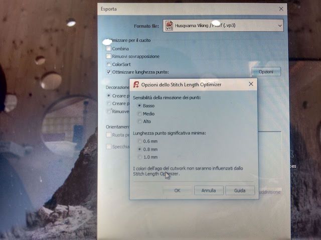
When you're satisfied with the order, you can download the file (format .HUS). But there is another operation you need to do before turning on the machine: you have to convert the file into a suitable format for the machine, because it is older than the software.
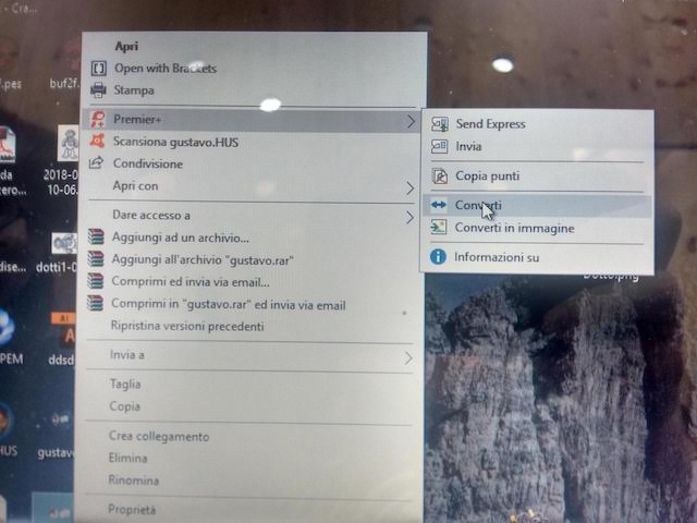
Yhe correct extension for the machine is .vp3. After that, you can put your file into USB key and insert it into the machine.
The machine will read the USB and you will have to choose the correct file, which will be shown in the small monitor. Next to the monitor there are some buttons you can use for
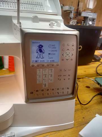
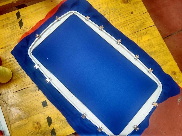
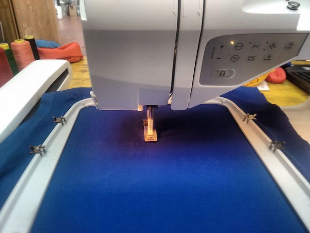
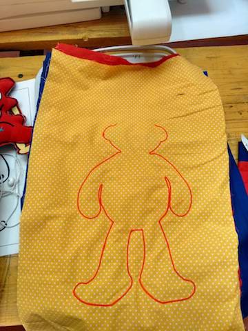
At this point you need to prepare the loom with the fabric you want ot use. Firstly, I've put the blue fabric for the front side in the loom, and a red fabric to strengthen the stitches.
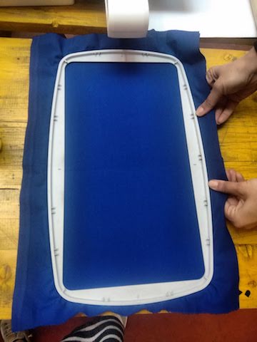
Then I've assembled the loom on the machine, paying attention to stretch the fabric on the loom in order to eliminate all the creases.
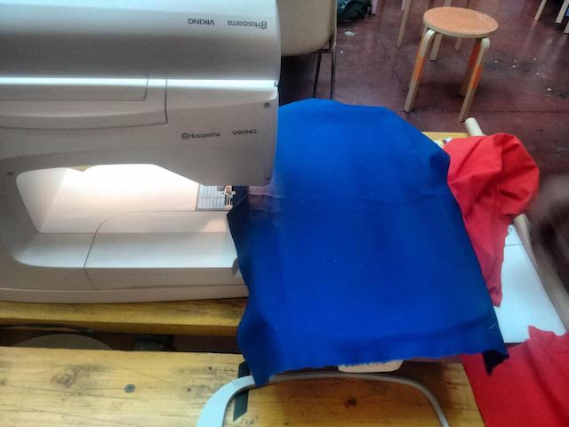
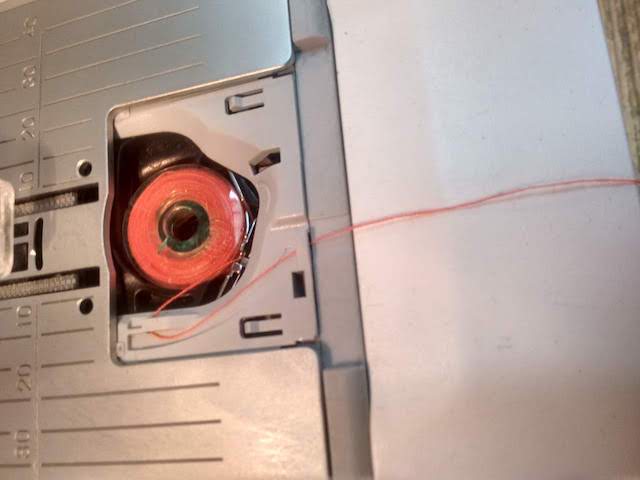
The last operation I've had to do was to prepare the reel for the thread that goes in the backside. Each puppet has indeed two sides, and the process starts from the front side: as all the sewing machines work, also this one uses a top thread and a bottom thread.
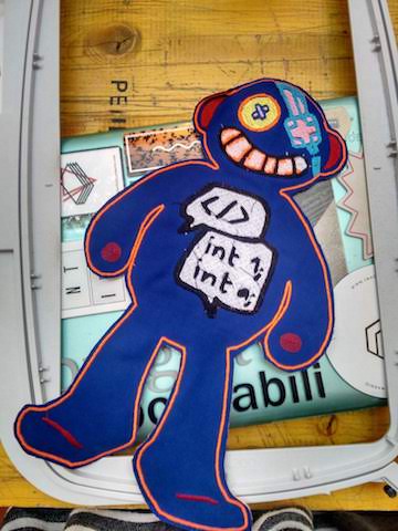
The machine was ready to start!
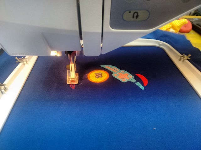
When the machine finished to sew each layer, I turned off and removed the loom. I cut away the surplus of material with small scissors, and the last phase began.
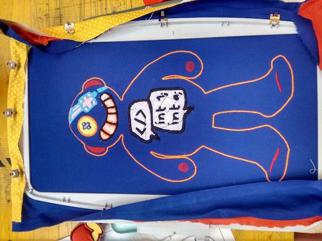
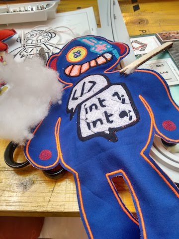
The last phase is the filling of the puppet with foam: to do so, I've used a small wooden fork to push the foam even in the most small parts of the puppet.
When I've finished to fill, I've decided to close the open hole in the head with funnny blonde hair: I cut some yellow stripes and sew each of them to both layers (front and back) in order to close the open side.
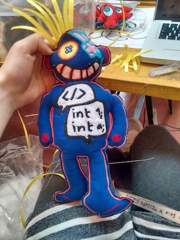
You can find all the design files here.
16 – Applications and Implications
This weeks'assignment was mainly the definition of the Final Project. We were supposed to answer a list of questions that you can find here. I've tried to answer in the most exhaustive way I could, however at this very moment there are few things I haven't decided yet. So this page will be constantly update until I'd finish the projet.
- what will it do?
- who has done what beforehand?
- what materials and components will be required?
- where will they come from?
- how much will it cost?
- what parts and systems will be made?
- what processes will be used?
- what tasks need to be completed?
- what questions need to be answered?
- what is the schedule?
It will make sounds and lights when an input will be given to it. The whole object will be used in educational contexts. It's possibile to add other inputs to the board, in order to add complexity and improve
Some fablabs have done similar projects, but also associations and schools. I've made a brief research about educational puppets, and explained it in the final project page.
The puppet will be 3D printed using PLA, because it's a safer material than ABS, so it's better in case of activities with children. Also the objects they will model will be printed in PLA: they could print them at schools. It will also have a PCB with LEDs and sound detector. The LEDs will be Neo Pixel made by Adafruit, because it's a well-developed and reliable product that could be applied to several different projects. It's also quite easy to be used, and it has a lot of available packages you can install in Arduino or other software.
PLA will be provided from schools and fablab, as a collaboration between these two realities. Other components will be provided online, and the board could be made with a milling machine in the fablab. It would also be interesting to contact factories or laboratories to search for old components they don't use anymore, and try to recycle them.
The whole project will be cost around 30/40€, because it's considered the amount of PLA, the shipping of the materials, the cost of NeoPixel, and even the developing and debugging of occasional issues. To lower the cost, instead of buying a reasy-made shield of NeoPixel, you can create your own by soldering each NeoPixel LED on the board you've designed.
There will be two parts: the electronics and the 3D model.
It will be used milling, drilling and soldering for the electronics production, 3D modeling for the puppet and 3D printing for the production. It could be also possibile to create
I still need to integrate more the two parts, for example design a smaller board to be inserted inside the puppet. Also the puppet could be designed with more holes, to help children customize it.
The biggest question at the moment is how to design a smaller board: you'll probably need to use a different tool or machine, because the milling machines have a specific tolerance, and sometimes it can't mill the tracks that are too thin.
I've planned to finish the board just in time for the presentation. But I made a mistake by not calculating the delay in the delivery of some components: I've decided to use PTH components instead of SMD, because I've just them available in short time.
17 – Invention, Intellectual Property and Business Models
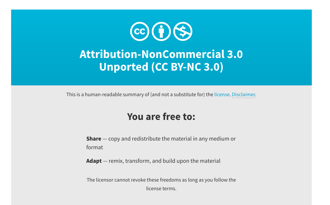
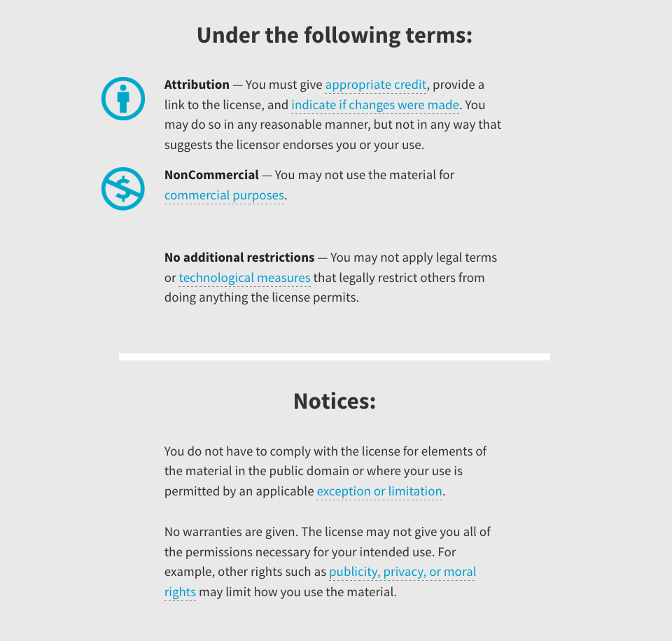
This assignment consisted in a plan for dissemination of our final project. A dissemnination plan includes also a license to protect our project. I've decided to use a Attribution-NonCommercial-ShareAlike 4.0 International (CC BY-NC-SA 4.0) Creative Commons License, because it allows (potential) future users to share and adapt the material and the project. Creative Commons is a great initiative to protect original works but at the same time to help spreading and sharing knowledges and materials among people.
For further dissemination, I've planned to put all the files and the development on a page of the FabLab Valsamoggia website, in order to let more people know about the project. I also want to create a proper website or landing page for the project, to have a sort of presentation when I'll talk with future potential users. Maybe another good idea for disemination could be creating a sort of brand identity for "gustavo", some stickers or posters or even a small flyer. This advertising material could be spread during Schools'Fairs or other events, even in small places or towns in the surroundings of our FabLab.
18 – Project Development
To check how the final project is going on, you can check the Final Project page.
When the whole project was coming to the very end, I had to answer to some questions regarding the issues raised during the process and the outcomes:
- what tasks have been completed, and what tasks remain?
I've managed to complete a satisfying 3D model, with a case for the board and an empty leg for all the cables. The board could be improved, maybe using another SMD component as micro-processor instead of a PTH one. It still remains the audio issue: I've planned to include also a shield for a micro-SD cars and an amplifier, so that users can add their own sounds and music and reproduce it, or even reproduce the audio that arrives as an input through the microphone.
- what has worked?
The design phase has worked quite well, and also the debugging: I've done the final board three times before finding the right way to produce it, and each time I've discovered something new while solving technical issues.
- what hasn't?
Time management didn't worked at all. I've started the FabAcademy two months late, and in the end I've perceived all the time I've lost because I was always in a hurry. With a better time management I'd have had more time to experiment and do the finishing work, and even design more elaborated structures. In a way I was forced to do easy and simple things by the time, because I haven't had enough to do all the things in the way I wanted to.
- what questions need to be resolved?
One of the bigger unsolved question is about the advertising: I'd have wanted to communicate better the whole project and studied a spreading strategy, maybe according to different targets. But this is a future task, I still have the chance to create a good brand identity for the project.
- what will happen when?
In the next two months I've planned to finish all the improvements of the board and the puppet; in addition to that, I want to use the logo I've made for the vynil cutting as a part of the brand identity of the project. I'll do a landing webpage to explain the project and a series of posters and postcards that can be distributed in the local area around FabLab Valsamoggia. Also, this kind of material can be brought around during School's Day or during some local fairies, to get people in contact with both the fablab and the project.
- what have you learned?
The biggest lesson I've learned is the importance of the organization and the evaluation of the available resources. I've had to learn how much time it takes to get things done, and to keep on going even if I fail. I must train myself in controlling constantly the amount of work I have to do, and to organize the resources I have. I also have to learn how to ask for help, because it's important to search for external help when you recognize you can't manage all the work to do.
So I've decided to think about a dedicated tool specifically designed to help tutors and engage pupils in teaching and learning 3D modeling and programming by directly doing them on a pre-existent item. This tool will be shaped like a funny comic character with empty holes, where children will put all the additional elements they will design and model.
final_prog from federicaselleri on Vimeo.
Inspiration
I get inspired by some projects I've seen both on the Internet and during a fair of Schools'projects. Education is a great field of experimentation for new technologies and media, and I want to give my personal and small contribute to it.
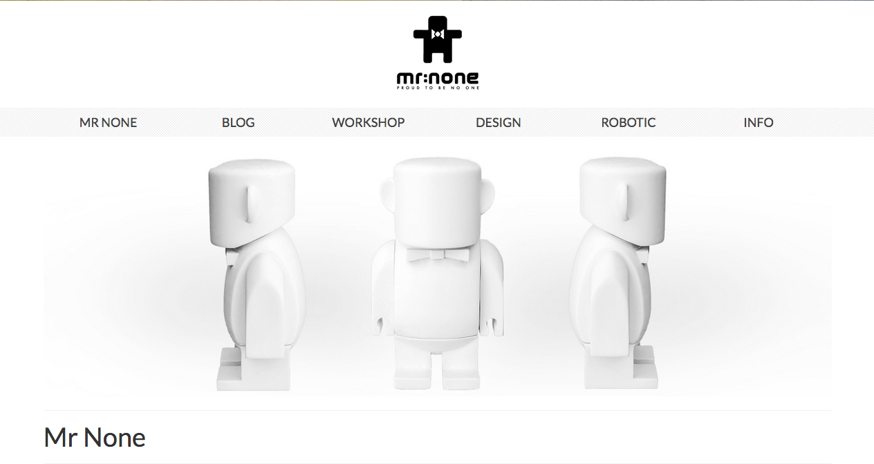
One of my favourite projects is called Mr. None. It's a project made by a FabLab near Modena, Italy, and it consists in a blank puppet that can be animated with Arduino. It is used both during lessons and laboratories outside school's schedule. It's interesting because it's really a complete project, well-designed and presented.
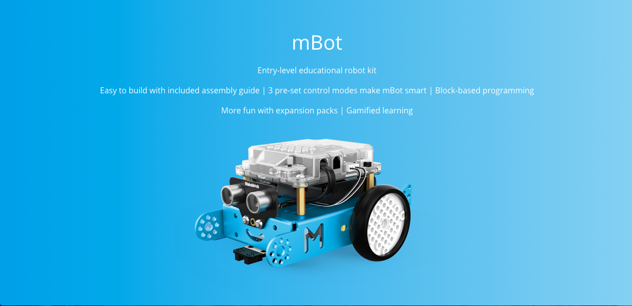
Another relevant project is mBot, an educational robot controlled by Arduino. It has various available kits and add-ons that children can build, and it is easily programmable.
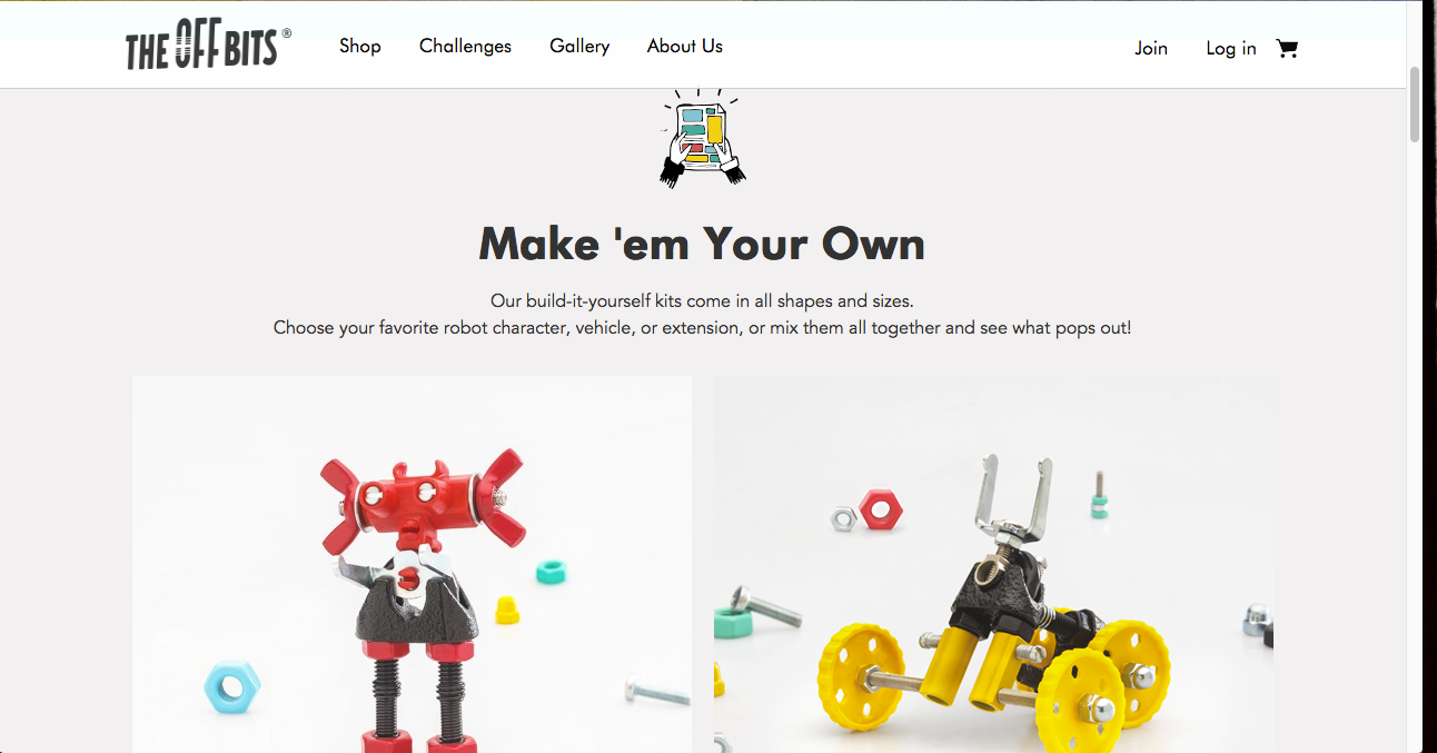
Also OffBits is a project that is focused on education. It has been developed by a start-up in Tel-Aviv, and even if it's not programmable or either electrical, it has a great idea: it is based on the reuse of the normal stuuf we all have around. It stimulates the creativity of chilidren because they can try to create their own puppet and share it to the community.
Another inspirational project I've heard about is called ScaraBot, and it's a project made by Adriano Parracciani, a teacher and digital educator active in Italy to share knowledge about new technologies in schools. Everyone can build a ScaraBot, because there is not any pre-defined kit, but it's all based on recycling and basic pieces of electronics, such as motors.
For the final board I've get inspired by the project of my Fabacademy mate Francesco Pasino, who has designed a complete board for the Machine Week. This board is quite bigger than normal boards and it has most of the components visible: for this reason I think it would be suitable for educational purpose, because it would be easier to understand what are the diverse components of a microcontroller board.
First sketches
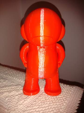
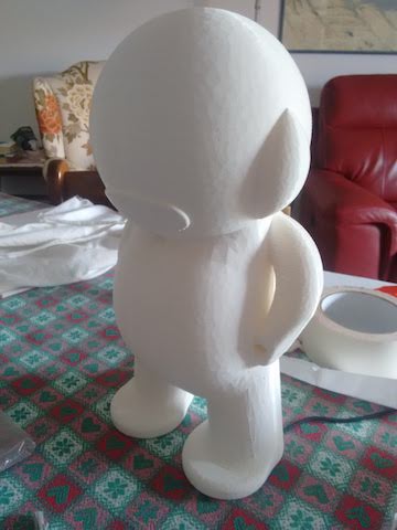
I've decided to create a blank puppet with rounded shapes, more comfortable and enjoyable to take in hands. So I've started to sketch the entire shape. At the very beginning I wanted to put the board inside the puppet, but I didn't managed to design it small enough to be placed inside.
Start modeling
To model the 3D shape, I've decided to use Fusion 360, a parametric 3D software for modeling. Since I'm not so good in 3D modeling, I've decided to use a pretty easy and intuitive software that allows me to do modeling and prepare files for milling.
I've started from sketches, made pretty in the same way as vector softwares do, with pen and points.
Then I've tried to use volumes, such as spheres, to create the head and the body.
The final prototype is this one, and I can define it as the 1.0 version.
Then I've exported the file as .STL and imported into Makerbot Print, to realize the file for the 3D printer. After that, I've printed it, it took 8 hours but here it is!
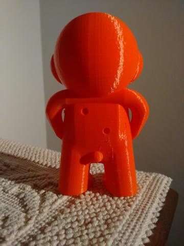
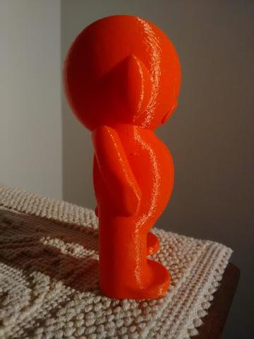
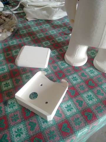
However, I've realized that these dimension (11.4cm x 5.6cm) were too small for the board, so I've decided to redesign a 2.0 version of the puppet with a case for the board on the back.
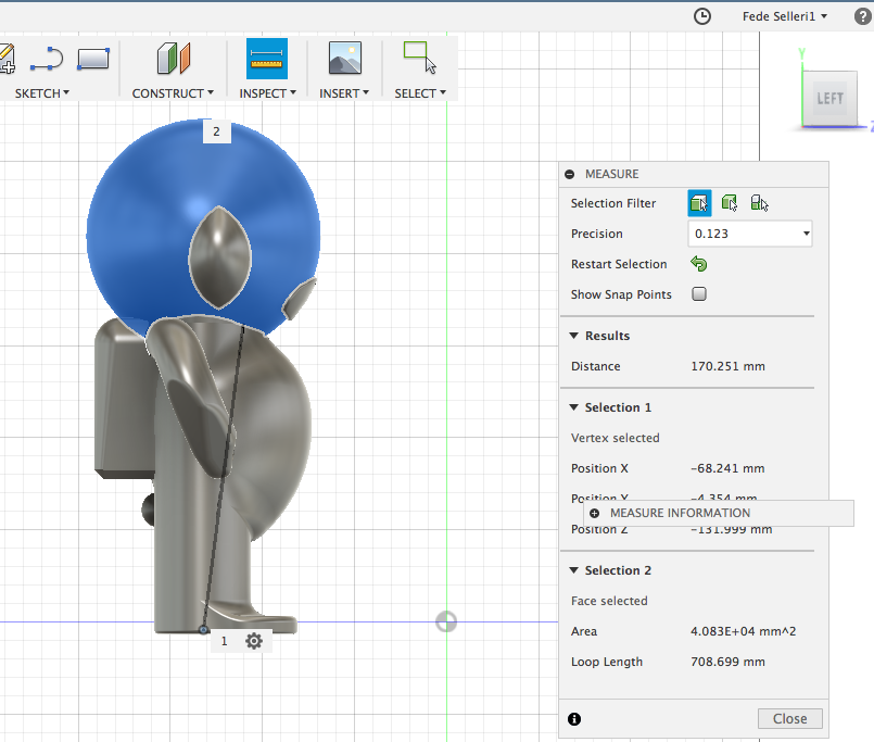
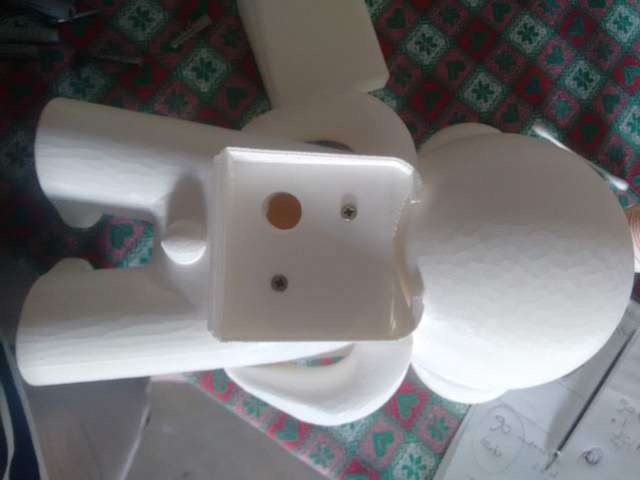
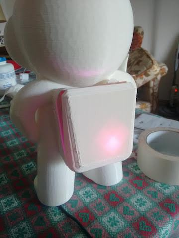
This time dimensions were bigger than the previous version, so the puppet is 23 cm tall, and the board (7x8 cm) fits perfectly on its back.
I've printed the puppet, and this time tooked a little more than the last time:
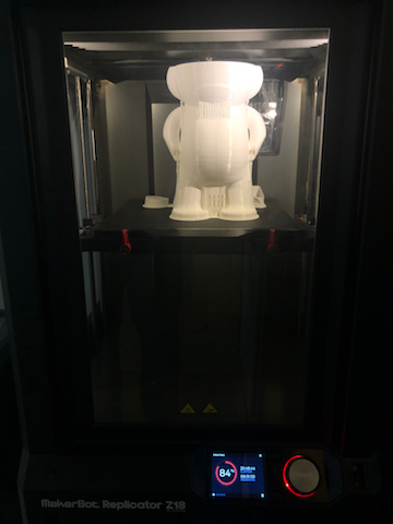
The result was satisfying:
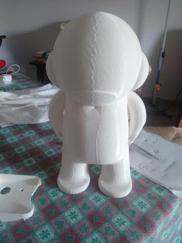
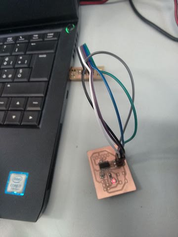
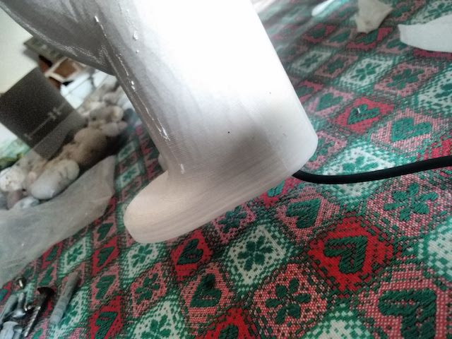
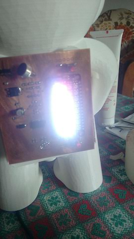
I've also placed the board inside the case, and the USB cable passed inside one leg, so you don't have wires around:
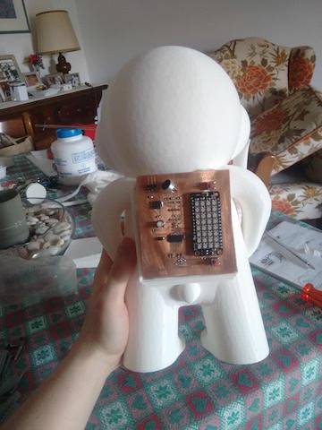
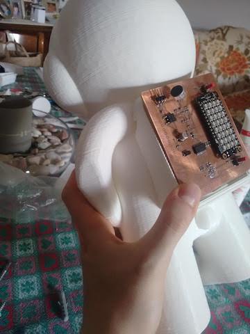
I've tried the board once again, to check if everything was working properly: I've upload a sketch from Arduino IDE, and it worked.
final5 from federicaselleri on Vimeo.
You can download the STL file here.
Electronics Design
At the very beginning I wanted to design an entire board with a lot of functions: LEDs, sound and movement sensor, amplifiers, microphone, Wi-Fi. After a long research, I've decided to use a sound detector and a LEDs matrix for the 1.0 version.
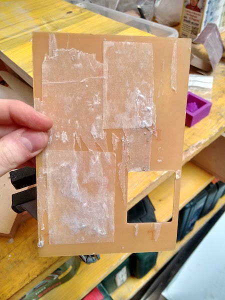
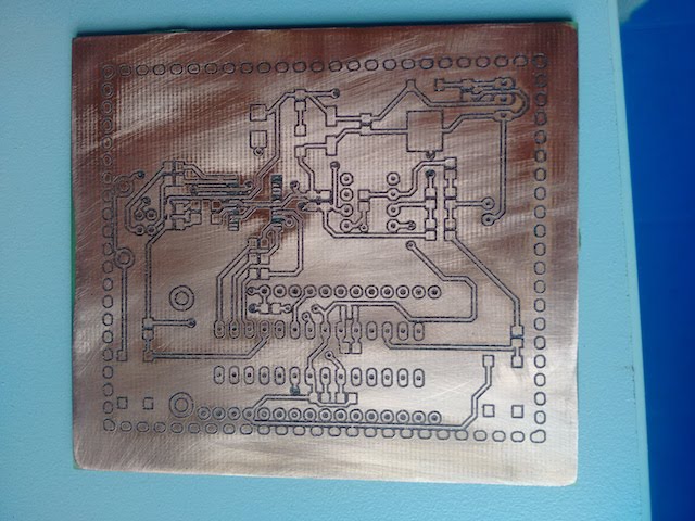
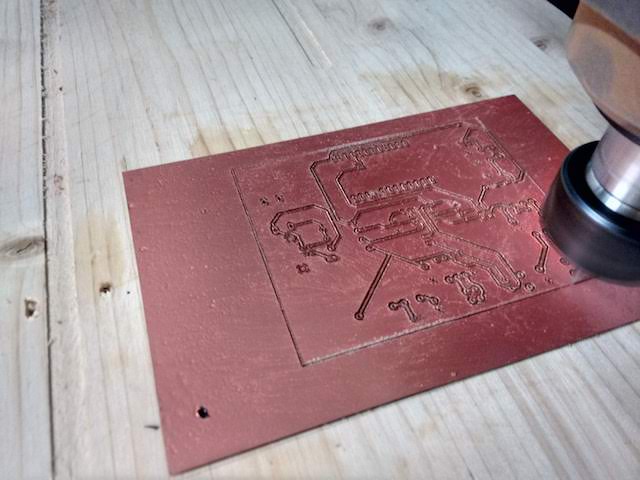
To do the PCB board, I've started to mill it at OpenDot with the Roland Mill MX-40, and then I've made other trials at FabLab Valsamoggia with a different milling machine. The first board I've designed had the traces too tiny and thin fir the bulin I was using, so I've tried to enlarge the paths:
So I've had to do a larger board, widening the traces and rearranging the components:
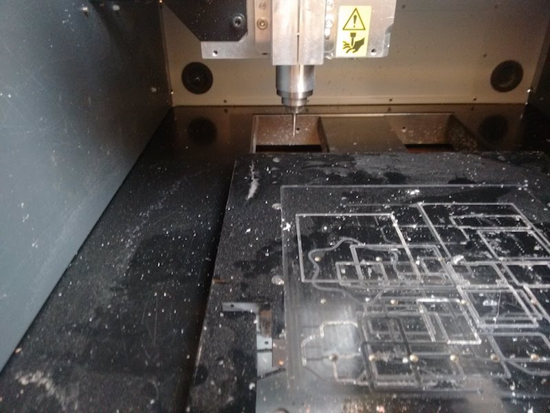
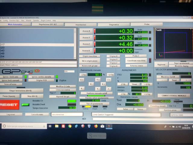
This second board has been made at FabLab Valsamoggia with a CNC machine of GP Project using Mach3Mill as CNC controlling software. This machine is entirely made by a local artisan in the surroundings of Bologna.
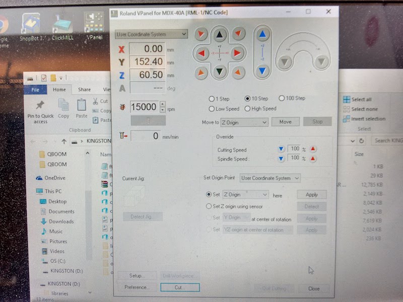
To use this machine, you need a G-Code (the file with all the coordinates the machine has to follow) and I've used Fab modules to create the G-Code file (which ends in .nc).
I've downloaded the file and loaded it in the Mach3Mill software. The interface looks like that:
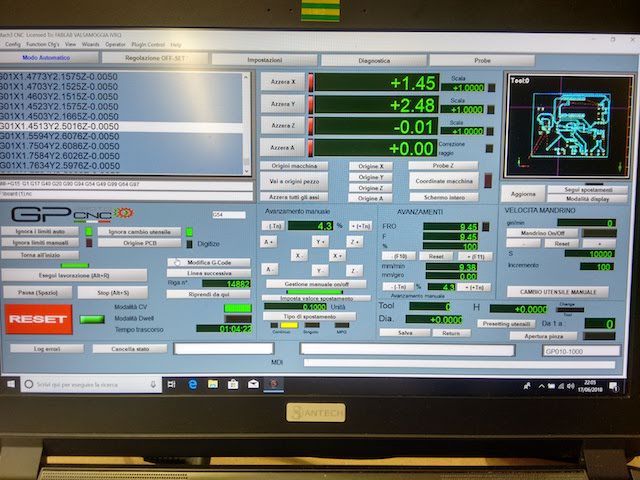
You have to firstly load the g-code, then you can set the X,Y and Z of the tool.
I started with the first trial:
final from federicaselleri on Vimeo.
Then a second one, because I've discovered some errors in the board and redesigned it.
final2 from federicaselleri on Vimeo.
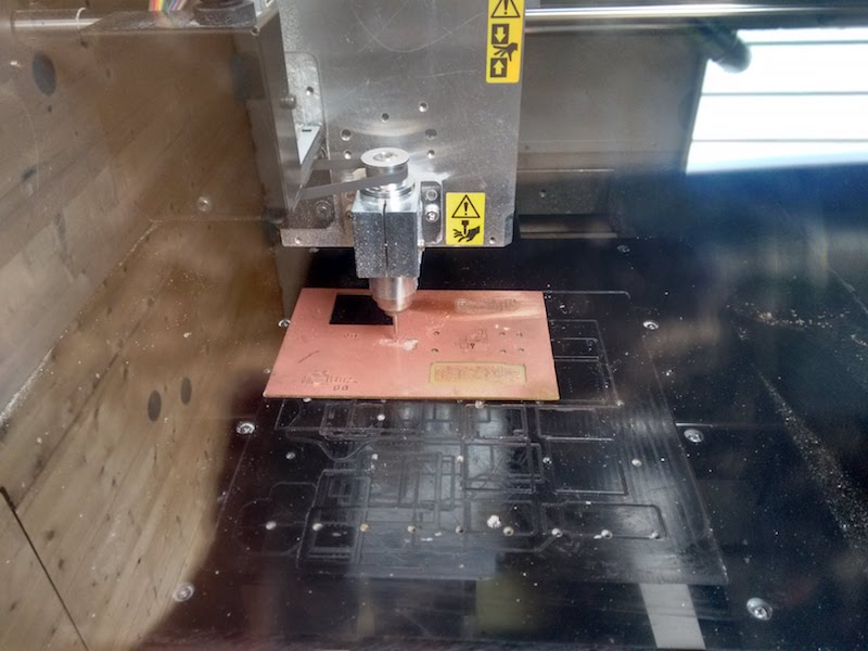
This machine can't mill tracks that are too thin, so I've decided to have a bigger board with clear paths. Initially I've planned to use standard SMD components, but due to some issues in the delivery I was almost forced to use PTH components. So I've also drilled all the holes for the components.
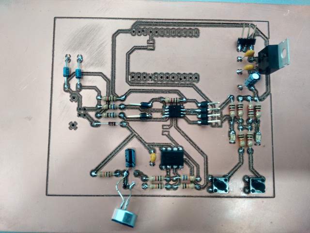
After that, the board was ready to be soldered:
Then it started the tragic part: programming the board. I've tried again to Atmel Ice, but it didn't worked at all. So I've used the FabTinyISP, and it worked! I've used a PC with Linux/Windows, because the process on MacOS is quite difficult (due to the low openness of the system). I've used micronucleos to create the firmware for my board, following this tutorial.
Unfortunately, when I've tried to plug the board directly on the computer and upload the code via Arduino IDE, it simply didn't upload anything. So I've to keep trying to make it working!
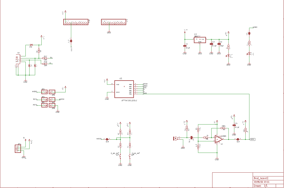
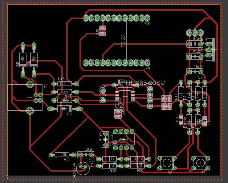
After the Final Presentation, I've decided to improve the board and redesign it, to have a simpler structure easier to program. This is the result after the redesign:
And here's its schematic:
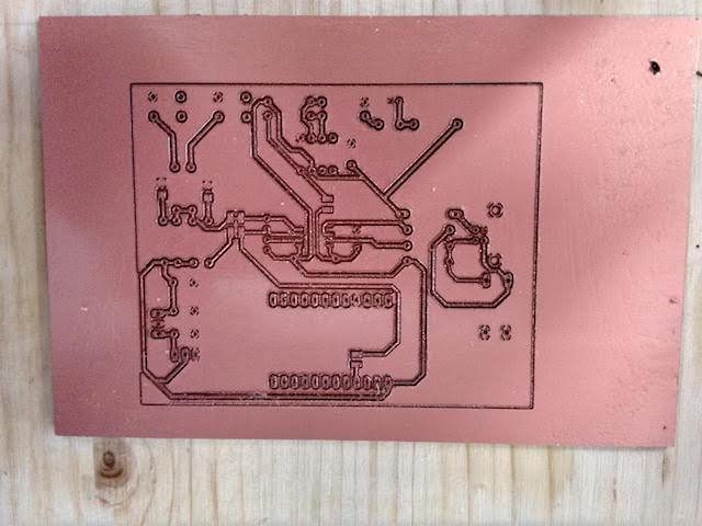
I've also milled the board, and this time it took more or less 1 hour to mill and cut the board.
You can download the PNG files from here.
The soldering phase was not so difficult, but I've had to make some drills for cables on the bottom level.
I've discovered that ATtiny45 hasn't enough memory for my intent, so I've decided to use ATmega328, which has much more memory. The rest of the components has been remained the same:
- 4x 100 nF capacitor
- 4x 0.1 µF capacitor
- 1x 10 µF capacitor
- 1x 22 uF polarized capacitor
- 1x SMB Diode
- 1x USB type-B
- 1x ATmega328
- 1x Positive Voltage Regulator
- 1x 1x3 PIN header
- 1x NeoPixel FeatherWing 4x8
- 2x 68R Resistor
- 2x 330R Resistor
- 6x 1K Resistor
- 3x 10K Resistor
- 1x 100K Resistor
- 1x 1M Resistor
- 2x Switch SMD
- 1x Omni-directional electret microphone
- 1x LM386 Low Voltage Audio Power AMplifier
- 1x BERG USB connector
- 1x Resonator 16MHZ
I've programmed it to be used with Arduino IDE, without FabTinyISP. You can see the complete process here, for the Embedded Programming assignment.
You can download the schematic and the board file here.
Interface
I've design a interface to control the colors of the NeoPixel. I've decided to use Processing to create a dynamic interface. I've reused the same library as for the Machine assignment, the ControlP5, and a sketch named ColorPicker. I've created a "picker" for each LED, so you can control the color once the board is turned on.
To connect Processing with Arduino IDE you need to open a "Serial Port", by simply importing the serial library on Processing and creating a Serial Port:
I've also created a Color Picker for each LED as a variable, and then used them to create the visual Picker:
I've set the position (X,Y) of each picker, and the range of colors I wanted to have. Then I've created an ellipse of each picker, to show better the chosen colors and help the users to decide which color use and in which position.
Then I've used a function for each picker to send the input to the serial port connected with the board. Processing will send the RGBA values for each picker.
Here it's how it looks like with the first 9 pickers, you can see that by controlling each of them a message is printed in the serial monitor of Processing.
Future planning
I've planned to do a 2.0 version of the kit, with more integration among electronics and 3D modeling. I want to insert the board inside the puppet, and add more buttons to control audio and lights. I also planned to add an amplifier and a shield for micro-SD card, in order to add music. I want that users have the possibility to upload their own music and sounds and play them.
As you can see also in Applications and Implications assignment, I've decided to use a Creative Commons License to protect my work. In particular, I've chosen the "Attribution-NonCommercial-ShareAlike", which allows users to reuse and improve a project: "This license lets others remix, tweak, and build upon your work non-commercially, as long as they credit you and license their new creations under the identical terms." (from Creative Commons website.)