Fab Academy 2018

@ Opendot, Milan

"Machine design: how it works"

video machine OPENDOT from lauracip on Vimeo.

LINK HERE

Shoot a ball (Polar Machine) and hit the basket (Cartesian Omniwheel Robot) - MAKING OF from Opendot students on Vimeo.

LINK HERE

FINAL RESULT

Our team

In this project, we are a group of seven students: six at Opendot, Milan, and one student at Crunch Lab, San Dona’ di Piave (VE).

Brainstorming and team building

Last week, we met at Opendot and talked together about a machine which does something, and in its parts can be useful to our individual final projects. We thought of a ping pong ball shooter to a moving target., and after a brainstorming, we chose to built two machines:

We are very excited! It is almost four months we study and practice together and we feel a team. We understand it is a great deal of complexity and a new adventure to be lived together.

Inspiration

Some of us love soccer, and were fascinated by a professional ball shot machine like the Globus EuroGoal one. Some others love robots, so they thought that the target could be a basket fixed on a remote-controlled mobile robot.

What’s it

Our project is made of two small educational machines, not just related to learning how digital and electronic fabrication techniques work, but also useful within interdisciplinary educational paths, especially regarding STEM subjects such as physics, We imagine that it could turn into an adaptable and perfectly suitable tool for both playful and educational use, and according to the level of complexity it could be useful for a wide range of purposes.

The interaction between the two machines could be implemented and their versatility lies also in this aspect: balls shooter and omniwheels can work as separate systems or can be connected to create various different educational dynamics.

Scenarios

By integrating some movement control systems and verification rulers, the ball-shooter can stand as a live experiment to understand and learn the theories of aerodynamic: evaluation of the gunshot, speed, gravity… The interface can become more playful or education-oriented, according to the needs of the user: more control on adjustment, data visualization, launch simulation, etc.

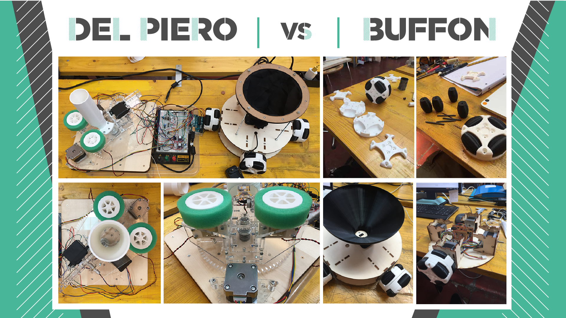
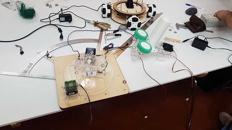
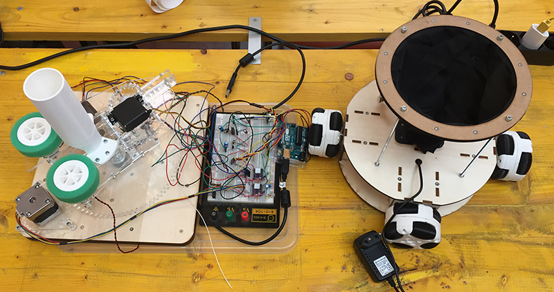
"Shoot a ball (Polar Machine) and hit the basket(Cartesian Omniwheel Robot)"

FIRST WEEK

Parts of the platform shoots balls:

  • * orientation platform: rotate along the z axis (stepper + potentiometer + bluethoot module)
  • * riser: (1 stepper + a potentiometer) rotates along the x axis
  • * launch pad: has a servo motor to launch the ball and two DC motors to run the discs continuously
  • Parts of the robot catches/dodges balls:

  • * Omniwheels: can be driven with full force, but will also slide laterally with great ease
  • * body with motors (4 stepper connected 2-2, board with 2 driver for stepper, optical sensor, -programming in GRBL -in progress-)
  • * target (T.B.D.) / basket: 3d printer basket making by spiral printer mode
  • 3d models | platform

    3d models | robot

    making of | platform

    making of | platform: video

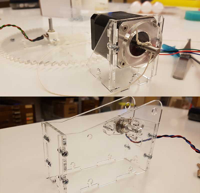
    machine design: launch pad test

    making of | robot

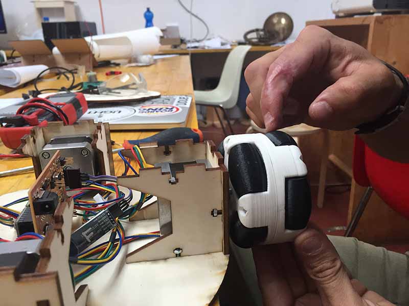
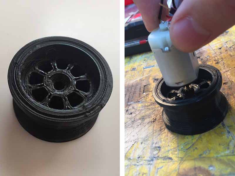
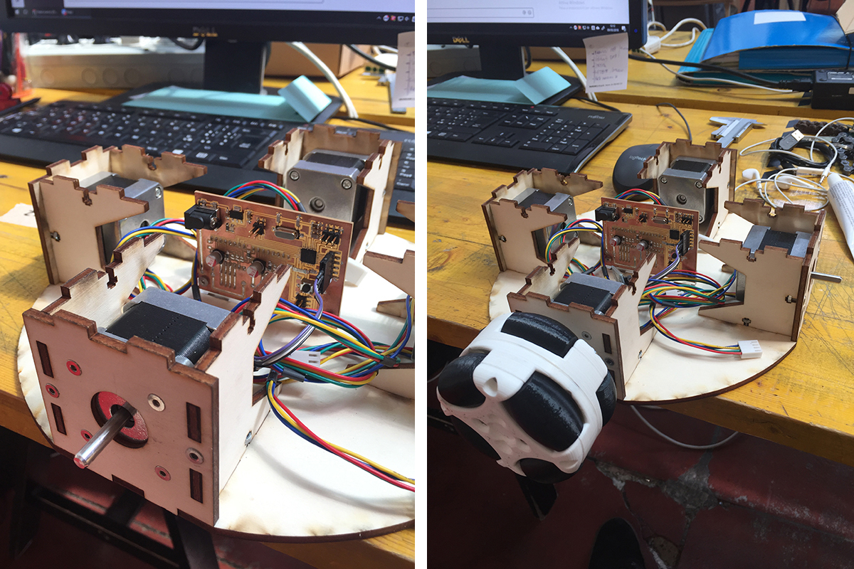
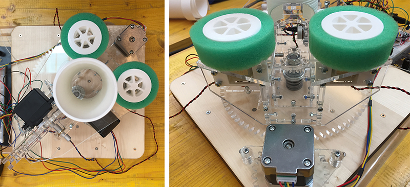
    Omniwheels is being assembled with 3D printed wheels, support sides laser cutted and Stepper motors.

    SECOND WEEK

    Robot: evolution

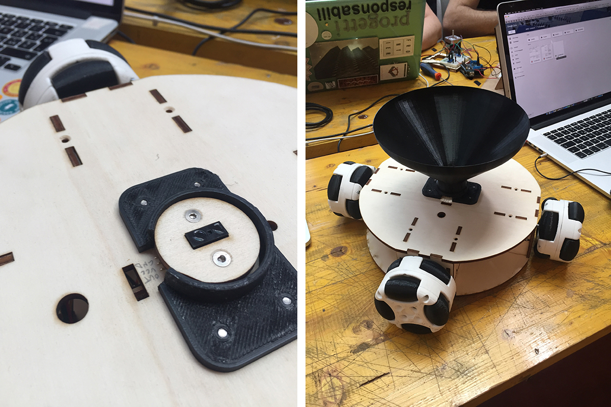
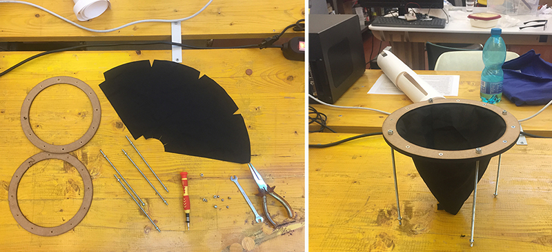
    The second part of the design of a CNC machine consists of a mobile basket. The basket can move in all directions thanks to four omnidirectional wheels controlled by a card programmed with a GRBL firmware. Above the central body a cone-shaped basket has been mounted. Through the interface you can decide the position and the speed of the basket.

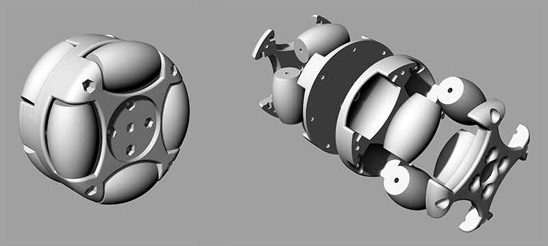
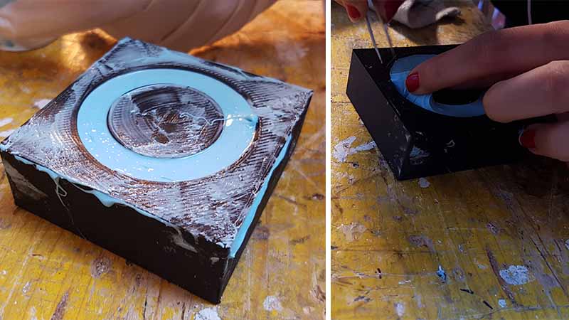
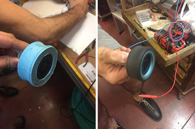
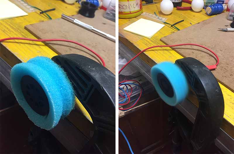
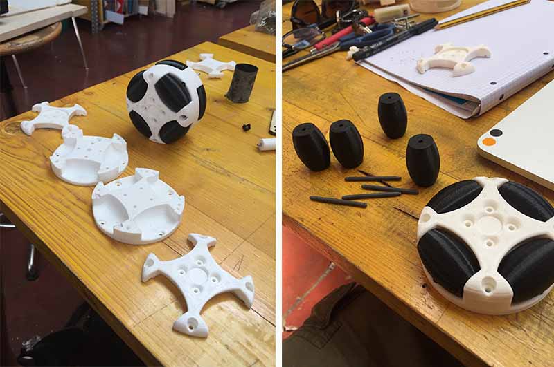
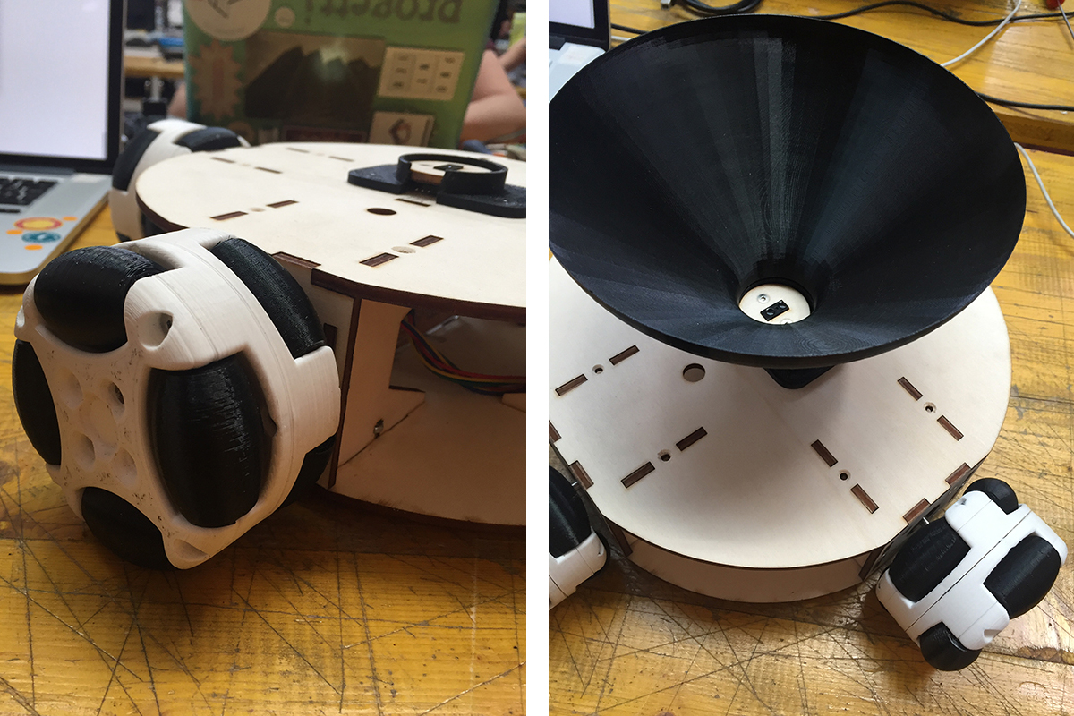
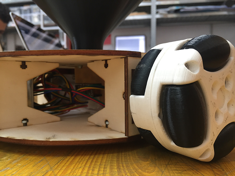
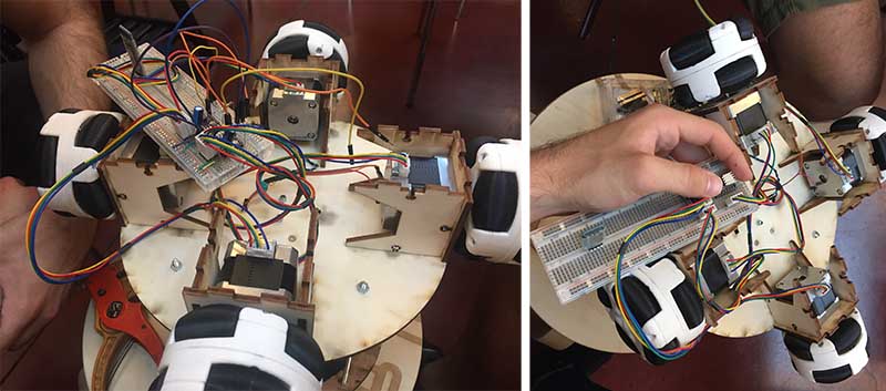
    OMNIWHEELS: the wheels were made by downloading an example from thingiverse.com (https://www.thingiverse.com/thing:1464755) and modified slightly. The wheels were made with the 3D printer in all its parts. Each wheel is made up of eight smaller wheels that allow its transverse movement and 4 elements that close the smaller wheels in a sandwich. Each wheel is connected to a stepper motor. The opposite wheels move in the same direction, so they do not allow the robot to turn around its central axis.

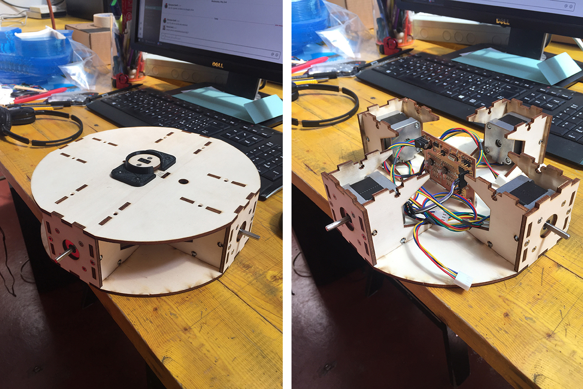
    BODY: it was made of laser-cutted plywood.

    BOARD: with regard to the movement of the card has been programmed with a firmware grbl, similar to those of the modified numerically controlled milling machines, to control the interaction of the wheels to enable it to move in a known position. An infrared sensor has been connected to the card to detect the presence of the ball. The communication takes place via bluetooth and an interface through which you can adjust the speed of movement, decide on the size of the playing field and the position of the robot within the field. Inside the interface there is a button to confirm the position of the robot and to start the movement. Finally, the stat button changes color if the infrared sensor is activated.

    BASKET: the basket has a height and a diameter of 16cm, is composed of a double circle in plywood which is supported by 4 threaded bars. The ball is directed towards the infrared sensor thanks to a fabric cone fixed at the top between the two plywood circles, and at the bottom by a ring obtained with 3D printing.

  • 3D PRINT wheels, infrared support, basket ring
  • LASERCUT central body, basket ring
  • ELECTRONIC DESIGN board
  • ELECTRONIC PRODUCTION board
  • INTERFACE processing
  • PROGRAMMING grbl
  • COMMUNICATION bluetooth
  • INPUT infrared
  • OUTPUT stepper motor
  • Ping pong ball shooter: evolution

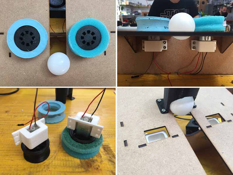
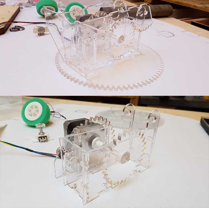
    Three are the parts of the ping pong ball shooter

  • BOTTOM : It is composed of a CNC router machining plywood board.
  • CENTRAL : On the board are fixed two meshing 3mm laser cut plexiglass gears (a) and (b). They transmit a rotational motion, thanks to a stepper motor fixed at the center of the external smaller gear (a), and a machine fixed on the top of the central larger gear (b), and located in a plexiglass box.
    The central larger gear, is a support to two movements of the ball schooter: a horizontal movement from 0 to 120 °C At the center of the gear and the box, a central pin is fixed on the plywood board. It has two ball bearings, overlaid by a plexiglass gear (c).This one is meshed with a smaller gear (d), fixed on a side potentiometer. The meshing gears (c) and (d) are constrained by the central pin, nut against nut. In the meshing movement, the smaller gear (d) turns, following the 0 to 270°C rotation of the potentiometer, around the meshing gear (c) which allows the 0 to 120°C rotation of the larger gear (b).

    A vertical movement from 0 to 60°C of the top part of the ball shooter. This part is fixed on the above box through an axis, which supports the elevation gears, and passes through both top lengths of the box.
    On one top length of the box, two meshing gears are fixed: a larger portion of gear on the extremity of the axis, screwed under the launch pad, a smaller meshing gear connected to a potentiometer with a rotation from 0 to 270°C.
    On the opposite length side of the box, a stepper motor, fixed on a plexiglass support screwed to the bottom gear (b), passes through the second plexiglass support of the launch pad. Around its axis, is fixed a tight rope tied to the back of this support. When the stepper motor runs, the tight rope helps the launch pad to rise from 0 to 60°C, thanks to the opposite meshing gears which are helped by the potentiometer in its 0 to 270°C rotation.
  • TOP : the launch pad.
    It is made in 4 mm laser cut plexiglass. It receives four parts: three on its top
  • MIDDLE: a 3d printed tube used as a ball loader, fixed on the pad, and open at its bottom to let each ping pong ball passing through.
  • FRONT: The discs are composed of two parts: a 3d printed wheel and a sponge gasket. Each disc is fixed on a small 6V DC motor located under the pad. When the motors are rotating, the discs drive the ping pong ball to be launched.
  • BACK : a fixed plexiglass rack and pinion animation The rack and pinion act as a type of linear actuator that comprises a pair of plexiglas gears which convert rotational motion of the HS 422 servo motor into linear motion.The linear gear bar called the rack pushes the falling ball from the open base of the ball loader straight over a distance of 6.5 cm through both discs ahead. Thanks to the speed of rotation of the discs, the ball is propelled out of the launch pad.
  • One under its top, vertical to the launch pad: a fixed plexiglas vertical board (front of the ball shooter) on which two 3D printed motor supports are fixed. They hold the two 6V DC motors actioning the discs.
  • Debugging

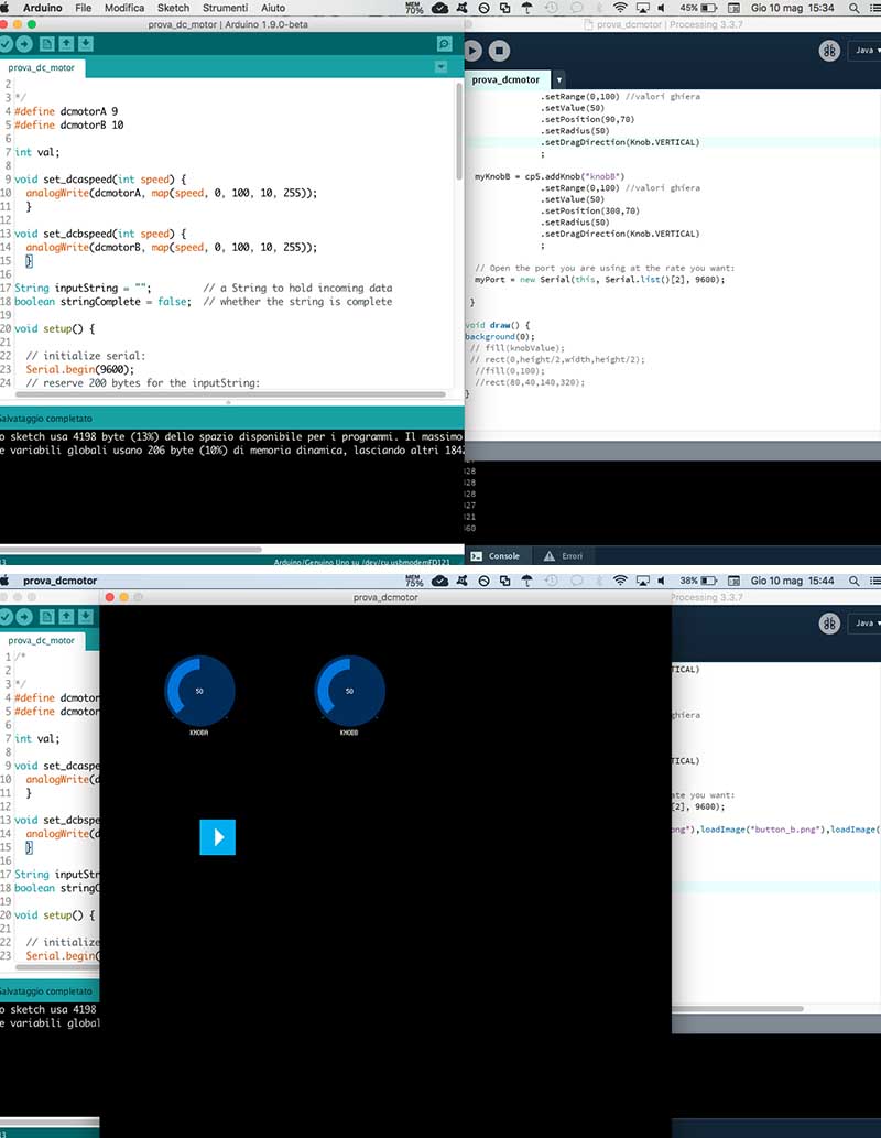
    our board has stopped working, the day before the review! we are trying to replace it with an arduino!

    INTERFACE OF PING PONG BALL SHOOTER:

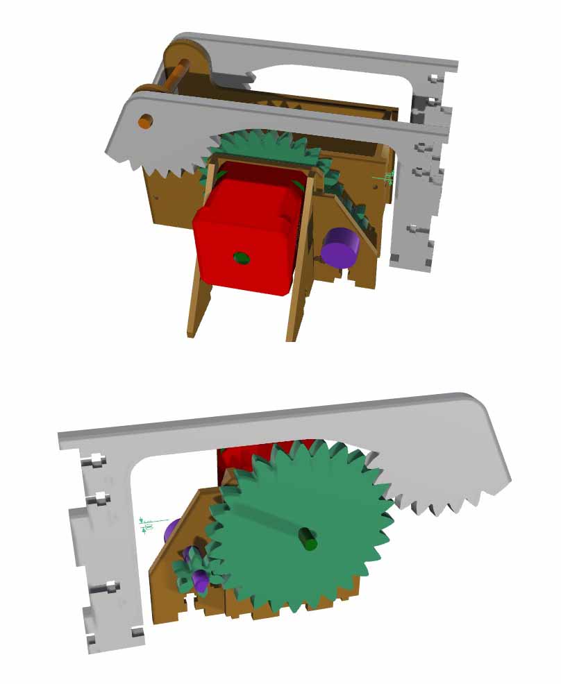
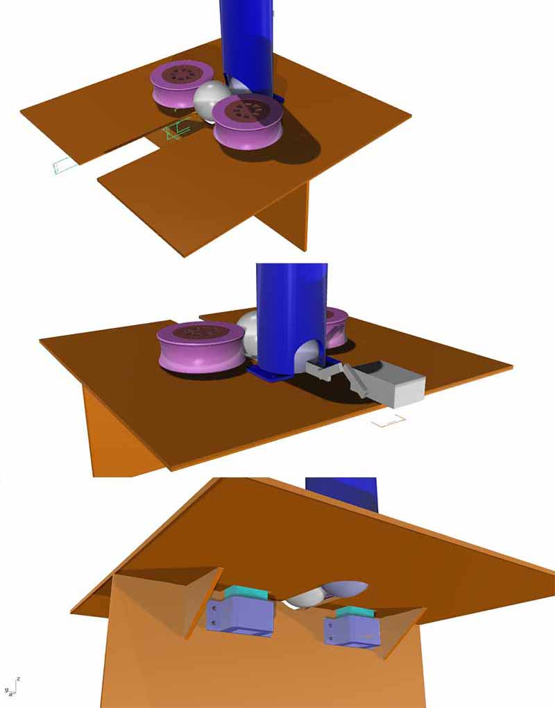
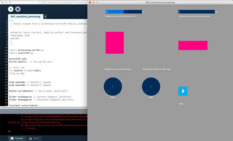
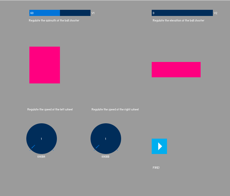
    The shooter interface is divided into 3 parts: the first part is used to manage the two movements of the launch pad: the rotation and the azimuth. The cursors are used to better manage the movement and the rectangular shapes help to perceive the movement that the machine is doing. The angles of movement correspond to those of the machine or from 0 to 120 for rotation, from 0 to 60 for the lift. In the second part you can manage the speed of the discs separately, we have chosen sliders that resemble a tachometer: to control the throw and the speen shoot of the ping pong ball.

    INTERFACE ROBOT:

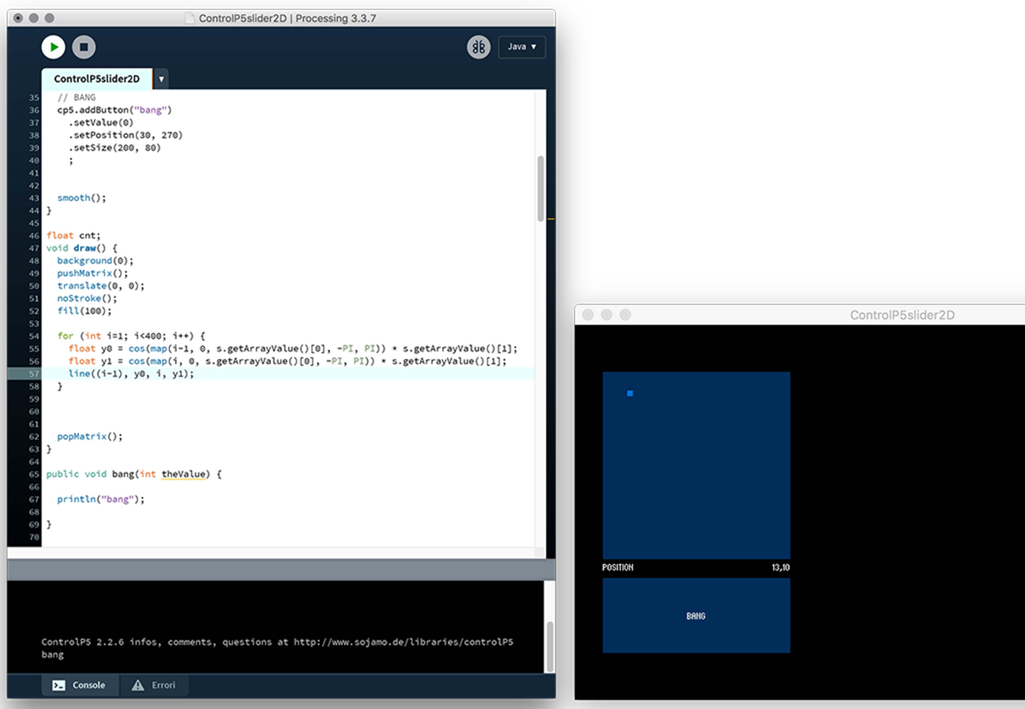
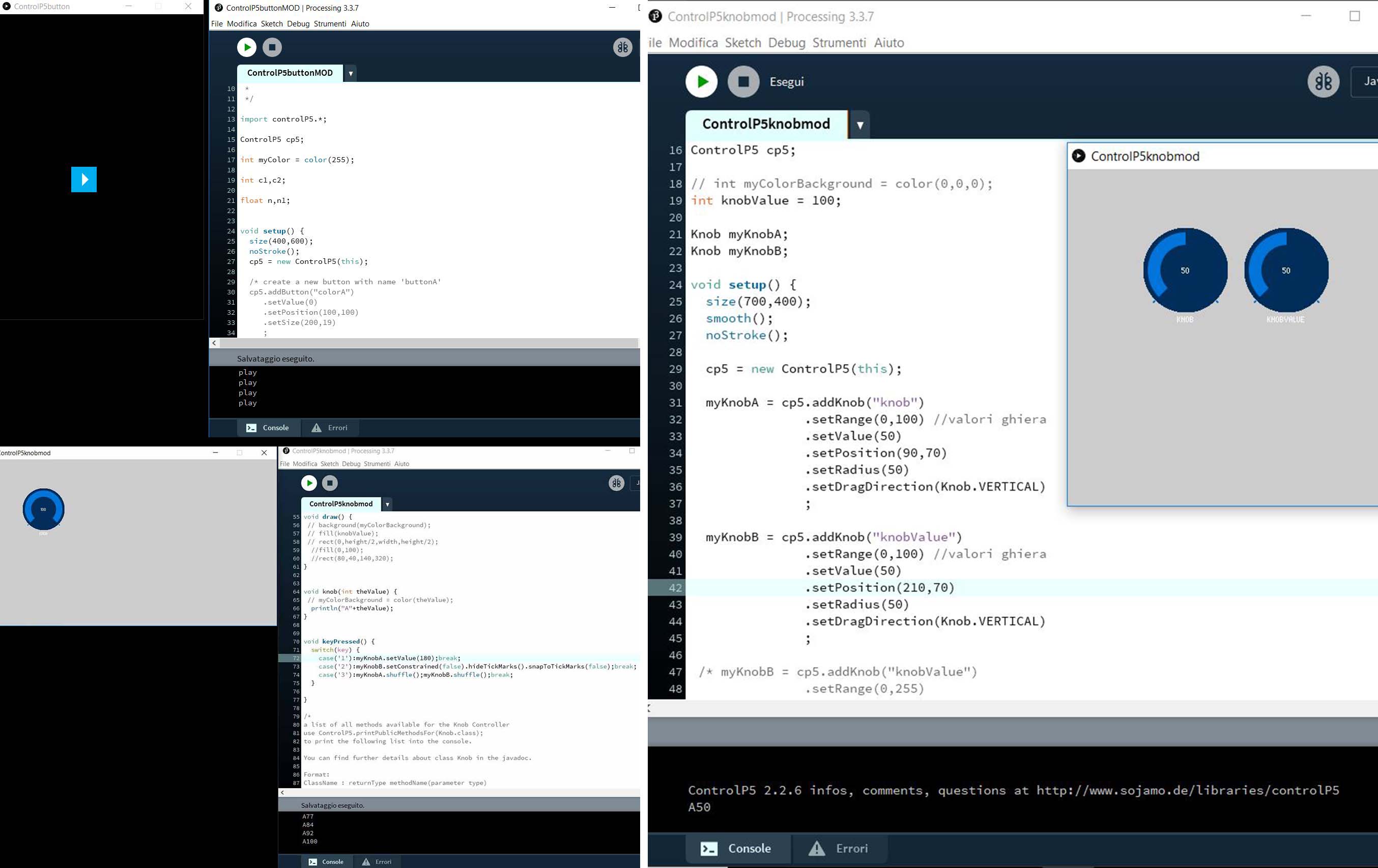
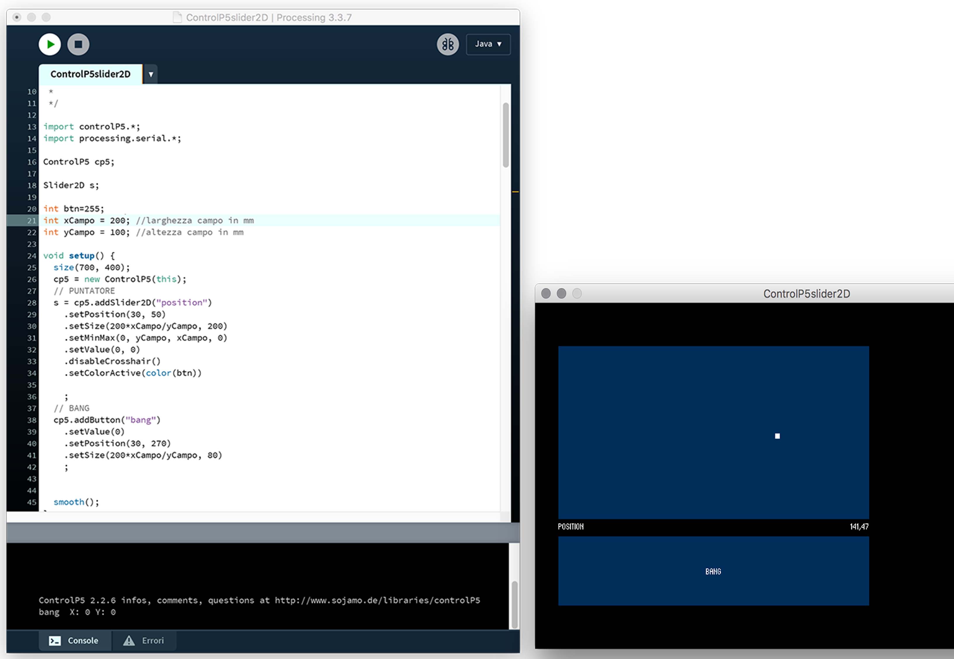
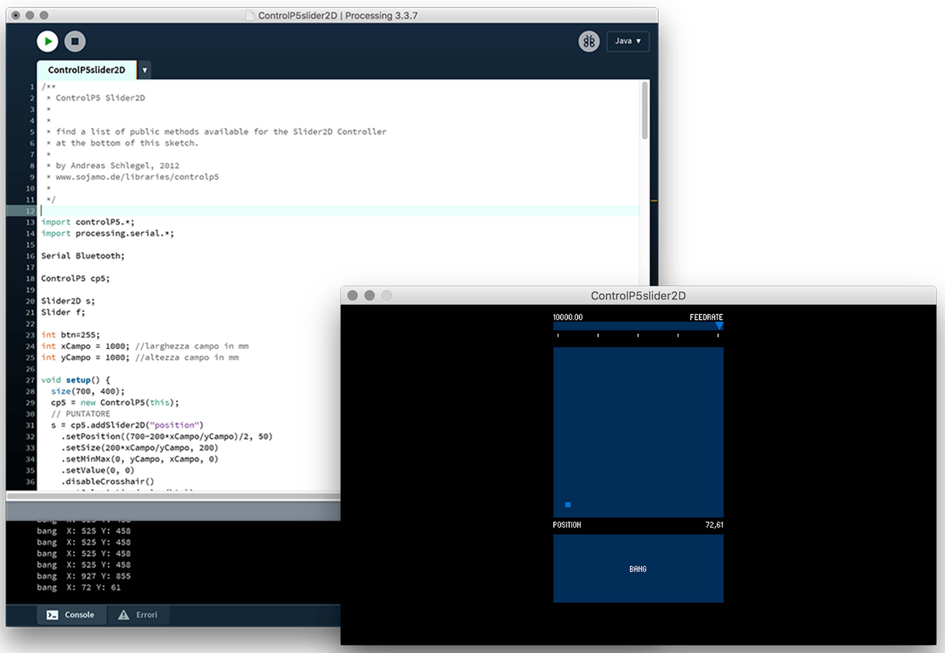
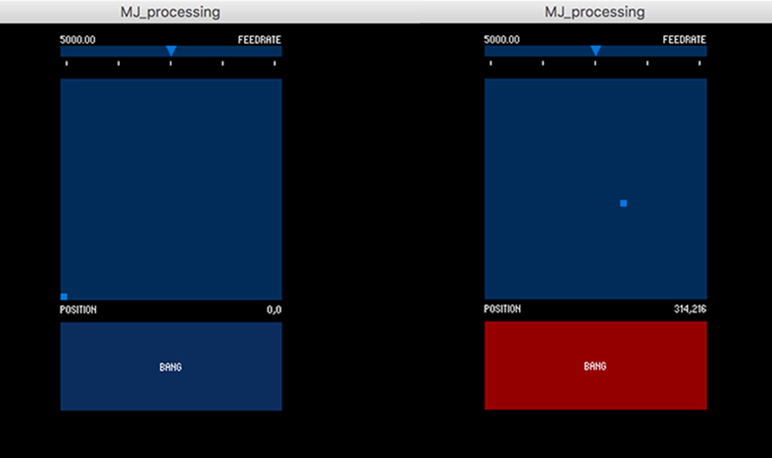
    After connecting the robot to the power supply and connected via bluetooth to the PC, you can open the interface on Processing and start playing. Before starting the interface program, enter the dimensions (in millimeters) of the playing field. As soon as the PC and the robot are put into communication and the field size has been declared, the robot is in position 0,0 of the field, ie in the lower left corner. Through the interface window, in addition to the position, the movement speed can be established via a scroll bar at the top. The field is represented by a rectangle that will have the (proportionate) dimensions of the real field of play. Inside the field the robot is represented by a small square that can be moved with the mouse pointer.

    At the bottom of the interface window is the robot's start button and moves it to the position in the field we have just chosen. Finally, the start button changes color if the ball activates the infrared sensor positioned on the bottom of the basket.

    DOWNLOAD AREA ROBOT:


    DOWNLOAD AREA SHOOTER:


    Instructor

    Contacts