Assignment
- Measure something
- Add a sensor to a microcontroller board that you have designed and read it
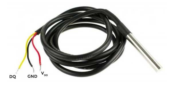
For this assignment i’ll be using the DS18B20 submersible digital thermometer. The full characteristics can be found in the datasheet. Here are the main characteristics:
- 9-bit to 12-bit Celsius temperature measurements.
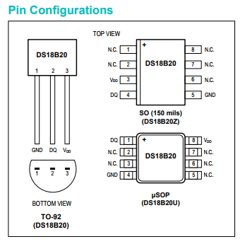
- Available in 8-Pin SO (150 mils), 8-Pin μSOP, and 3-Pin TO-92 packages. Figure 2
- Alarm function with nonvolatile user-programmable upper and lower trigger points
- 1-Wire bus that by definition requires only one data line (multiple sensors can be attached to the same port pin, each has a unique 64-bit serial code sorted in onboard ROM)
- Parasitic power mode requires only 2 pins for operation (DQ and GND)
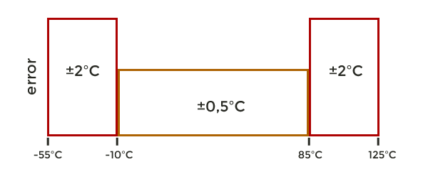
- Measures temperatures from -55°C to +125°C ±0.5°C accuracy from -10°C to +85°C, ±2°C accuracy below or above the aforementioned range. Figure 3
PCB Design
To design the board that will control the temperature sensor I choose an
Attiny 85. The Attiny85 provides an 8 Kb of in-system programable flash, 512 bytes EEPROM, 256 bytes SRAM and 6 I/O lines. The board have a
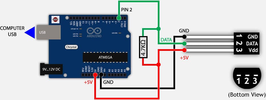
SPI Header and FTDI. To connect the temperature sensor the board has a 6-pin header (only 3 will be used: Vcc, GND and DQ according to the Figure 1).
This sensor and its libraries require a resistance in a range of 4.7 KΩ to 10 kΩ (this value depends of the wire length) between the Vcc and Data wire.
That´s why a 4.99 KΩ resistance is included in the PCB.
The PCB was designed in Eagle following the procedure explained in Week 7 assignment. The schematic and the board can be seen
in Figures 4 and 5.
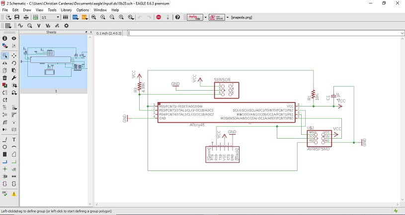
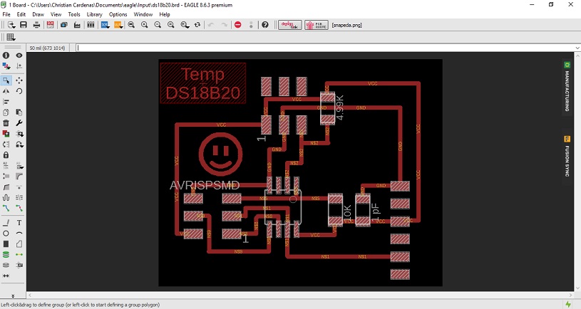
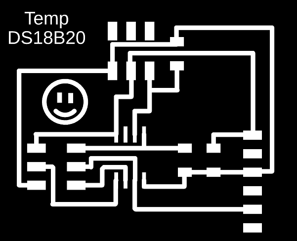
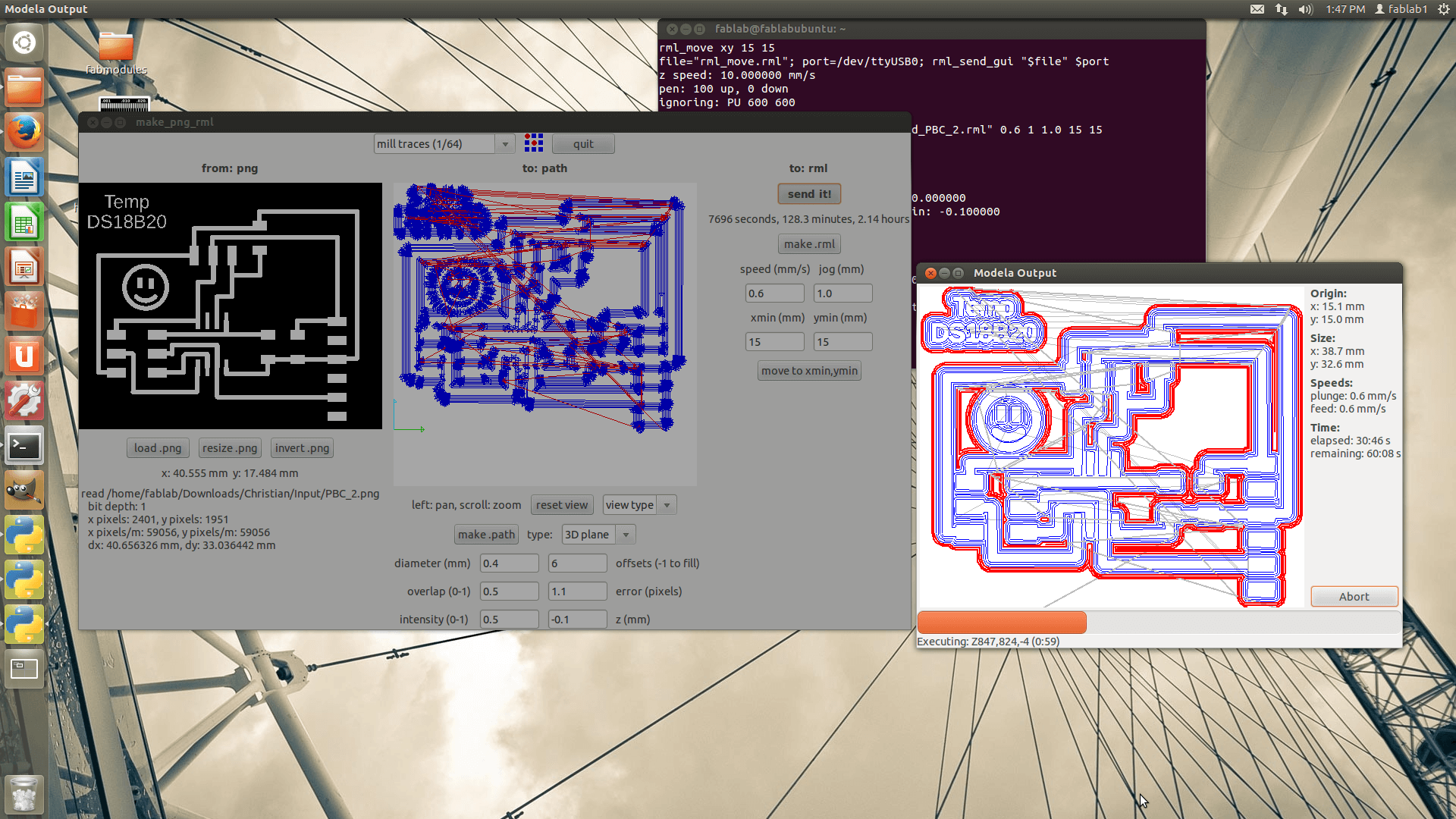
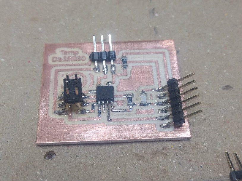
The routes in the board file were done manually using track width of 24 mil and bending style 0 (90 degrees turn), a PNG file is obtained and use to the PCB production. Following the procedure of electronics production of Week 5 and Week 7 the PCB was milled and solder. The final result is showed in the figure 8.
Testing the sensor with Arduino
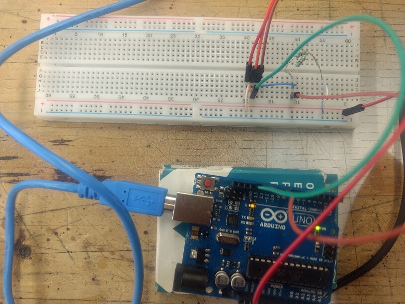
Before to use the sensor with the PCB, is a good idea to test its function with Arduino and a breadboard. As it was mentioned before the DS18B20 sensor has to modes of power supply: parasitic power mode and local power supply. For the Arduino test the local power supply was used (Figure x and x), because is the power supply mode that’s going to work in the PCB.
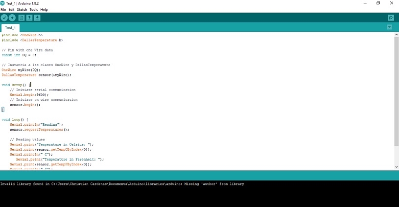
The Arduino code for the sensor is very simple thanks to the use of two libraries: One Wire and Dallas temperature. After Installing the libraries the code is:
After testing the sensor with Arduino and comparing with the IR thermometer (Video) I can say as a conclusion that this sensor offers a very good reading for temperatures.
Controling the sensor with Attiny 85
To program the Attiny85 to control and read the temperature values from sensor there’s two options:
1) Find specific libraries for the MCU and write a program with Atmel or 2) use Arduino as ISP and use the same code from the sensor testing.
The use of libraries is very important for me because I don’t have the experience or the enough knowledge to write them or to program to use the characteristics
of the sensor. I really hope some day to have the knowledge and the expertise to do it. For now, I must use libraries.
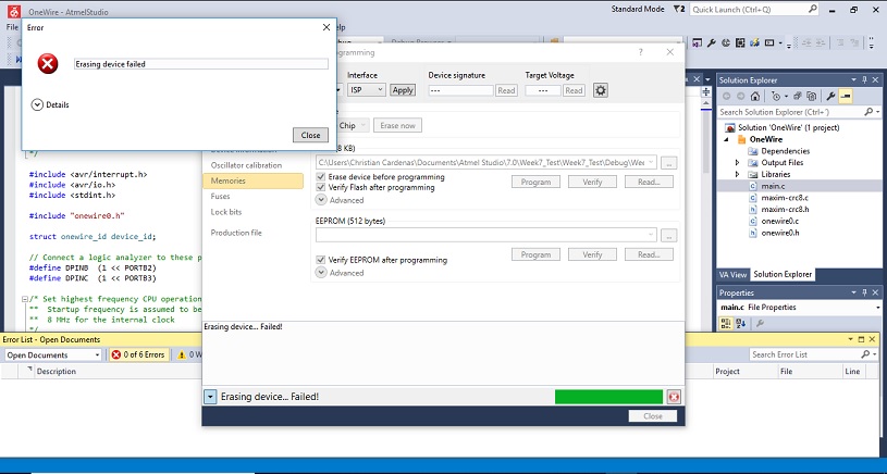
One the libraries that I found was the avr-onewire by nick Andrew. After download the library I tried one of
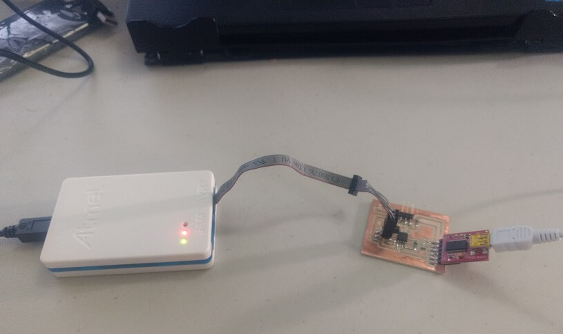
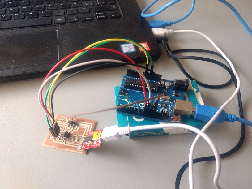
the test program that is include in the library, but after connecting the ATMEL-ICE Programmer and the FTDI cable
(Figure 12, according to the procedure described in Week 9 ) I got an error message (Figure 13). After this error I checked
the connections and everything was fine, so I decided to try programming the board with Arduino.
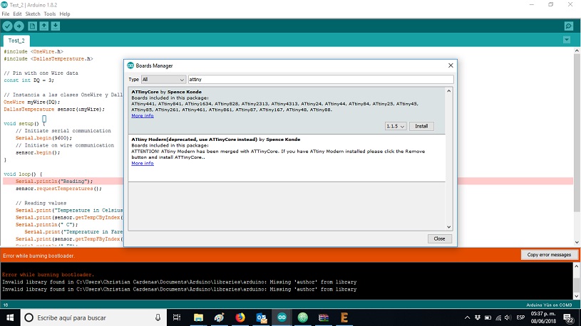
After this error message I tried to use Arduino as ISP, following this tutorial (Figure 14) but some similar error appear. This time the message was: “error while burning bootloader” (Figure 15). After consulting with my local instructor Iván, we conclude that there is a big probability that the Attiny85 is damaged.
After the unsuccessful programing attempts the next step is to replace the Attiny85 and try again. Unfortunately, until now I haven’t had enough time to do it. As soon as I can I´ll do it.
Files
In this section the files generated during the development of the assignment will be available
to download.

|
|
|

|
| Week7.sch | Week7.brd | Week7.png | Test_1.ino |