Assignment
- Make an in-circuit programmer by milling the PCB
- Program the in-circuit programmer made
Personal objectives
- Use the fab modules tool (installation and connection with the Roland
- Develop the ability to complete a circuit board and recognize the different components involve in a circuit (microcontroller, resistors, capacitors, jumpers, etc.)
- Prove the function of the circuit board with a program
Installation of Fab Modules
I decided to install fab modules in my computer as an exercise to test the connection and learn the correct procedure to install and use of the modules, so in the future Fab Lab Querétaro this would be easy. The procedure to install was download the zip file found in (link), then follow the next steps in the terminal (Ubuntu 16.04):
Download the fab_src.zip from http://kokompe.cba.mit.edu/downloads.html
| ~$ unzip fab_src.zip | (Unzip the file) |
| ~$ sudo apt-get install libfg-dev libbooost-thread-dev libboost-system-dev | (Install the prerequisites*) |
| ~$ sudo apt-get install -y python-wxtools | |
| ~$ make fab | (compiles the source code) |
| ~$ sudo make install | (moves the application files to system directories) |
| Optionally add the line PATH=”/home/chris/Downloads/fab_src/bin”:$PATH into your .bashrc** | |
| *Some of the packages needed for fab modules were already install in my laptop, so I just install the missing ones |
| ** The path between " " it will depend of the folder the make fab was made |
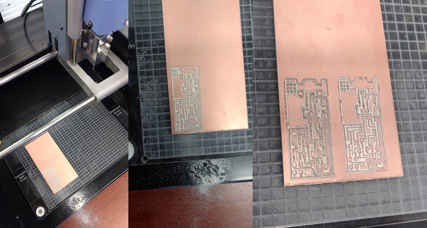
PCB Milling
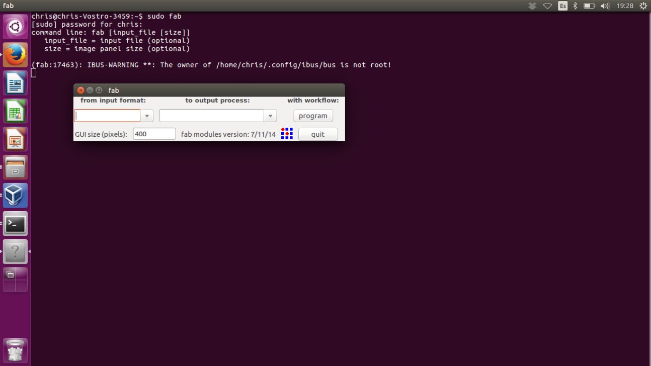
After the installation the modules can be called with the command sudo fab in the terminal (the sudo is necessary because other way the Roland doesn’t accept the controls from the module). Once the firs window of the fab modules is open the next steps should be followed:
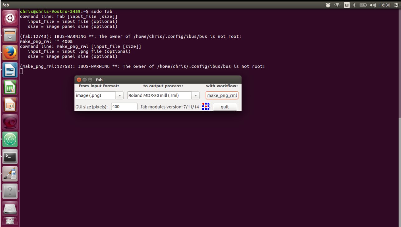
- The input format and the output process should be selected. In this case the selection for input is image (.png) and the output is Roland MDX-20 mill (Figure 2). After the selection below the legend with workflow must appear a make_pgn_rml button.
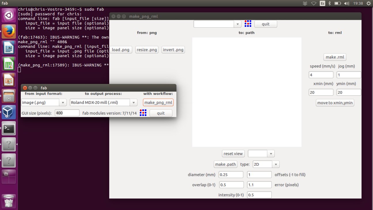
- After click in make_pgn_rml a new window will be open (Figure 3). In this new window the following steps are necessary
- The image with the traces for the circuit board is loaded with load png. In this case the hell.ISP.44.res board (board)
- Then choose the process between: mill traces (1/64); mill traces (0.010); cut out board (1/32); wax rough cut (1/8) and wax finish cut (1/8). In my case I choose the mill traces (1/64).
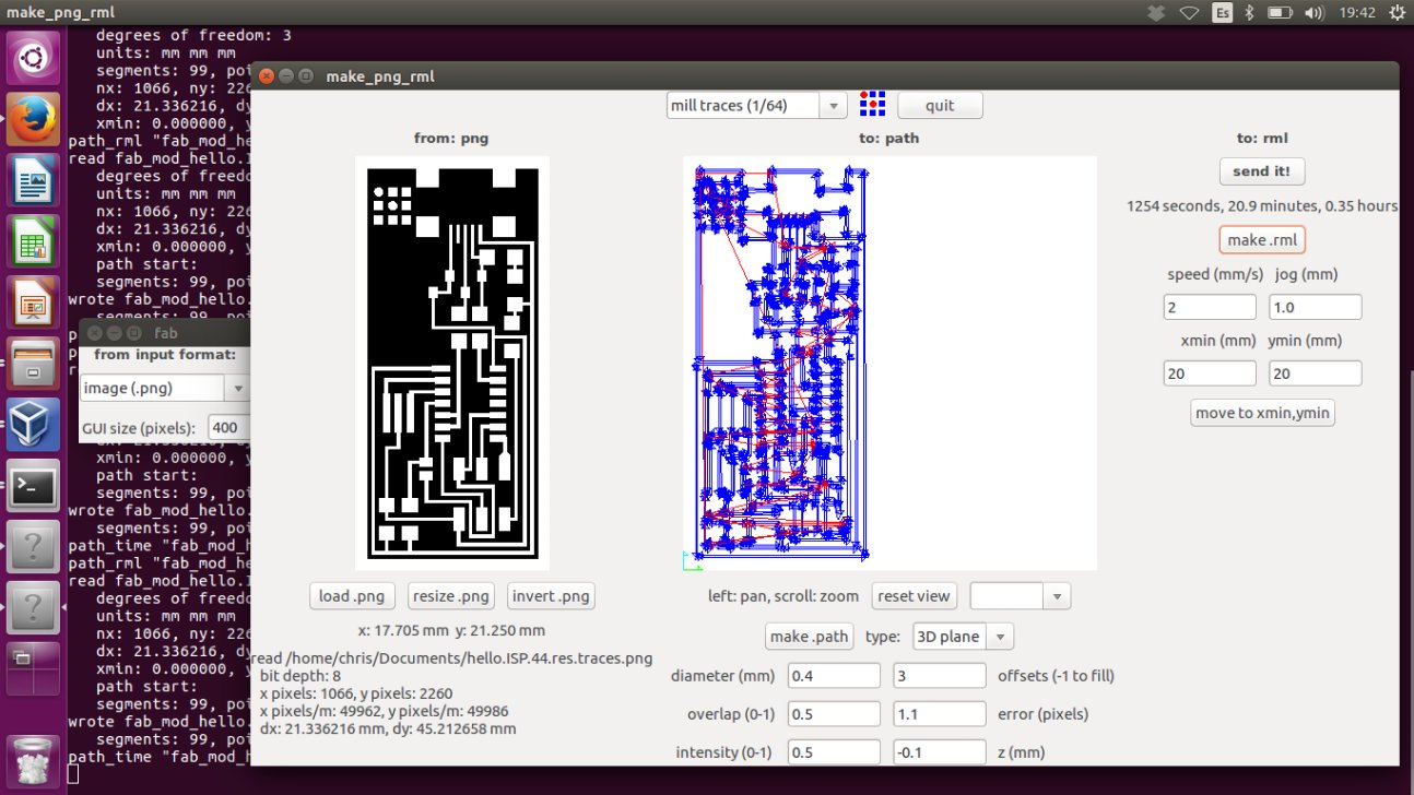
- After configure the parameters wanted for the process and click in make .path a preview with the path of the tool will be show.
(Figure 4) - The last part is to set the speed and the origin of the tool and click the make .rml button. After this the estimated time is shown and the Send it! Button appear. Its important to know that any change in the path or the rml configuration makes necessary to generate a new path and a new rml.
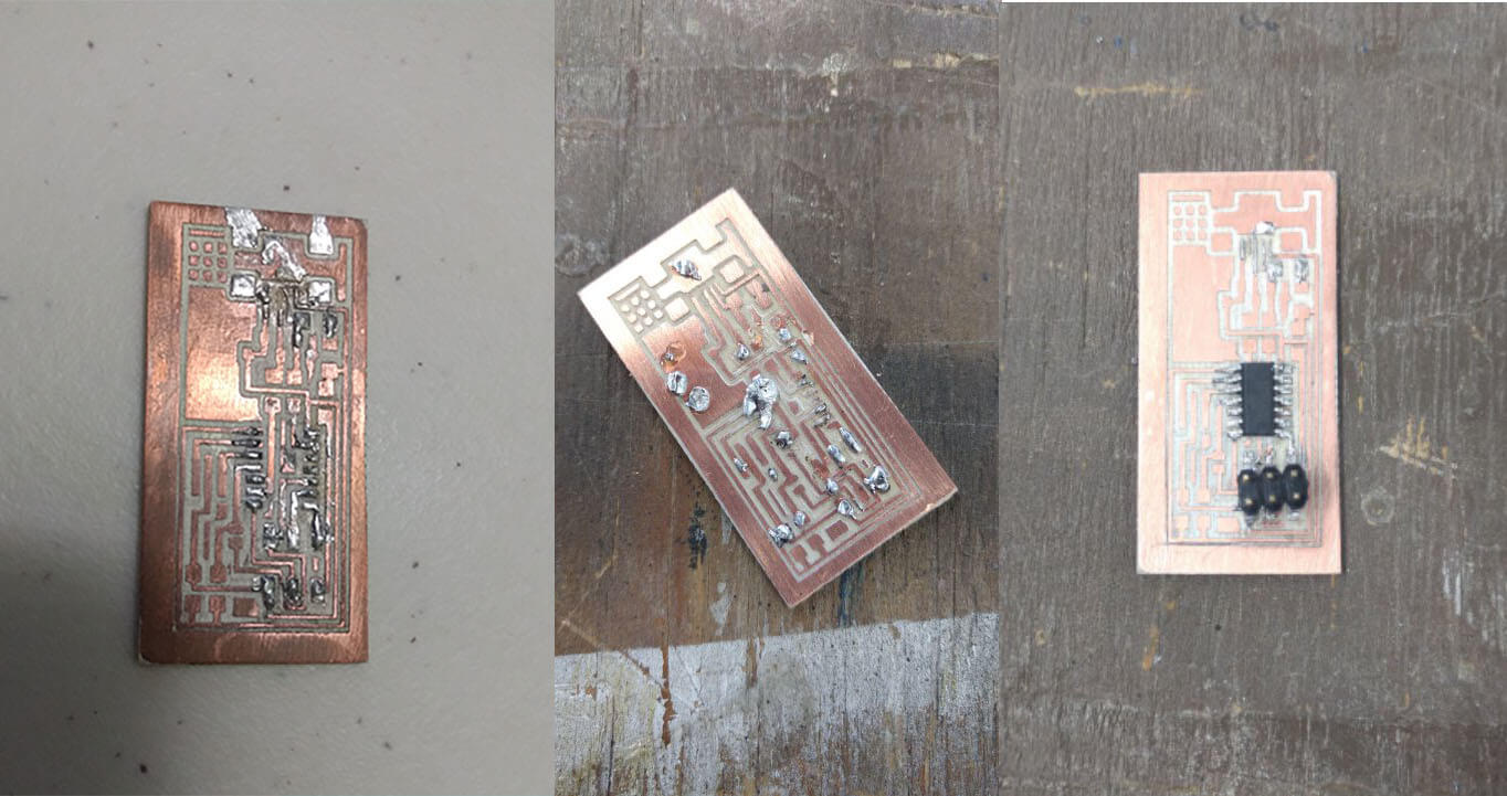
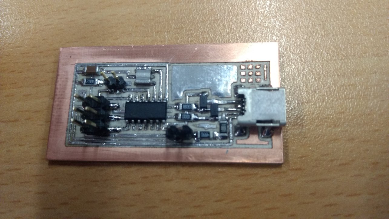
PCB Assembly
Once the PCB is done the assembly of the components in its surface is through solder. As a beginner in this topic this part was quite challenging.
It was necessary several attempts to finally make a decent solder. The biggest problems while the soldering process was the size of the components, and the skill to let the solder
just in the joint between the components and the board.
The technique applied in this case was to first apply solder in all the paths in the board and then place the component and with the soldering iron heat the board and the tip of the
component. In this way the amount of solder is better controlled and the risk to short circuits reduce.
Progamming
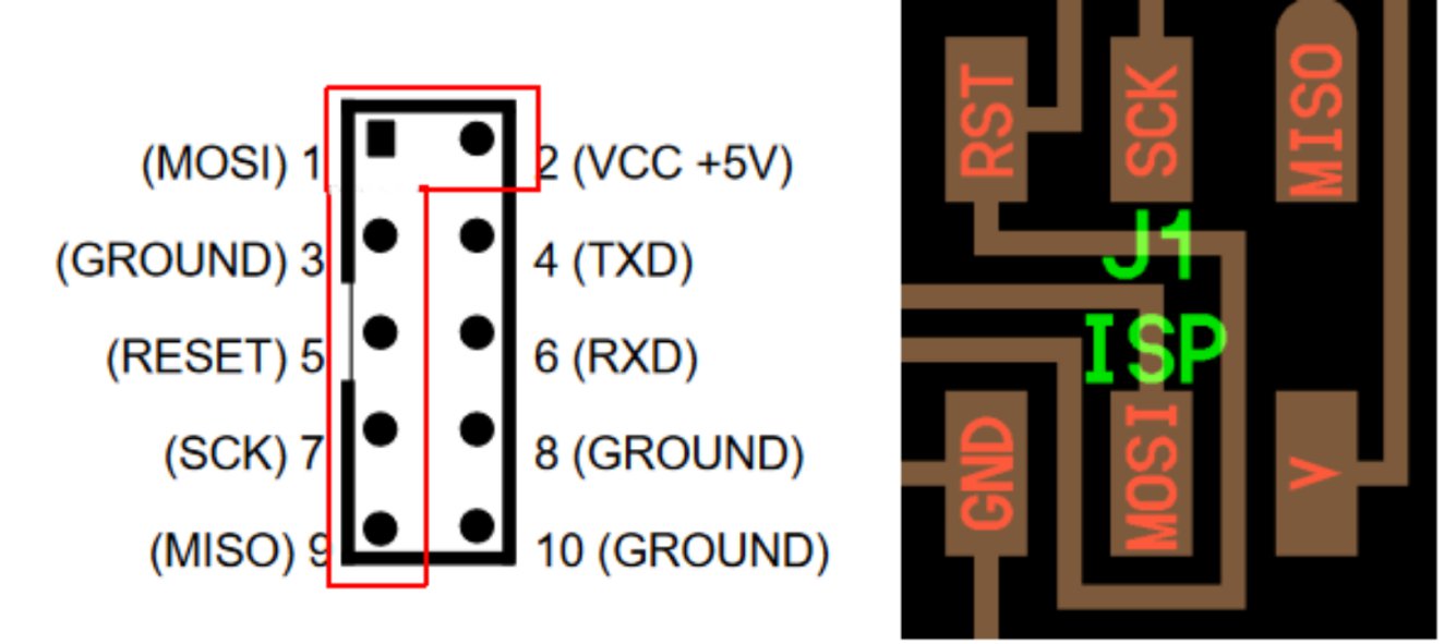
After installing AVRDude in Ubuntu, the firmware was download from the link provided. As the programming of the FabISP was made with an USBASP AVP Programmer (User Guide), and this programmer is an ISP – 10 pin IDC (Figure 8) and the Fab ISP is a 6 pin circuit it was necessary to use a breadboard (Figure 9) and Female to Male Dupont jumpers (this could be easier with Female to female Dupont jumpers but they weren´t available at the time).
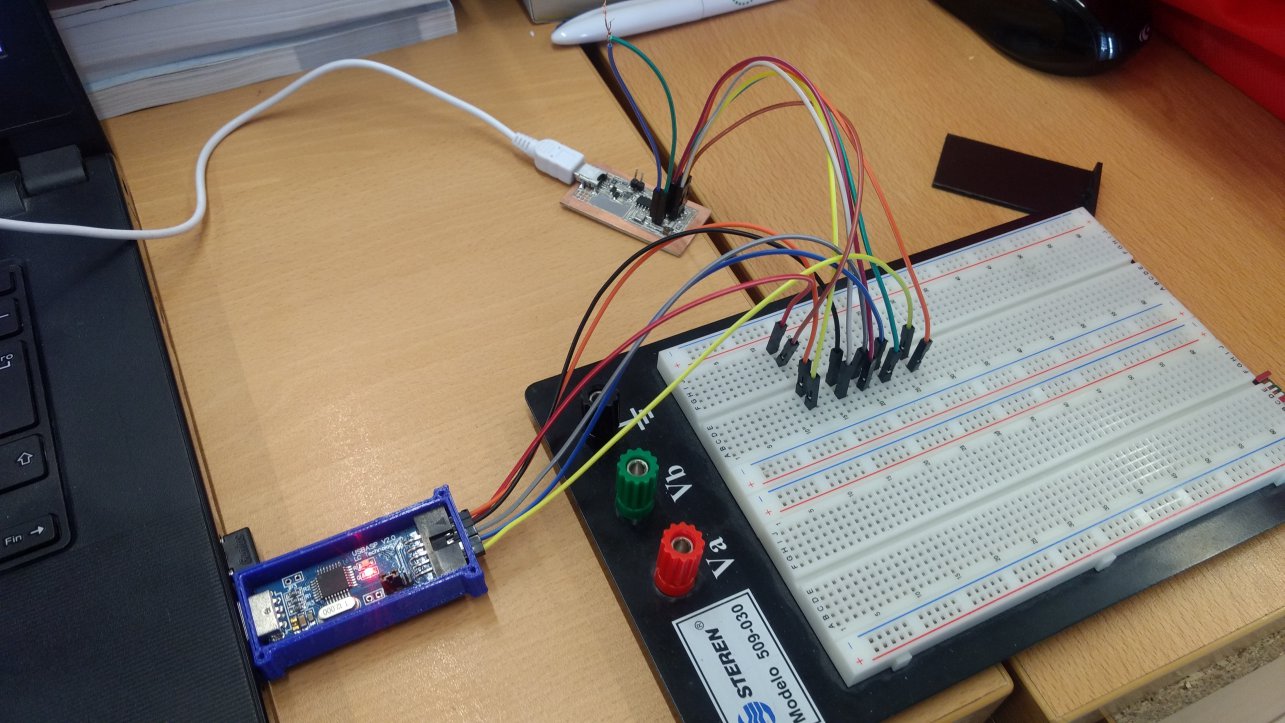
Once the connection was solve it was necessary to add the next line in the Makefile:
| AVRDUDE = avrdude -c usbasp -p USB -p $(DEVICE) |
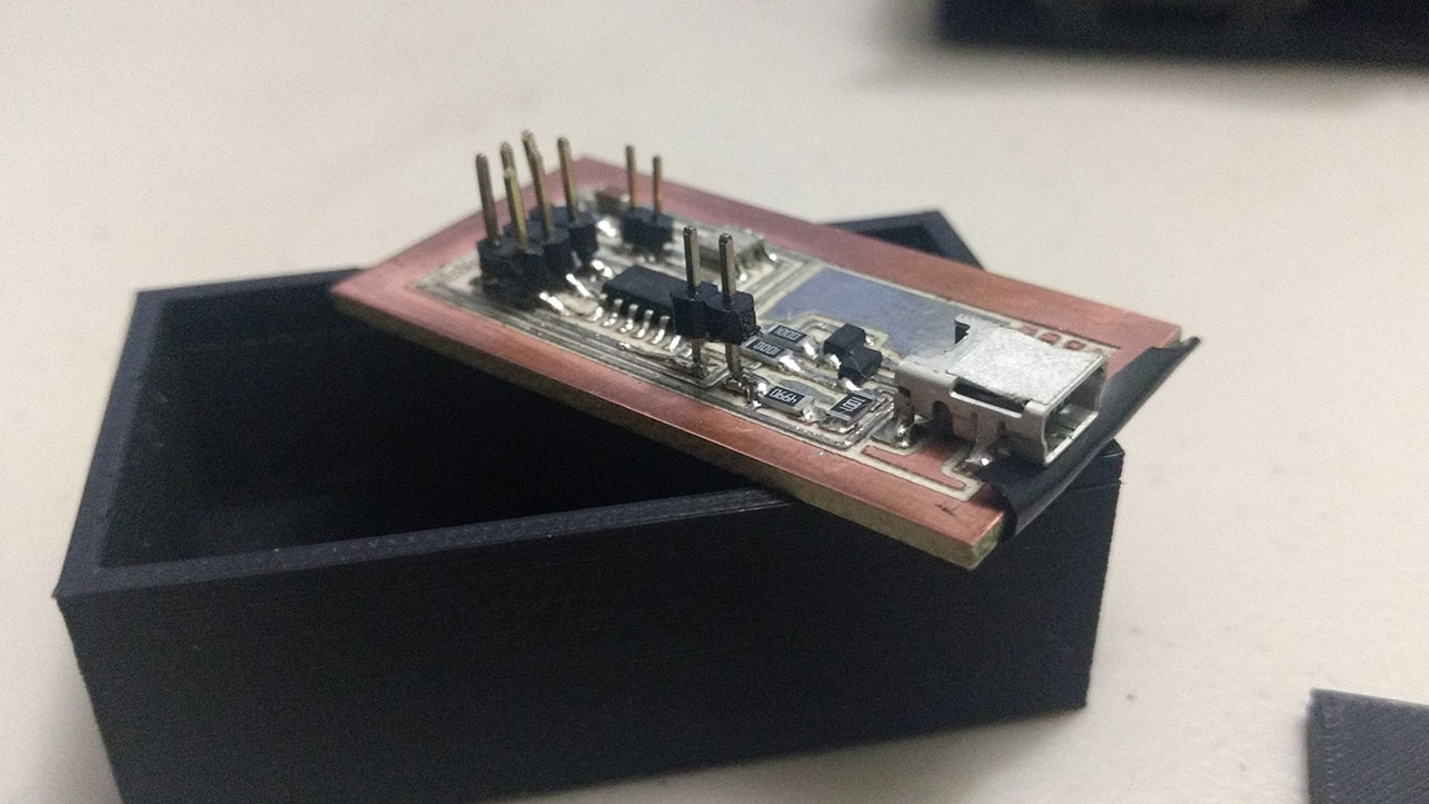
After this the communication was unsuccessful, and the search for problems begin. The first
problem found was a short circuit with the usb port in the FabISP and the edges of the board, this is something that can be improved with the PCB design.
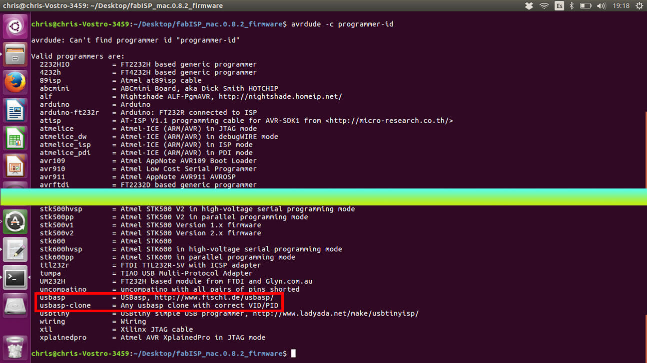
In this case the problem was solved with a small piece of electrical tape (Figure 10). After this the programming wasn’t working yet, so consulting one of
the avrdude options
(~$ avrdude –c programmer-id), in the list of programmer recognized by the utility I found out that there are two types of usbasp programmer
usbasp and usbasp-clone (Figure 11).
Then I changed the device name to “usbasp-clone” and everything went well and the programming didn't have any errors. Even though is necessary to test the FabISP with other board.