Week 14

networking and communication
This week assignment is to make more than two microcontrollers talk together.Here we are going to communicate with boards.
what is baud rate
The baud rate specifies how fast data is sent over a serial line. It’s usually expressed in units of bits-per-second (bps). If you invert the baud rate, you can find out just how long it takes to transmit a single bit. This value determines how long the transmitter holds a serial line high/low or at what period the receiving device samples its line. Baud rates can be just about any value within reason. The only requirement is that both devices operate at the same rate. One of the more common baud rates, especially for simple stuff where speed isn’t critical, is 9600 bps. Other “standard” baud are 1200, 2400, 4800, 19200, 38400, 57600, and 115200.
wiring and hardware
A serial bus consists of just two wires - one for sending data and another for receiving. As such, serial devices should have two serial pins: the receiver, RX, and the transmitter, TX.
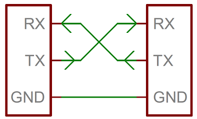
It’s important to note that those RX and TX labels are with respect to the device itself. So the RX from one device should go to the TX of the other, and vice-versa. It’s weird if you’re used to hooking up VCC to VCC, GND to GND, MOSI to MOSI, etc., but it makes sense if you think about it. The transmitter should be talking to the receiver, not to another transmitter.The same technique that we used to get data from our board to computer and read data from bluetooth module
uarts
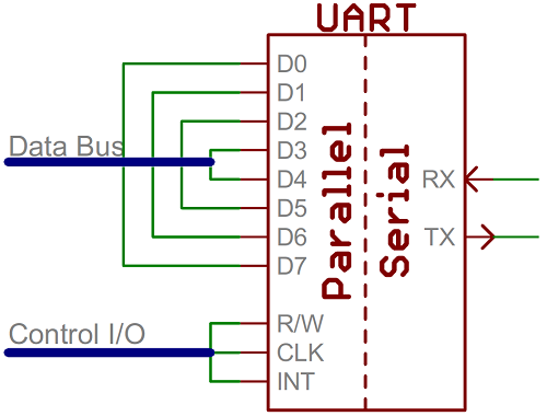
A universal asynchronous receiver/transmitter (UART) is a block of circuitry responsible for implementing serial communication. Essentially, the UART acts as an intermediary between parallel and serial interfaces. On one end of the UART is a bus of eight-or-so data lines (plus some control pins), on the other is the two serial wires - RX and TX.
UARTs do exist as stand-alone ICs, but they’re more commonly found inside microcontrollers. You’ll have to check your microcontroller’s datasheet to see if it has any UARTs. Some have none, some have one, some have many. For example, the Arduino Uno - based on the “old faithful” ATmega328 - has just a single UART, while the Arduino Mega - built on an ATmega2560 - has a whopping four UARTs.
software uarts
If a microcontroller doesn’t have a UART (or doesn’t have enough), the serial interface can be bit-banged - directly controlled by the processor. This is the approach Arduino libraries like SoftwareSerial take , in our ATtiny44 and ATtiny45 doesn't have Hardware UART so I used Software UART by utilizing Arduino SoftwareSerial library.
i2c
So I start with I2C (a.k.a Two wire interface).as i mentined in the introduction section i done some arduino hobby project . one is I2C interfaced Real Time Clock module,I2C interface 16x2 LCD module .. etc. so why I2C , like it's name it's only need two wire for commuication SDA :- Serial Data and SCL :- Serial Clock. The I2C communication bus is very popular and broadly used by many electronic devices because it can be easily implemented in many electronic designs which require communication between a master and multiple slave devices or even multiple master devices.The easy implementations comes with the fact that only two wires are required for communication between up to almost 128 (112) devices when using 7 bits addressing and up to almost 1024 (1008) devices when using 10 bits addressing.
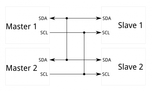
I2C requires a mere two wires, like asynchronous serial, but those two wires can support up to 1008 slave devices. Also, unlike SPI, I2C can support a multi-master system, allowing more than one master to communicate with all devices on the bus (although the master devices can’t talk to each other over the bus and must take turns using the bus lines).
a brief history of i2c
I2C was originally developed in 1982 by Philips for various Philips chips. The original spec allowed for only 100kHz communications, and provided only for 7-bit addresses, limiting the number of devices on the bus to 112 (there are several reserved addresses, which will never be used for valid I2C addresses). In 1992, the first public specification was published, adding a 400kHz fast-mode as well as an expanded 10-bit address space. Much of the time (for instance, in the ATMega328 device on many Arduino-compatible boards) , device support for I2C ends at this point. There are three additional modes specified: fast-mode plus, at 1MHz; high-speed mode, at 3.4MHz; and ultra-fast mode, at 5MHz.(source :- sparkfun)
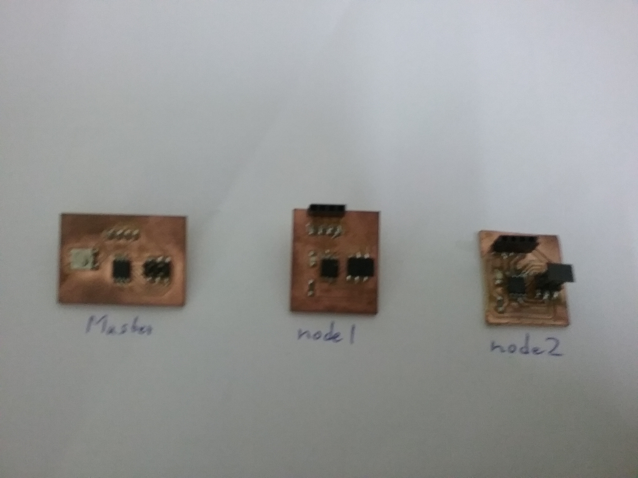
The Things which I Did
First I thought what to make and I got an idea of making a 3 stackable boardsOne board has one button and the other two has one LED each.I programmed it as.
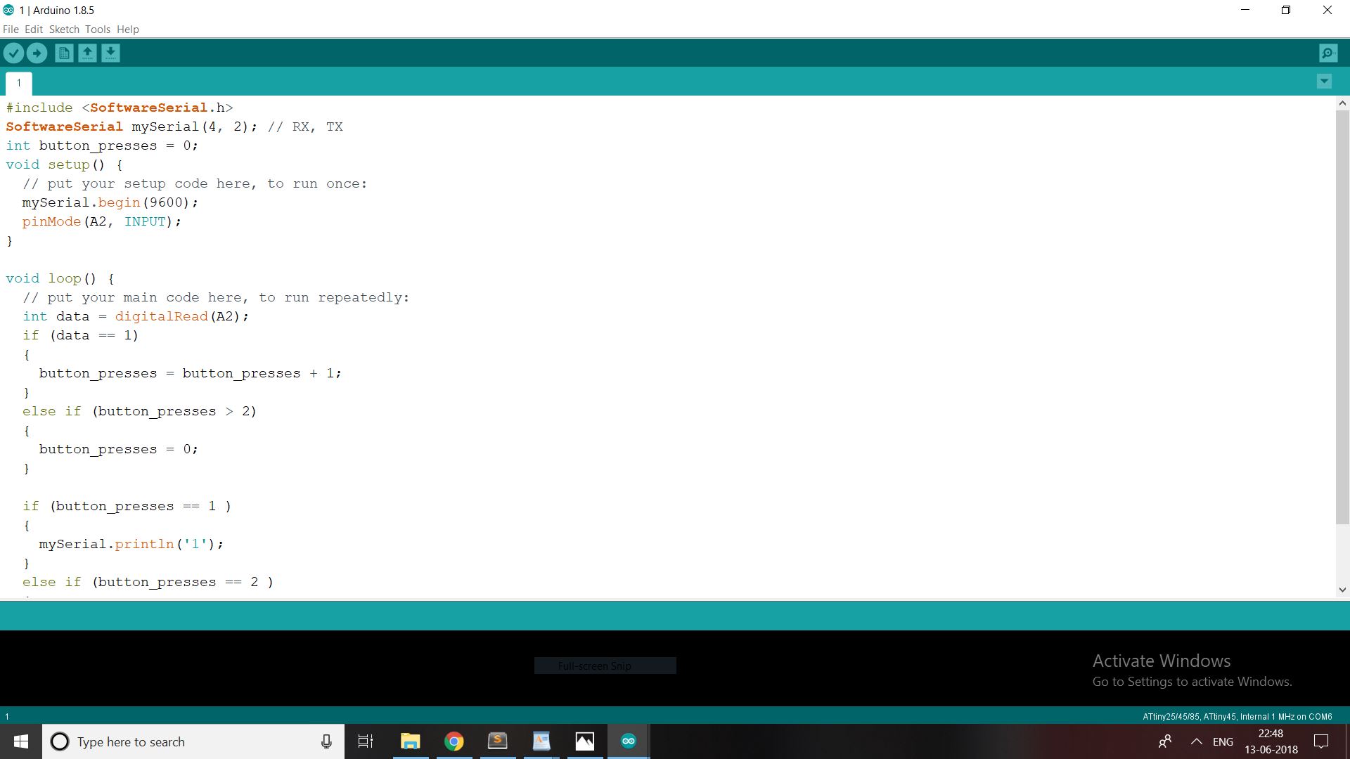
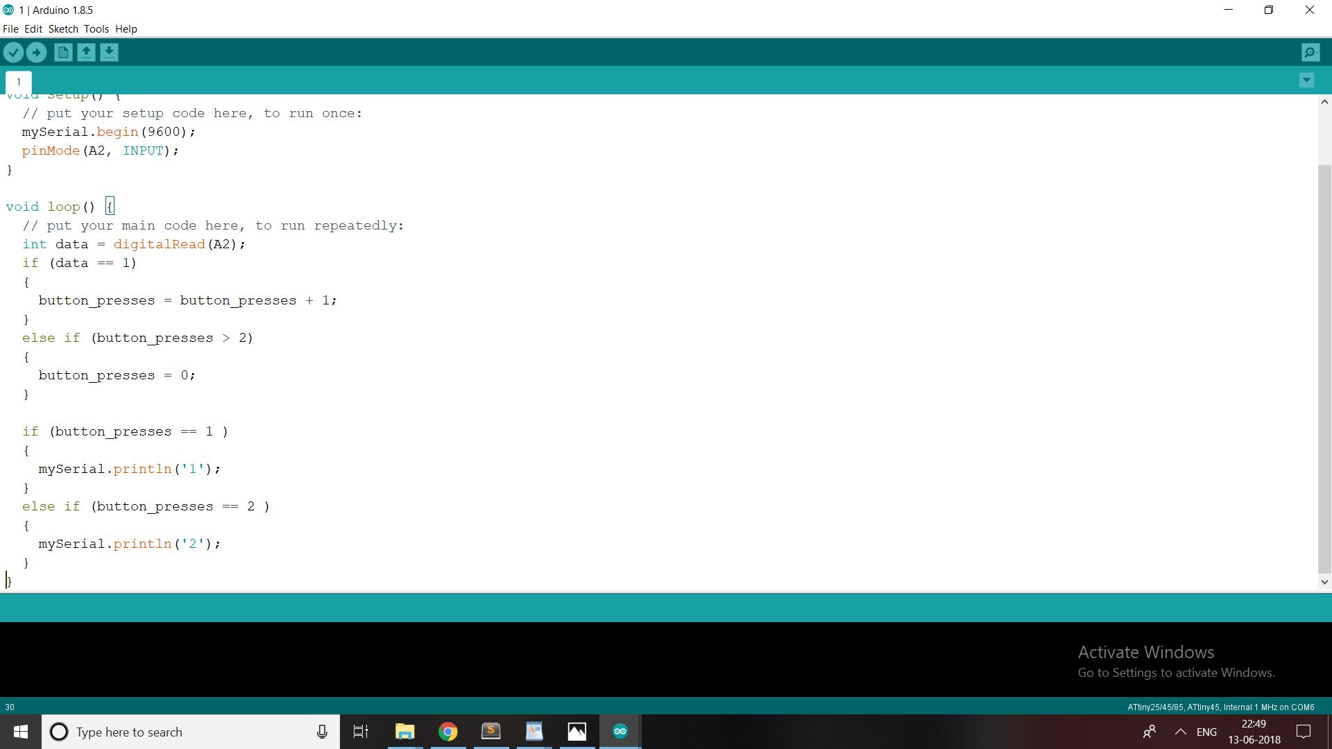
the programme
master
node 1

node 2

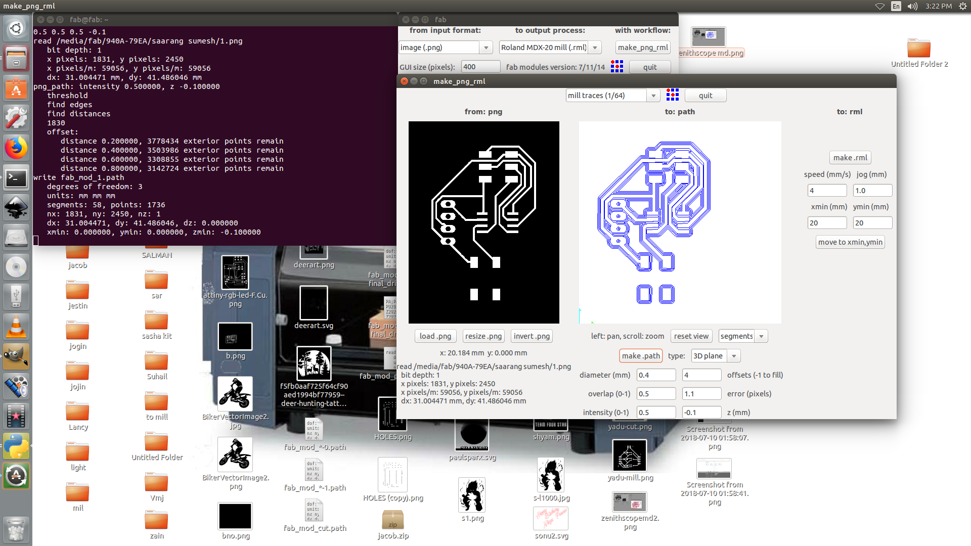
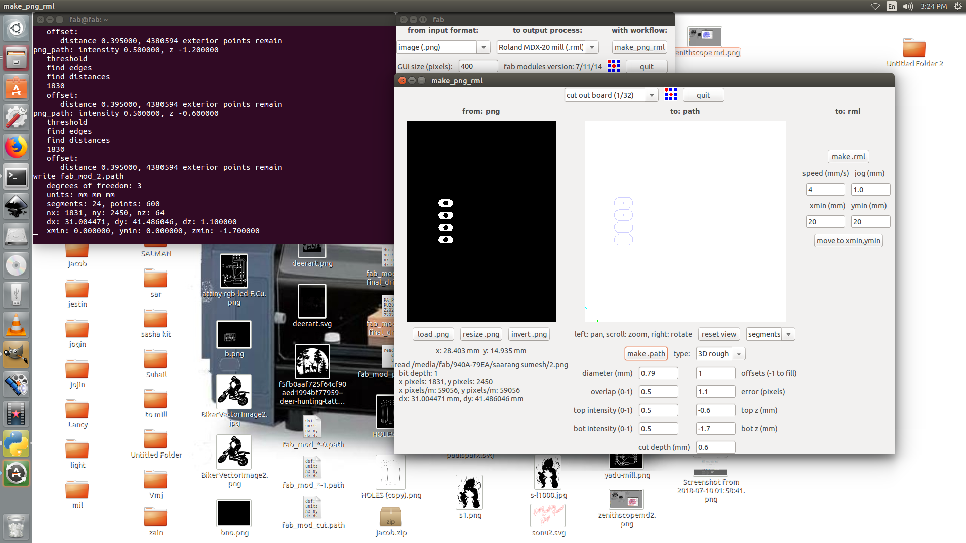
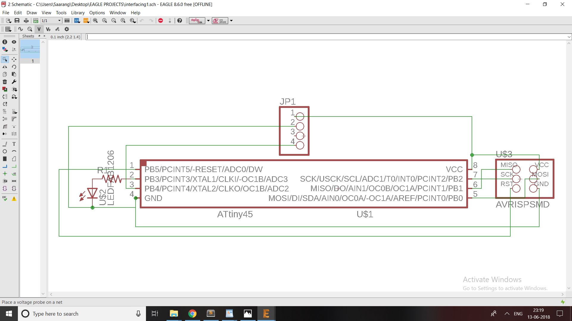
First I designed my board using EAGLE.Then I mill my 3 boards and soldered it fastly.
The board design
master

components used in master
1.Attiny45.
2.push button.
3.2x3 ISP PinHeader.
4.4 female Pin Header.
node 1 and 2
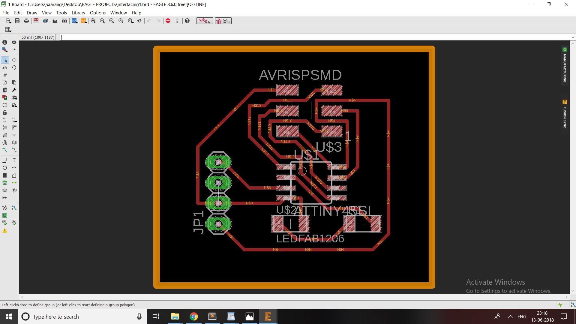
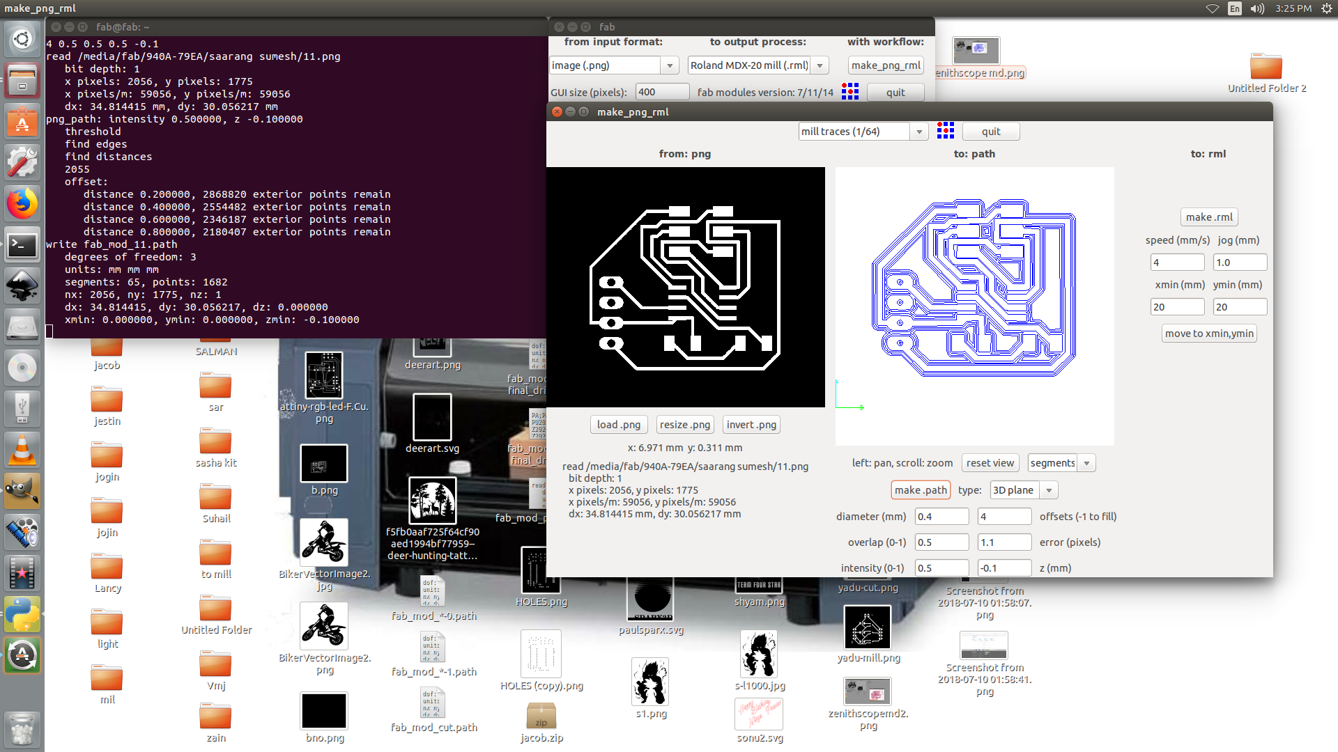
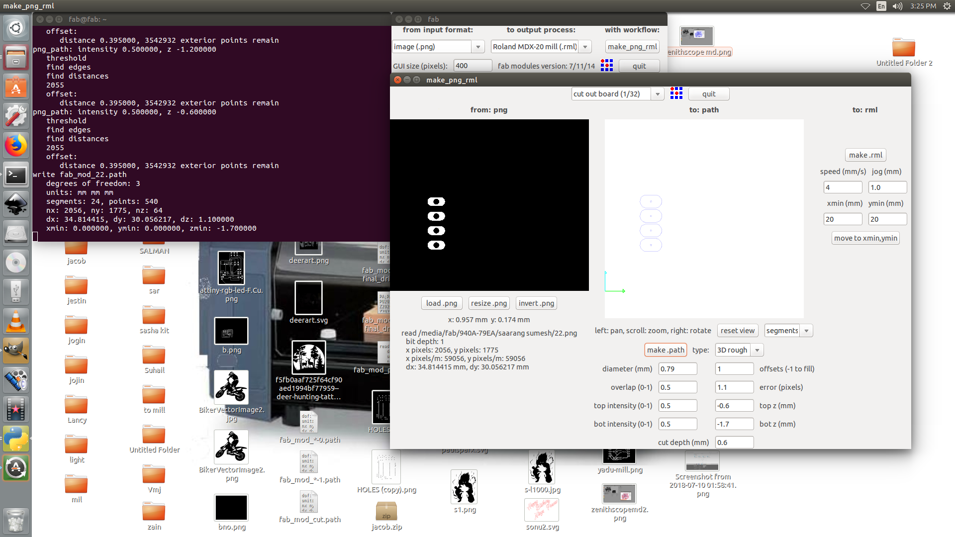
the fab modules of the board
components used for node 1 and node 2
1.Attiny45.
2.LED.
3.Resistor.
4.2x3 ISP PinHeader.
5.female PinHeader