Week 12

output devices
In this week ,Neil gives an introduction about the output devices and give many examples of output devices that we can try.As assignment we have to connect an output device to a board that we designed.Programme it and make it work.So this week i decided to make a board which can run a speaker.
But this time I learned many otherthings like Ripup to make rooted wires unrooted.I also learned how to use the design rules. and I learned auto rooting which is very easy to click a button.
An output device is any piece of computer hardware equipment which converts the electronically generated information into human-readable form[1]. In brief, output unit is responsible for providing the output in user readable form[1]. It can be text, graphics, tactile, audio, and video. Some of the Output devices are Visual Display Units (VDU) i.e. a Monitor, Printer, Graphic Output devices[2], Plotters, Speakers etc. A new type of Output device is been developed these days, known as Speech synthesizer[3], a mechanism attached to the computer which produces verbal output sounding almost like human speeches
Speaker
For this week I used a speaker as an output device.
Regardless of their design, the purpose of speakers is to produce audio output that can be heard by the listener. Speakers are transducers that convert electromagnetic waves into sound waves. The speakers receive audio input from a device such as a computer or an audio receiver
This input may be either in analog or digital form. Analog speakers simply amplify the analog electromagnetic waves into sound waves. Since sound waves are produced in analog form, digital speakers must first convert the digital input to an analog signal, then generate the sound waves. The sound produced by speakers is defined by frequency and amplitude. The frequency determines how high or low the pitch of the sound is.
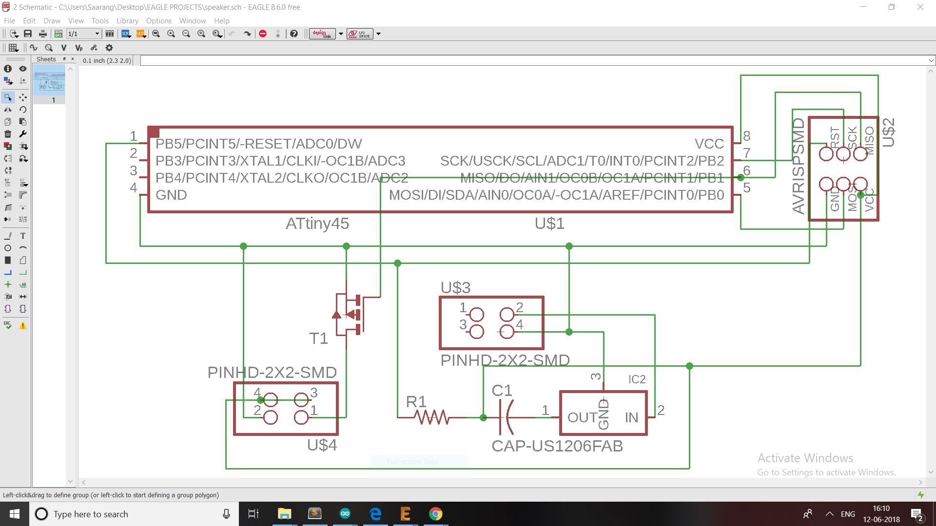
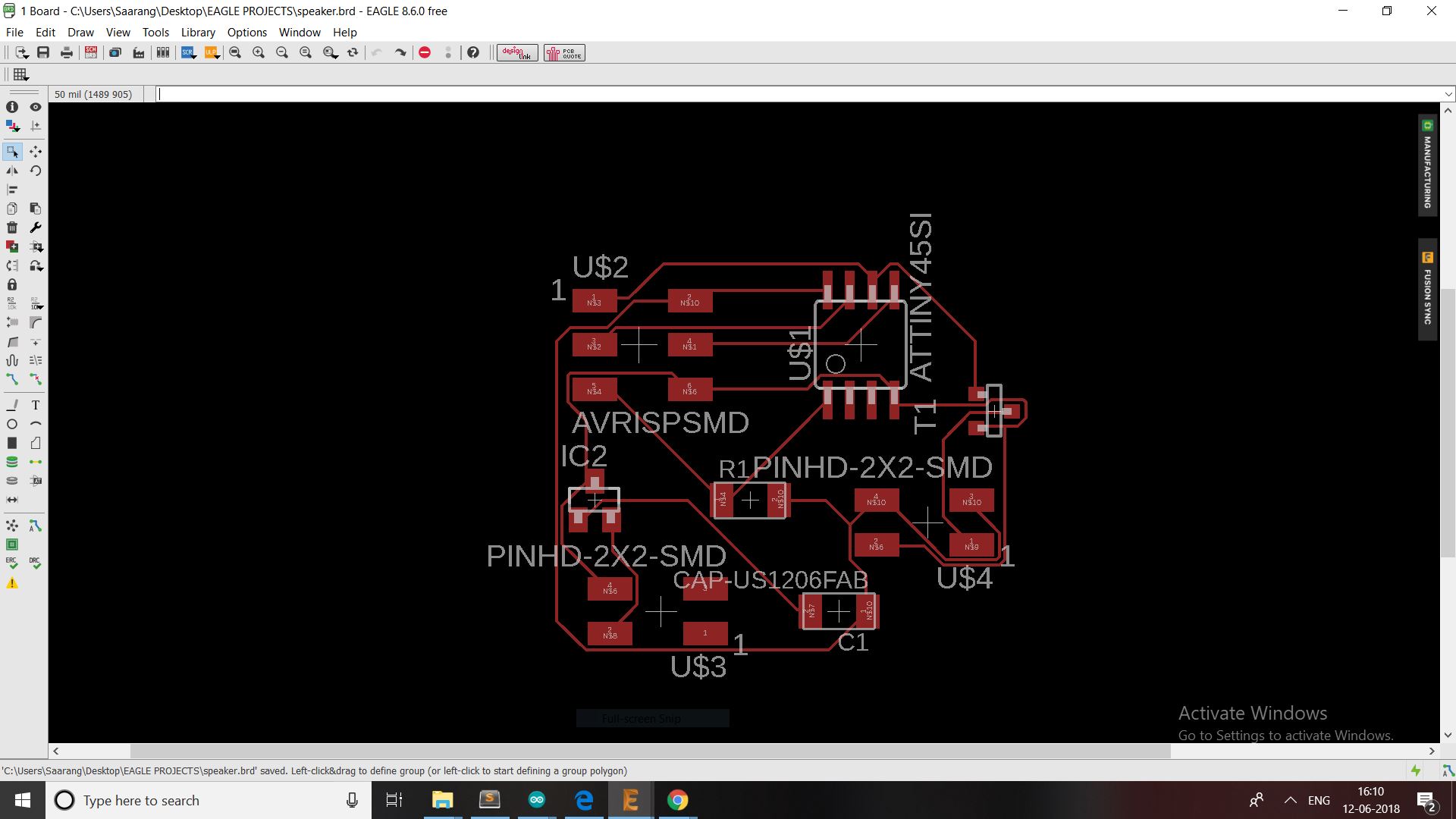
Design of the board
First I have to design the board.For designing I used eagle software
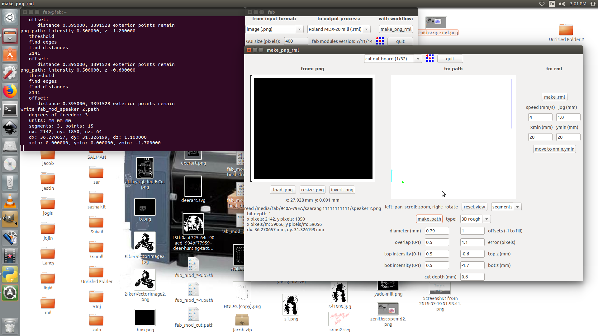
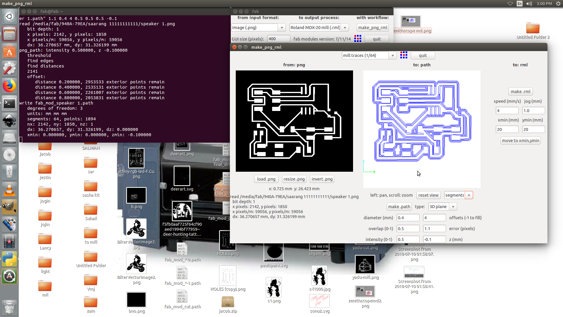
After designing I exported the cut and trace to monochrome.Then I opened it in fab modules and stated to mill .
the fab modules of the board
milling and soldering
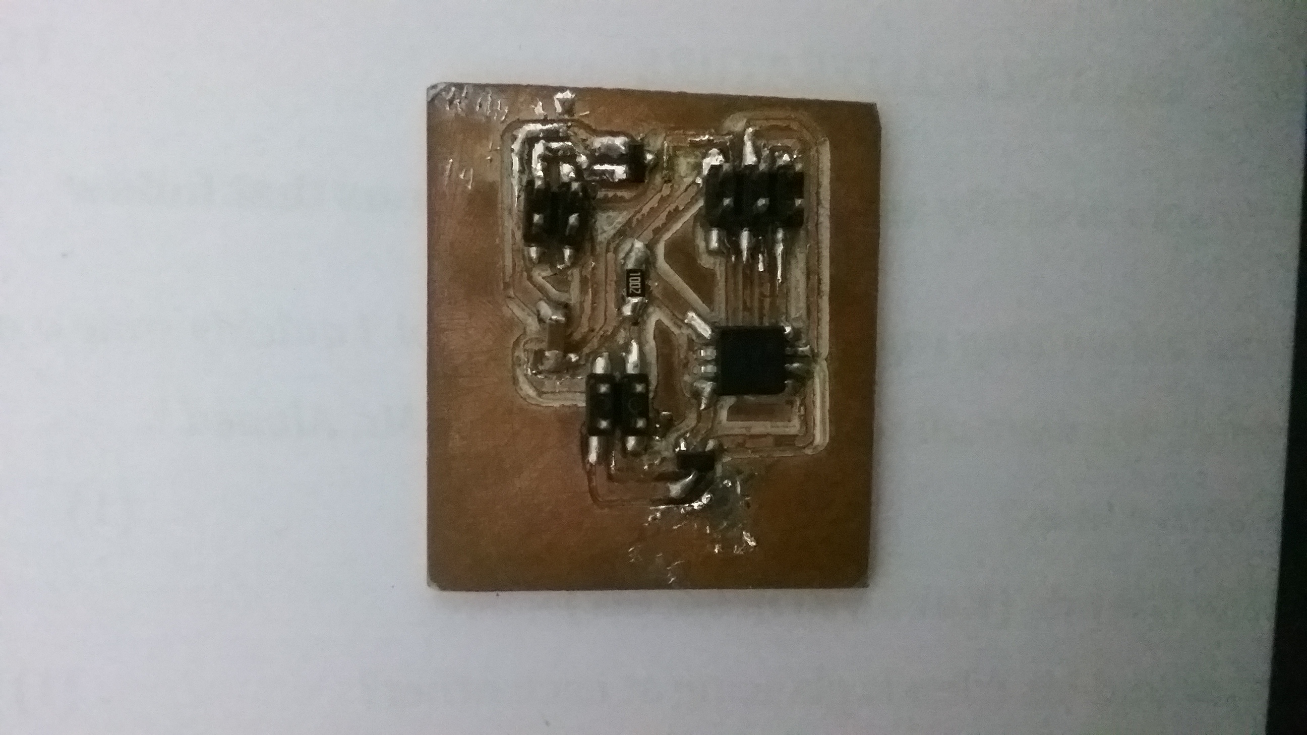
After milling the PCB using modela I soder the board using the components below.
componenets used in the board
1.Attiny 45
2.M Mosfet
3.Voltage regulator
4.Capasitor
5.resistor
6.2x2 PinHeader x2
7.2x3 ISP PinHeader
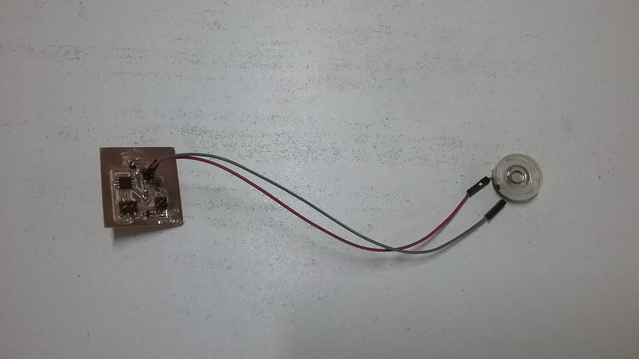
the board after soldering
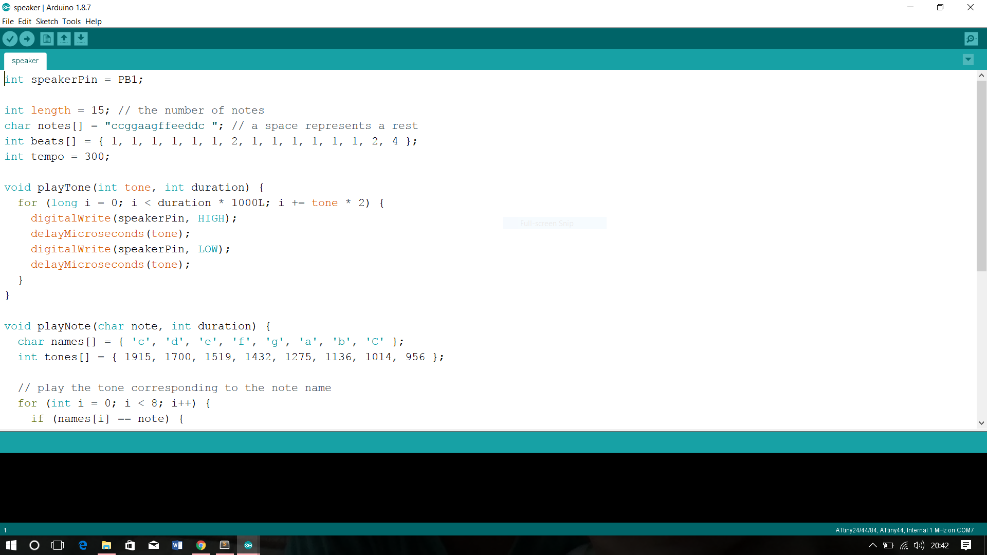
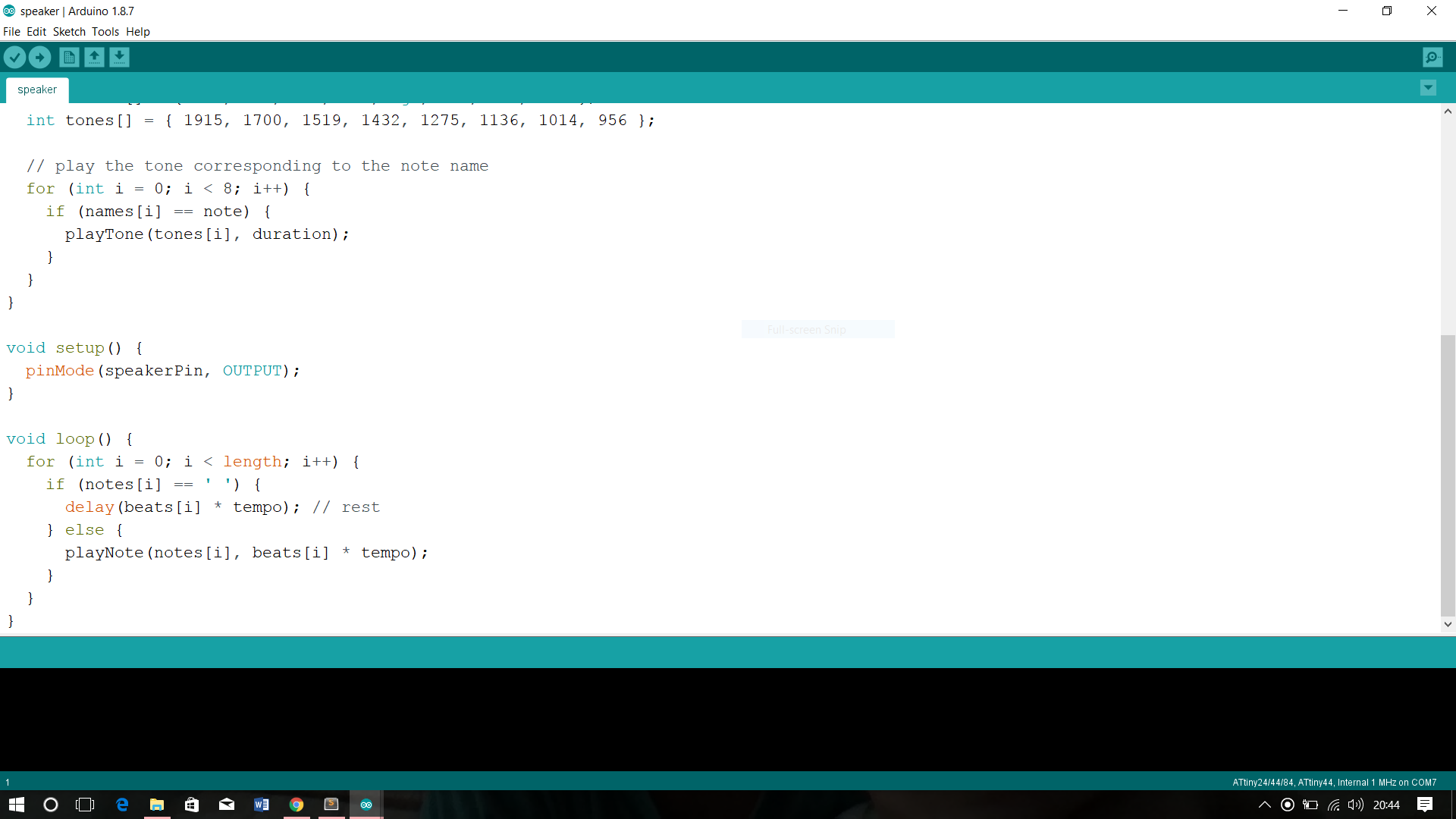
The programme of the board
board with output device