


Computer-Aided Design
Assignment of this week is to play with different 2D and 3D softwares and design sketch of final project using both 2D and 3D softwares.
- 2D software (raster based, vector based)
- 3D software (Parametric, non parametric)
Assigned tasks
create illustration of final project using:
2D Design
Graphic design is the art of arranging images and texts to conveying a message to viewers. in general, they are classified into two sub-sections:
Rasetr based images: Raster graphics/images are composed of pixels, and these type of images often called bitmap images because they are made up of pixels. These raster based images can be identify easily. If we zoom-in enough, we will be able to see the tiny squares which are pixels, especially on the sharp edges of the image.
It is not preferred to use raster images while creating logos and illustrations.
Raster images preferred while working with photographs. When photos are taken by digital camera or photos copied by a scanner, the generated files are raster images.
There are many graphics software which are based on raster, few known of them are:
- MS paint
- Gimp
- Adobe Photoshop
Vector based images: these images never loose their resolution or look blur, doesn't matter how much we scale it or zoom-in it. The edges of vector images always look smooth no matter how large we make it.
We prefer vector images while creating logos or illustrations
Few of vector based softwares are listed here:
- InkScape
- Adobe Illustrator
I will use InkScape and SketchUp Layout for 2D designing.
In this week i used the InkScape software for designing images for web page which represents weekly assignments, few of them are:
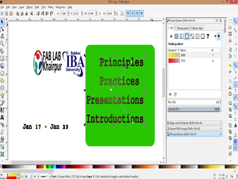


I designed the front panel of my final project on 'SketchUp Layout'. Working with SketchUp is quite handy.
Few snaps are given below of designing process of Final project puter layout in 2D and 3D.

In sketchUp, there is no option for logic gates symbols directly, do I designed all logic gates through using curved lines and pin option. After designing any of gate symbol then I just copy paste it till my required number of logic gates. Given below image shows how I designed each different gate in sketchUp.
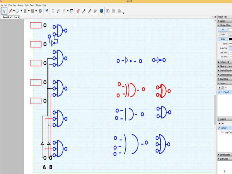


Front panel (2D view) of final project designed in 'SketchUp layout'
3D Design
There are two types of 3D design
Parametric model: is a process in which all the parameters of our 3D design have same relation, for example we designed a house in any parametric based CAD software, then in the last if we want to increase or decrease the size of designed house, we just change the scalled values and all the parameters changed accordingly. Means, there is a relationship between design intent and design response.
Few CAD softwares are listed below which are parametric based:
- SolidWorks
- AutoDesk Fusion 360
I am thinking to use 'SolidWorks' where i need parametric based 3D design.
Non-parametric model: does not contain relationship between dimensions, constraints, edges, and features. If we modify our designed model then it will not allow the update to affect the other designed elements.
Few of the non-parametric based CAD softwares are listed here:
- SketchUp
- Rhinoceros 3D
I designed the 3D model of my final project on 'SketchUp'. And, SketchUp is non-parametric design CAD software. In this week tasks, there is no any such requirement of parametric design. That's why I choose SketchUp, because I already used this software many times.
Here is the first look of 3D design of Final Project.
I designed its box 9/12 inches in dimensions, I set the front height of box as 1.5 inches and for height of back side is 3 inches in order to look attractive.
after designing the 3D box, I export the 2D layout file and just put it upon the 3D box.

3D view of final project designed in 'SketchUp'
Learning outcomes
- Explored different 2D CAD softwares based on 'Raster design' and 'Vector design'.
- Explored different 3D CAD softwares based on 'Parametric' and 'Non-parametric' design.

This work is licensed under a Creative Commons Attribution-NonCommercial 4.0 International License.


