Networking and Communications
Tasks of the week
Individual Assignment.
Group Assignment
This Week's Task
Designing and building a network where two or more devices communicate with each other specifically, that network might be wired or wireless.
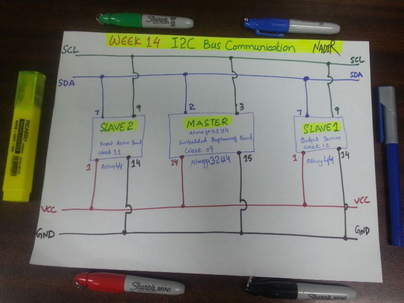
I2C Communication
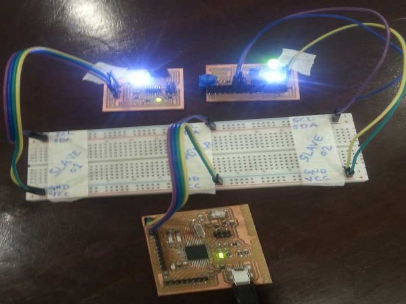
I am following I2C method to communicate different microcontrollers at same time. In I2C method of communication of devices we can communicate devices through serial computer bus. This is pronounced as I2C (I squared C), or I2C (I two C), or IIC (Inter-Integrated Circuit). The I2C bus communication is broadly used in many electronic devices because it can be easily implemented in circuits where communication between devices is required. In this method a master board and different slaves board or multiple master communicate simaltaneousy. This method allows communication between upto 112 slave devices when using 7-bit addressing, and 1008 devices while using 10-bit addressing.
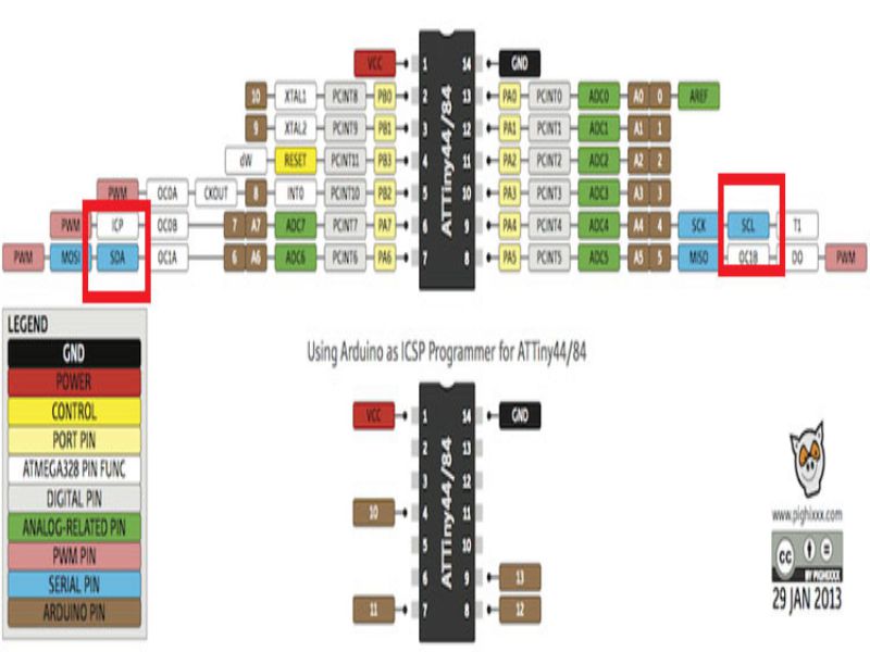
How I2C works?Only two wires are used of each device to be common. These two wire are SDA(Serial Data
Line) and SCL (Serial Clock Line).
Where the SCL line is the clock signal which synchronize the data transfer between the devices on I2C bus, and it is generated by the master device. And, SDL line's
function is to carry the data.
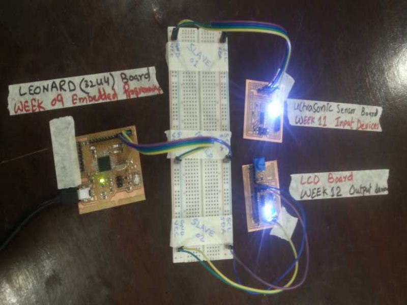
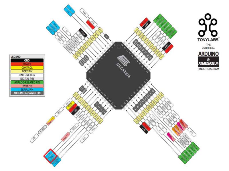
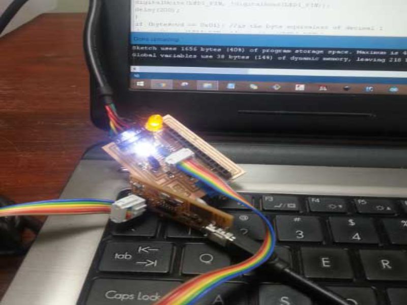
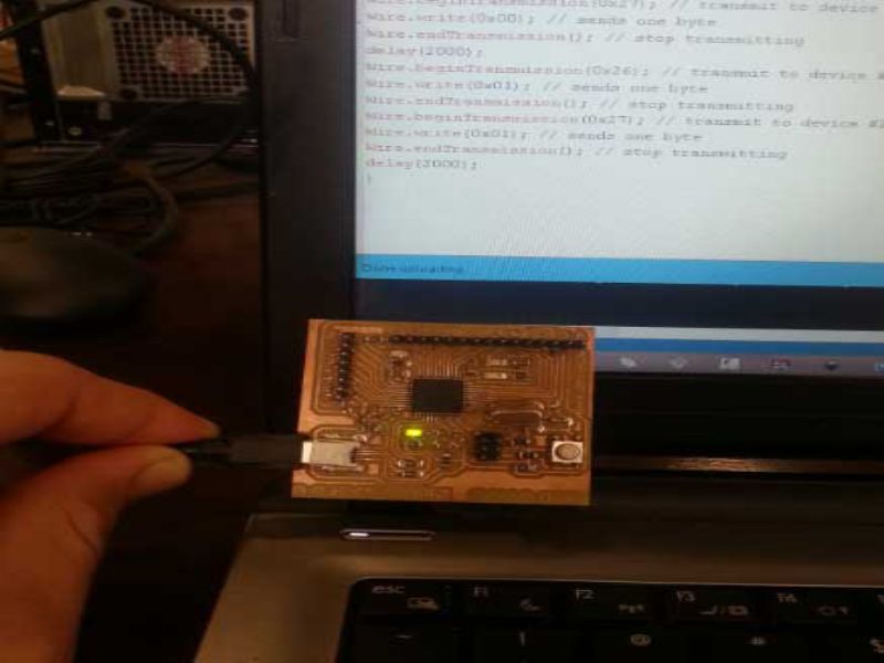
I used one board for Master and two boards for Slaves. For master device, I used my atmega32U4 (Arduino Leonardo) board which I designed in Week 09 Embedded programming. And, for Slaves (slave1 and slave2): For Slave1, I used my board of attiny44 which I designed for Week 11 Input Devices. For Slave2, I used my board of attiny44 which I designed for Week 12 Output Devices.
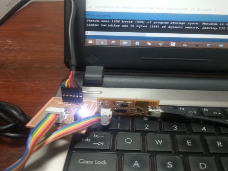
For source code of slaves and master, I explored the fab academy website and found my required source, then I modified the source bit according to my scenario. There are several libraries in arduino which supports this communication. For Master, I downloaded and installed Wire library, and for slaves I downloaded and installed tinywireS library. Without installing these libraries I was unable to upload the code to the devices, so, one must do these pre-requisite things to be on safe side.
Code for Master board: #include "Wire.h"void setup() {
Wire.begin(); // join i2c bus (address optional for master)
}
void loop() {
Wire.beginTransmission(0x26); // transmit to device #26
Wire.write(0x00); // sends one byte
Wire.endTransmission(); // stop transmitting
Wire.beginTransmission(0x27); // transmit to device #27
Wire.write(0x00); // sends one byte
Wire.endTransmission(); // stop transmitting
delay(2000);
Wire.beginTransmission(0x26); // transmit to device #26
Wire.write(0x01); // sends one byte
Wire.endTransmission(); // stop transmitting
Wire.beginTransmission(0x27); // transmit to device #27
Wire.write(0x01); // sends one byte
Wire.endTransmission(); // stop transmitting
delay(2000);
}
Code for Slave boards: //Slave 1 address is 0x26
//Slave 2 address is 0x27
//used board of week 11 for slave 1
//used board of week 12 for slave 2
//attiny44
#include "TinyWireS.h"
#define I2C_SLAVE_ADDR 0x26 //define slave address, 2nd slave has address 0x27
#define LED1_PIN 8 //PB2 (pin5 of tiny44)
void setup(){
pinMode(LED1_PIN, OUTPUT);
Blink(LED1_PIN,3); // show it's alive, blink three times
TinyWireS.begin(I2C_SLAVE_ADDR); //initialize I2C lib and setup slave address
}
void loop (){
byte byteRcvd = 0x00;
if (TinyWireS.available()){ // get I2C input from slave
digitalWrite(LED1_PIN, HIGH);
delay(100);
byteRcvd = TinyWireS.receive(); //get the byte from master, returns next byte in received buffer
if (byteRcvd == 0){
digitalWrite(LED1_PIN, !digitalRead(LED1_PIN));
delay(200);
}
if (byteRcvd == 0x01){ //is the byte equivalent of decimal 1
digitalWrite(LED1_PIN, !digitalRead(LED1_PIN));
delay(200);
}}}
void Blink(byte led, byte times){ // poor man's display
for (byte i=0; i(less than) times; i++){
digitalWrite(led,HIGH);
delay (250);
digitalWrite(led,LOW);
delay (250);
}}

Learning outcomes
- Practically visualized the communication between SLaves and Master through this I2C communication method
- Found this method of communication easy by simply connectiong two main wires SDA and SCL.
- Implementation of I2C is easy in electronic devices when they require communication.

This work is licensed under a Creative Commons Attribution-NonCommercial 4.0 International License.