
Output Devices
Tasks of the week
Group Assignment
Individual Assignment.
Group Task
In this week's group task, we have to measure the power consumption of an output device.
Measuring Power Consumption of RGB LEDs
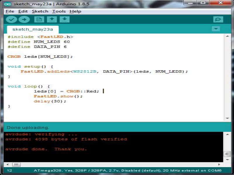
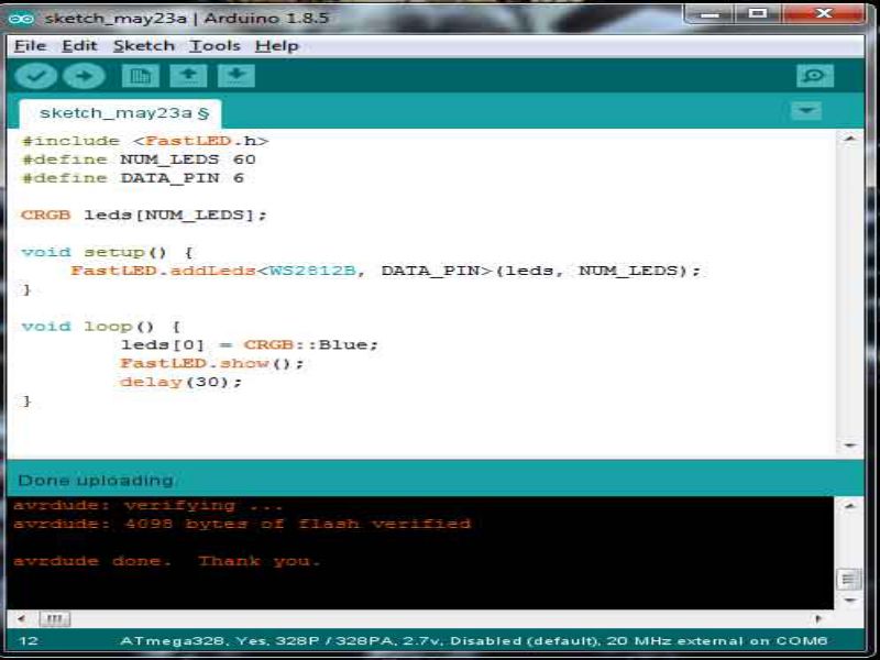
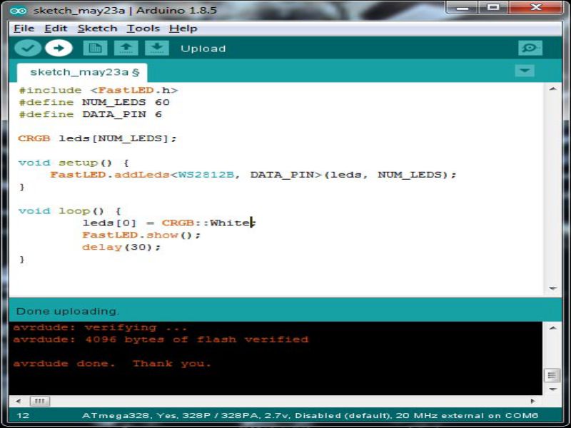
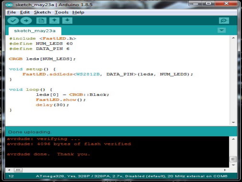
As one of our project is on RGB LEDs so we decide to find the power consumption of RGBs on different color pattern. We write some codes which blink 1 RGB with specific color and measure current on that project.
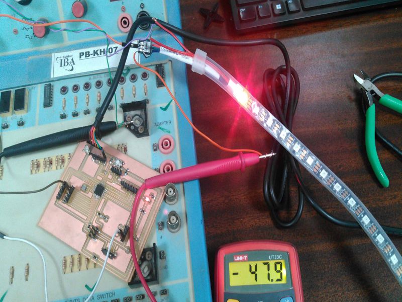
The current is measured 47mA which is multiplied with 5 Volts is equal to 235mW

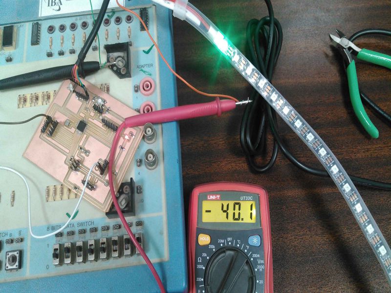
The current is measured 40mA which is multiplied with 5 Volts is equal to 200mW
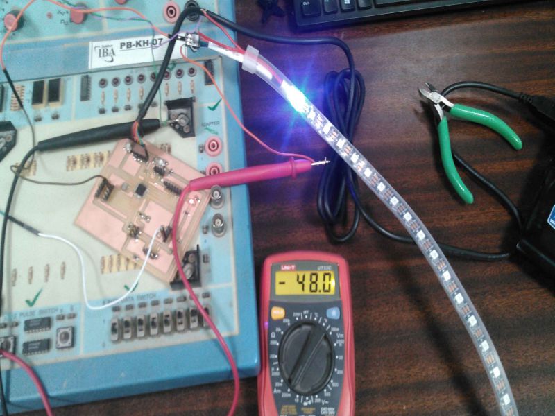
The current is measured 48mA which is multiplied with 5 Volts is equal to 240mW
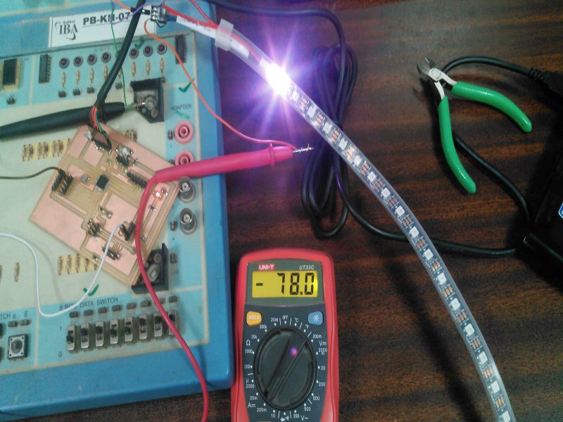
The current is measured 78mA which is multiplied with 5 Volts is equal to 390mW
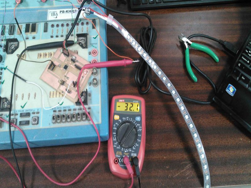
The current is measured 32.1mA which is multiplied with 5 Volts is equal to 160.5mW
Different colors have different current consumptions. As per results we found that green color have low power consumption and white has maximum power consumption.
Individual Task
As Individual task for this week, I choose to embed a 16X02 LCD to Atiny 44 IC. So, for that I designed it on eagle. Before designing it, I read the pin-configuration of LCD, here the LCD which I used is "Standard HD44780 LCD".
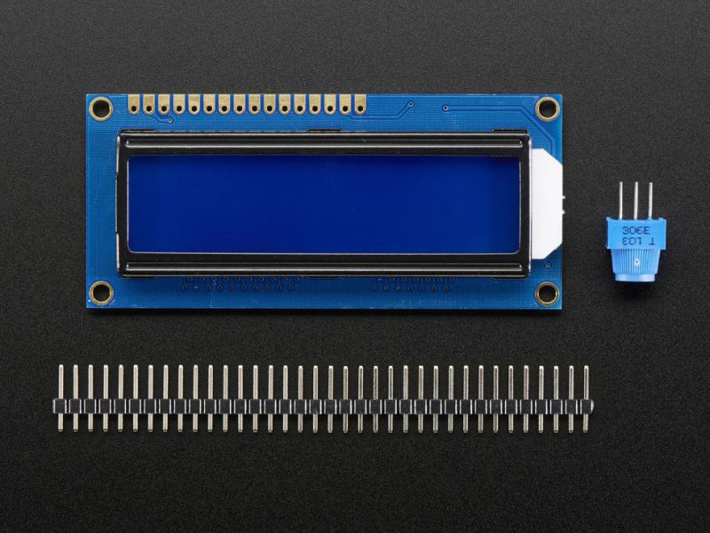
Basic description about the used LCD are given here for better understanding:
- 16 characters wide, 2 rows.
- White text on blue background.
- Increase/Decrease the brightness of the LCD through a potentiometer.
- pin 01 Ground connected to pin no.14 of the attiny44.
- pin 02 VCC connected to pin no.01 of the attiny44.
- pin 03 10K potentiometer for varying brightness of the LCD, connected to 2nd pin of potentiometer, 1st and 3rd terminal of potentiometer connected with VCC and Ground of attiny44.
- pin 04 Register Select (RS) connected to pin no.08 of the attiny44 (this pin of IC also used as MISO).
- pin 05 Read/Write (R/W) connected to ground, pin no.14 of the attiny44.
- pin 06 Enable connected to pin no.09 of the attiny44 (this pin of IC also used as SCK).
- pin 07 Data Pin 0 Not Connected (NC).
- pin 08 Data Pin 1 Not Connected (NC).
- pin 09 Data Pin 2 Not Connected (NC).
- pin 10 Data Pin 3 Not Connected (NC).
- pin 11 Data Pin 4 Connected to pin no.10 (PA3) of attiny44.
- pin 12 Data Pin 5 Connected to pin no.11 (PA2) of attiny44.
- pin 13 Data Pin 6 Connected to pin no.12 (PA1) of attiny44.
- pin 14 Data Pin 7 Connected to pin no.13 (PA0) of attiny44.
- pin 15 VCC connected to pin no.01 of the attiny44.
- pin 16 Ground connected to pin no.14 of the attiny44.
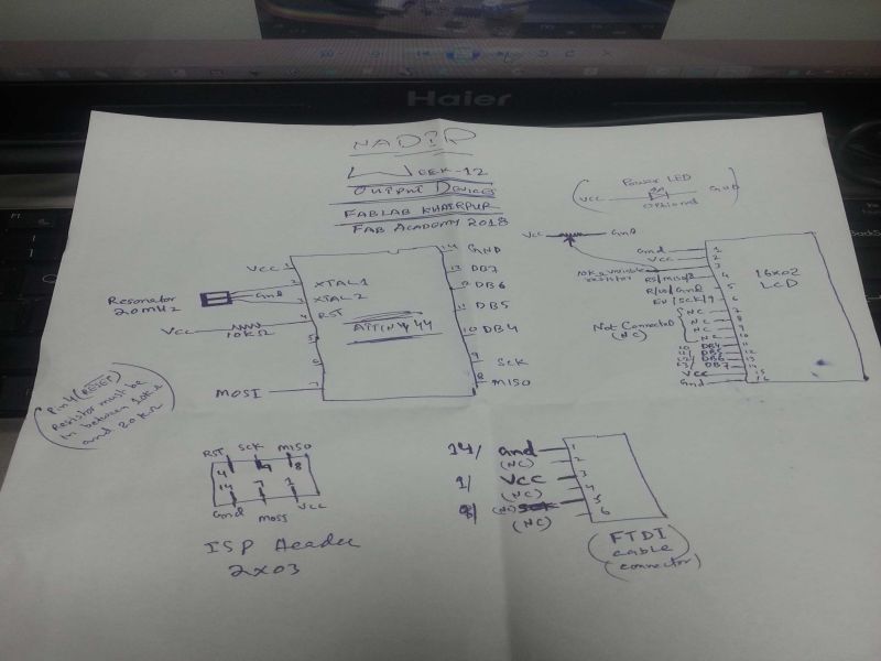
I sketched its design on page, to assemble and connection of the each and every pin of the required circuit for easiness in designing in eagle. the Sketch is shown here:
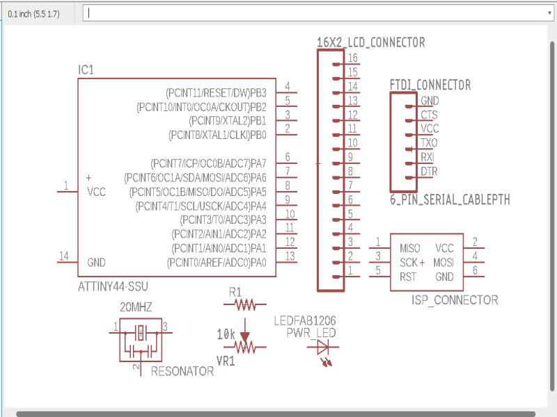
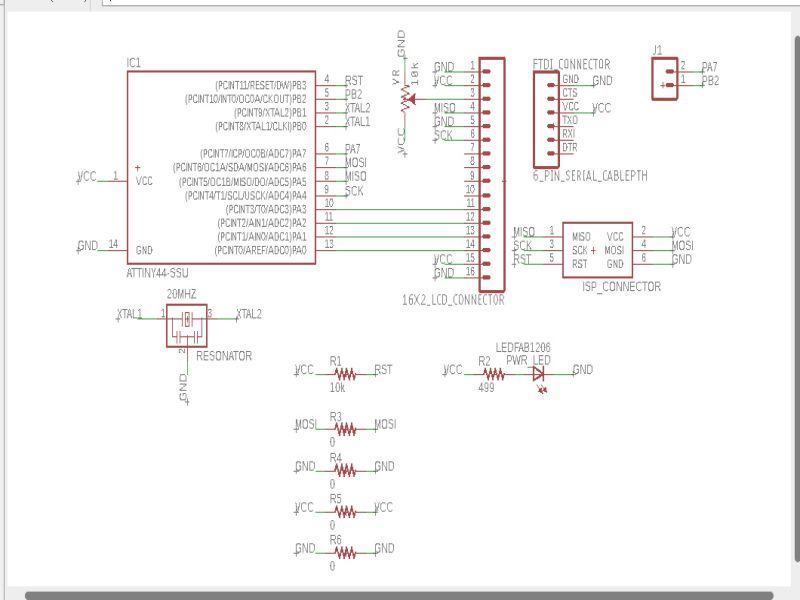
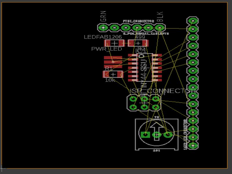
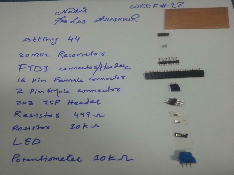
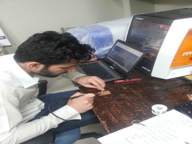
Now it is the time to design and implement above sketch on "Eagle". I collect all required components in "schematic" part of the eagle software then make connections to them. After connecting the required connections of components, I went to "board" part where I gave final shape to my board.
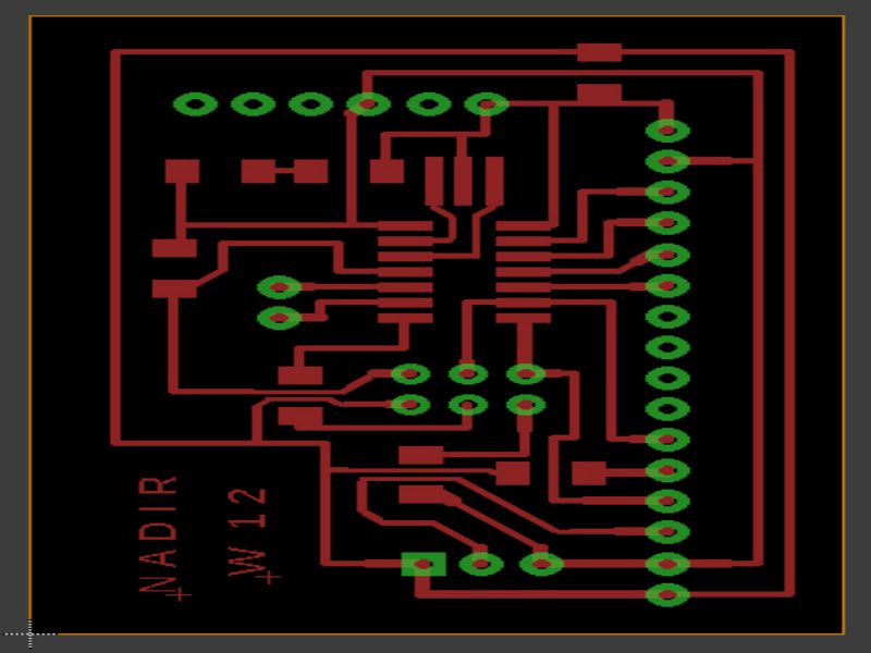
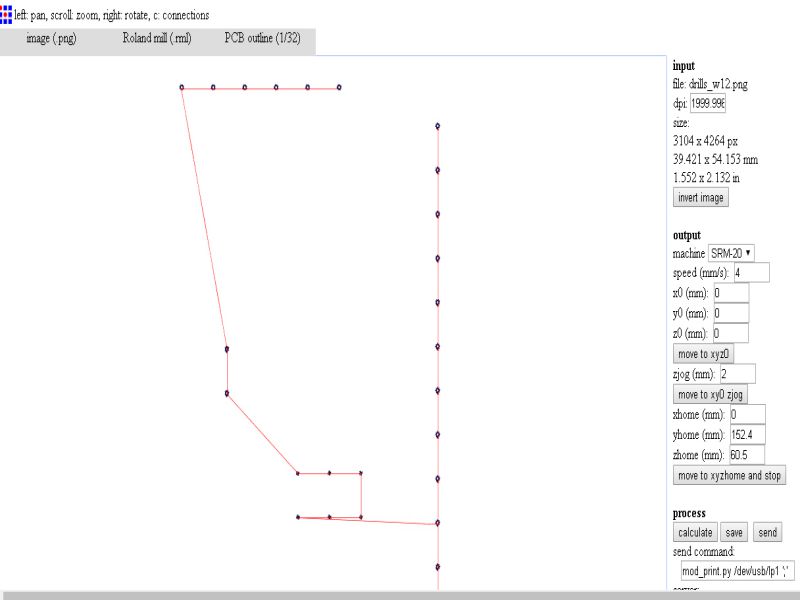
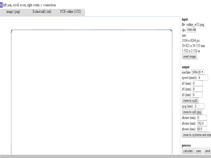
After completing from eagle side, I exported .png image of the design then by using basic steps to generate .rml files for traces, drills, and outline.
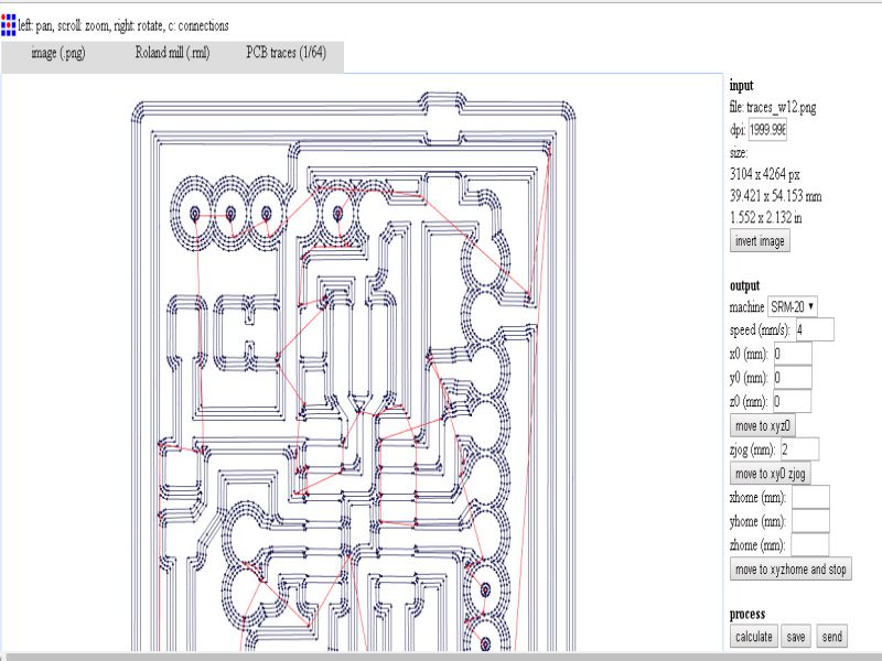
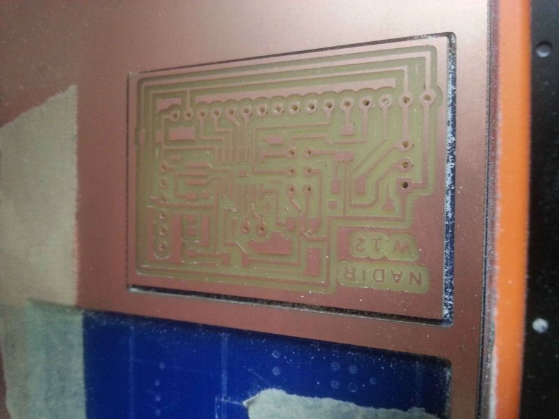
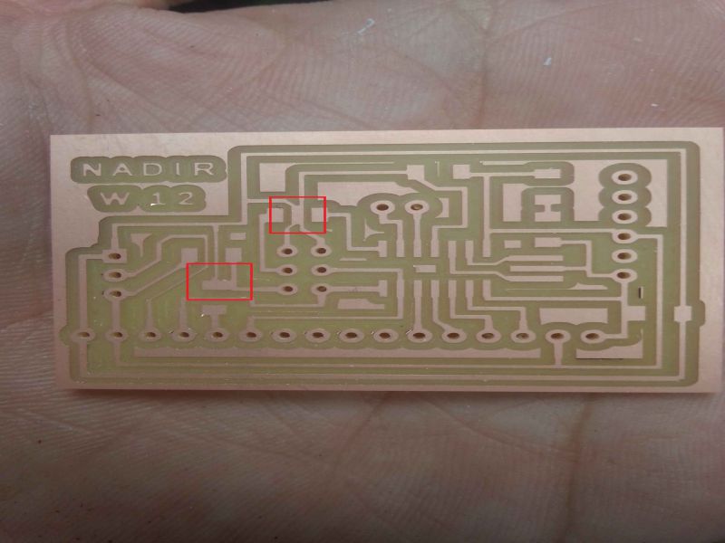
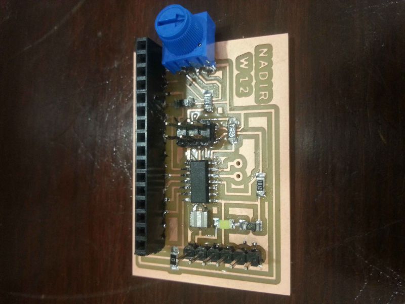
Here I got two connections which joined each other due to less empty space, so by getting rid from this problem, I disconnect wrong paths by using a cutter. In below images both parts are shown.
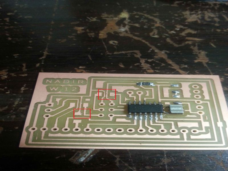
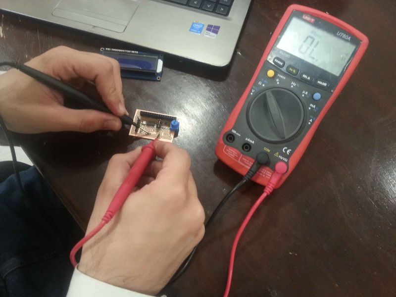
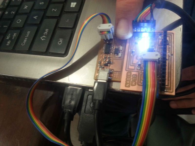
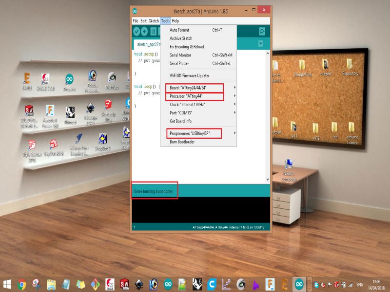
Now It is time to up the board by burning bootloader to microcontroller through ISP programmer. Below images shows successful completion of the burning bootloader in the circuit.
I upload the simple LCD code in arduino ide, it compiled and uploaded successfully, the code is written below:
#include "LiquidCrystal.h"const int rs = 5, en = 4, d4 = 3, d5 = 2, d6 = 1, d7 = 0;
LiquidCrystal lcd(rs, en, d4, d5, d6, d7);
void setup() {
lcd.begin(16, 2);
lcd.setCursor(6, 0);
lcd.print("NADIR");
}
void loop() {
lcd.setCursor(1, 1);
lcd.print("FABLAB KHAIRPUR");
}
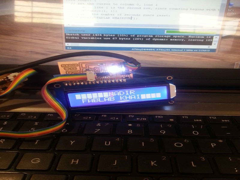
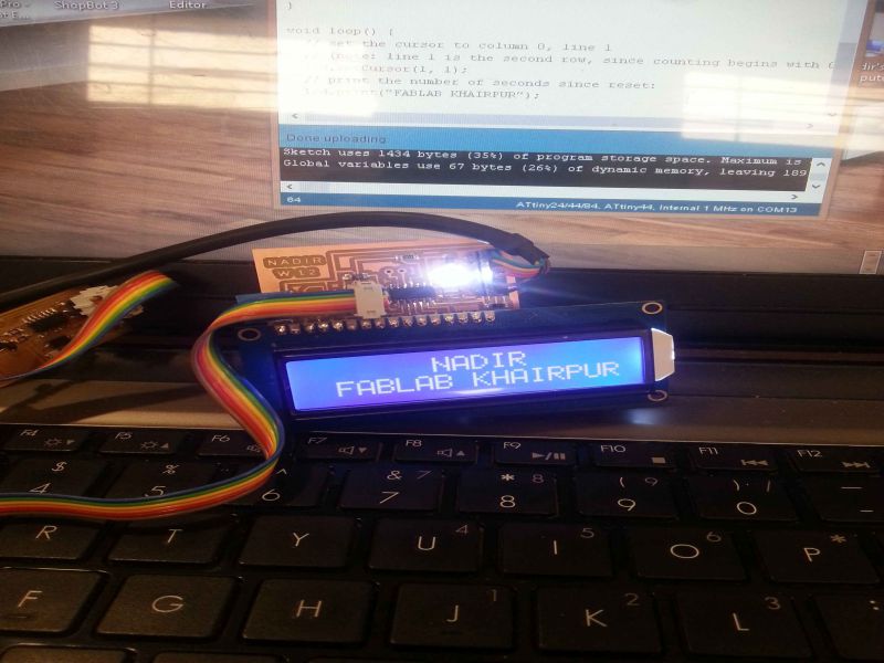
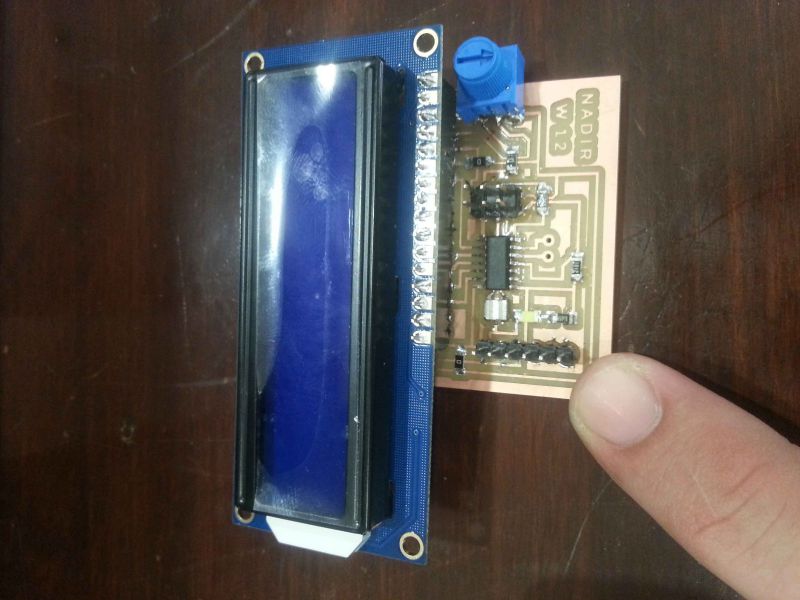
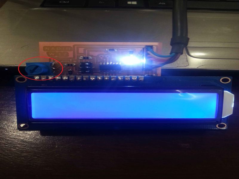
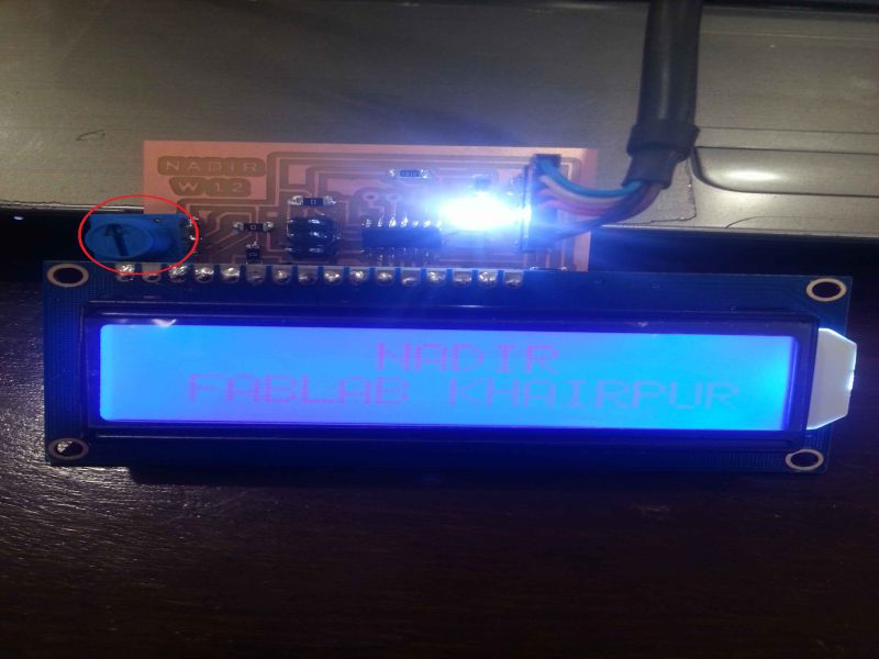
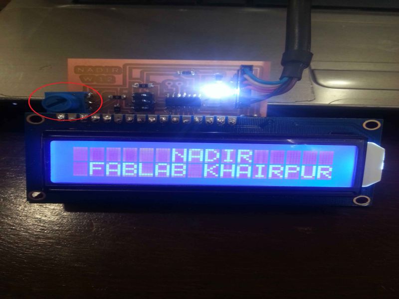
Below images shows that how brigtness is increased simply by varying the potentiometer
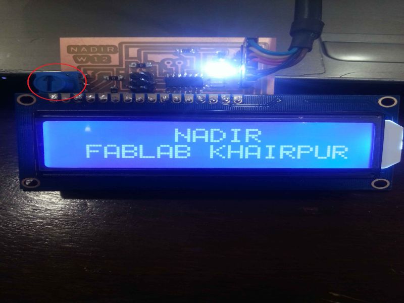
This was all about LCD interfacing with attiny44 on a single board, I enjoyed and learnt many undefinable things in this week. So, this is output device week, and I displayed the text on LCD by controlling it through a microcontroller 'attiny44'.
Download all files from here
This work is licensed under a Creative Commons Attribution-NonCommercial 4.0 International License.