Input&output device (Final Project )
For my final project, I used many input and output devices to make sure the system is working properly.
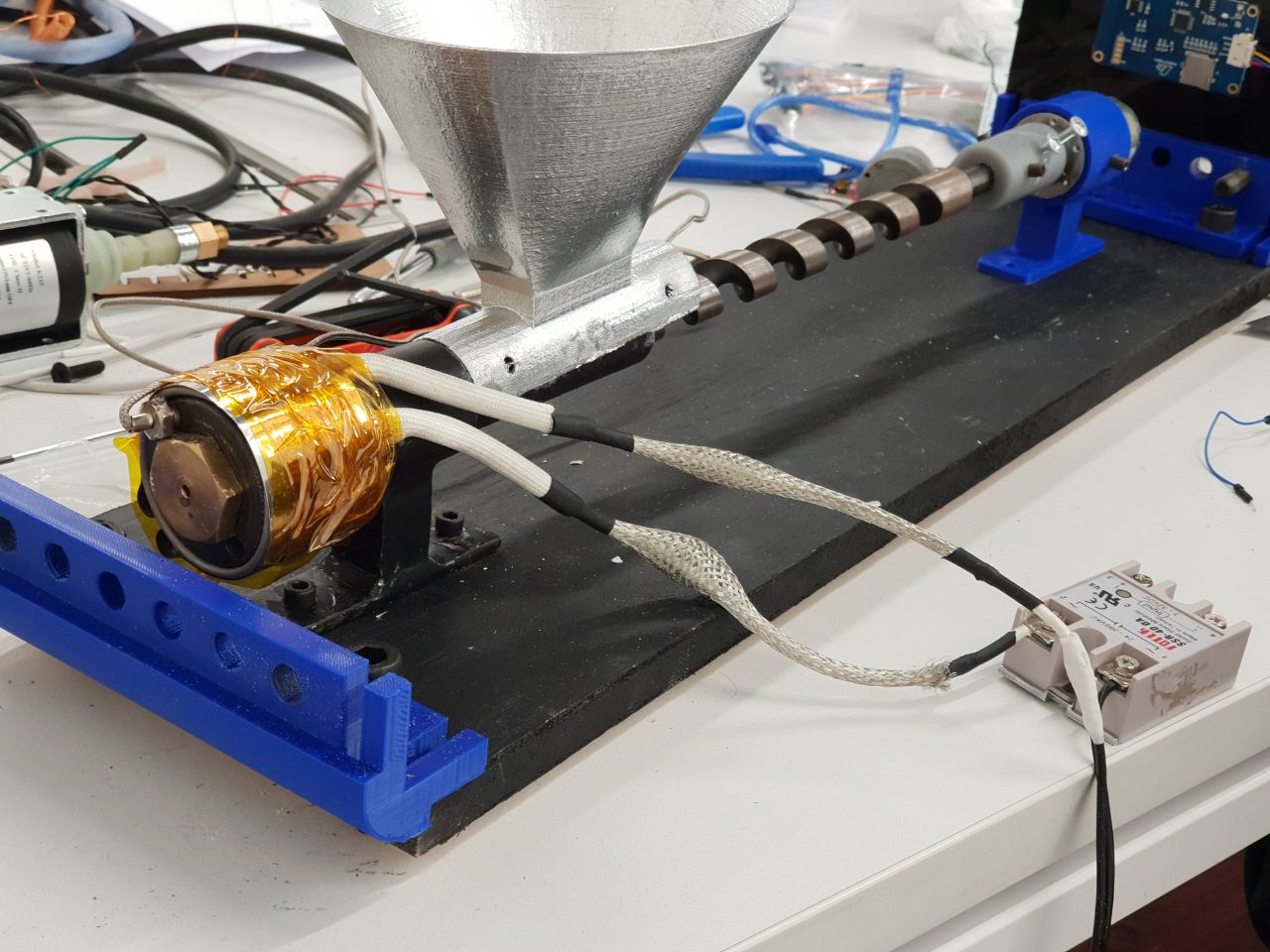
I used of course a DC motor that will move the extruder to push filament through the heated nozzle. I also used a heater as an output device to heat the nozzle and a thermocouple to sense the temperature as an input device.
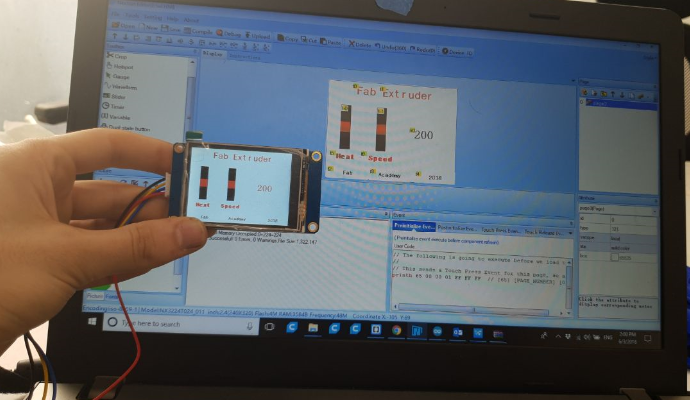
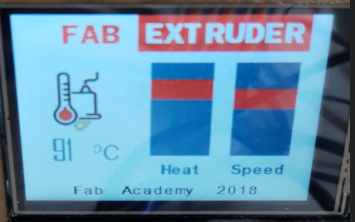
To be able to control the system, I used a really cool touch screen that doesn't only display the current speed of the motor and the temperature but also allows for the user to control the speed of extrusion and the temperature of the nozzle.

Greartisan DC 12V 15RPM Gear Motor High Torque Electric Micro Speed Reduction Geared Motor Eccentric Output Shaft 37mm Diameter Gearbox
(k) type thermocouple

Thermocouples have been around forever and are a great way to measure temperature. They have a very large range, are robust and come in all kinds of lengths, varying tip configurations and a variety sheaths. The challenge with using thermocouples is with the need for what is known as cold junction compensation and the need to detect a very small voltage change for every degree in change of temperature.
IMPORTANT NOTE_ Most K thermocouples come with a red lead and a yellow lead. The red lead is normally your negative connection and the yellow lead is your positive. That is industry standard. That said, some of the suppliers for the module will in fact jack this up and provide you a thermocouple with red indicating positive.

I decided to go with the K type because the temperature used for my final project will be around 200_250 degrees C and the K type can reach to 1260 degrees which will be more than enough moreover its design is very suitable with my design of the final project.
Fortunately there are chips like the MAX6675 that make connecting a thermocouple to your Arduino an affordable breeze. The device measures the output of a K Thermocouple and provides the result to the Arduino via a SPI interface.
/*
  // Sample Arduino MAX6675 Arduino Sketch

#include "max6675.h"            // Include the library used

int ktcSO = 8;
int ktcCS = 9;
int ktcCLK = 10;

MAX6675 ktc(ktcCLK, ktcCS, ktcSO);      // ktc is a function inside the library I specified the clk, CS and S0 pins of the amplifier


void setup() {
  Serial.begin(1200);
  // give the MAX a little time to settle
  delay(5000);
}

void loop() {
  // basic readout test

   Serial.print("Deg C = ");
   Serial.print(ktc.readCelsius());
   Serial.print("\t Deg F = ");
   Serial.println(ktc.readFahrenheit());

   delay(5000);}
Here is the first code and I have uploaded it to my arduino; at the beginning I faced a problem as I kept getting error as for some reason it didn't read the Port so I removed all the entries in the USB then it was able to read COM.
A heater. I will be using this heater for my final project to heat the extruder. This heater is custom made to fit on my extruder, I will talk about in details in my final project documatnation.
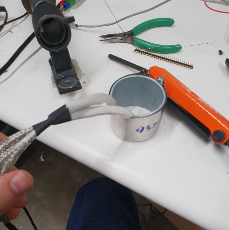

This heater operates on a 12V and I used a solid-state relay as seen above to be able to control the temperature.
I also used a K-type thermocouple to be able to get the reading from the heater just like I did last week.
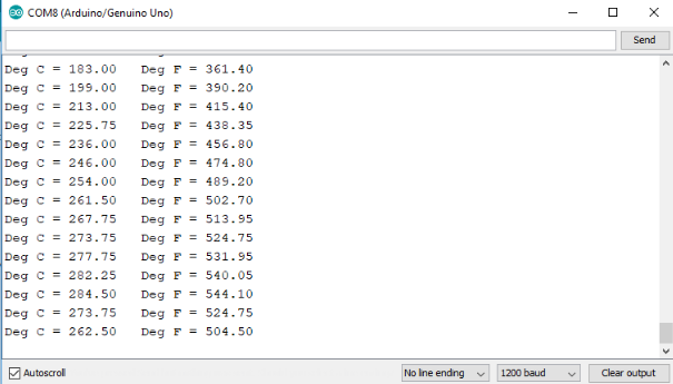
The above image shows the readings from the serial monitor. As you can see it managed to heat up to 260 degrees celsius which is more than enough for my filament recycling extruder. You can find my code below.
#include
  // Sample Arduino MAX6675 Arduino Sketch

#include "max6675.h"

int ktcSO = 8;
int ktcCS = 9;
int ktcCLK = 10;
#define LED_BUILTIN 7

MAX6675 ktc(ktcCLK, ktcCS, ktcSO);


void setup() {
  Serial.begin(1200);
  // give the MAX a little time to settle
  delay(5000);
   pinMode(LED_BUILTIN, OUTPUT);
}

void loop() {
  // basic readout test
  digitalWrite(LED_BUILTIN, HIGH);   // turn the LED on (HIGH is the voltage level)
//  delay(1000);                       // wait for a second
//  digitalWrite(LED_BUILTIN, LOW);    // turn the LED off by making the voltage LOW
//  delay(1000);
   Serial.print("Deg C = ");
   Serial.print(ktc.readCelsius());
   Serial.print("\t Deg F = ");
   Serial.println(ktc.readFahrenheit());

   delay(5000);
   }
Greartisan DC 12V 15RPM Gear Motor High Torque Electric Micro Speed Reduction Geared Motor Eccentric Output Shaft 37mm Diameter Gearbox
// connect motor controller pins to Arduino digital pins
// motor one
int enA = 10;
int in1 = 9;
int in2 = 8;

void setup()
{
  // set all the motor control pins to outputs
  pinMode(enA, OUTPUT);
  pinMode(in1, OUTPUT);
  pinMode(in2, OUTPUT);
}

//
//}
void loop()
{
  digitalWrite(in1, 0);
  digitalWrite(in2, 1);
  analogWrite(enA, 500);
delay(5000);

   digitalWrite(in1, 1);
  digitalWrite(in2, 0);
    analogWrite(enA, 500);
delay(5000);

}
Here is my code

In this code I first programmed the motor to turn in one direction giving in1 a value of zero and in2 a value of 1 and the set the speed by giving the pwm value of 500 to the enable.
Then I reversed the direction of the rotation by flipping the values of in1 & in2.
As you can watch in the video the lead screw is moving .
s
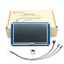
Nextion LCD Touchscreen Tutorial for Arduino
The Nextion LCD touchscreens are great for Arduinos because most of their functionality and processes are self contained in the screen. The communication with an Arduino is via a Serial UART port. The benefit is that the Arduino does not use a lot of resources or pins dealing with a high resolution touchscreen it simply sends serial commands to the screen or receives event notifications such as button presses.
Hooking up a Nextion LCD to an Arduino UNO
Connect +5V to 5V on the Arduino
Connect TX to pin 2 on the Arduino
Connect RX to pin 3 on the Arduino
Connect GND to GND on the Arduino
Note that the 4.3" version consumes up to 250mA, the 2.4" model up to 90mA. Both are well within the specs of the Arduino UNO's 5V regulator (450mA).
Installing Firmware via an SD Card
For this first part of the tutorial we are going to be using a firmware that demonstrates a couple of buttons, a progress bar and a text field.
NOTE: The older .tft files are not compatible with the latest firmware. Please load the .HMI source files into the Editor, compile and use the newly generated and upgraded .tft files in the example below.
In the firmware folder in the library you will find the .tft files:
2.4 Nextion display 240x320Example.tft
4.3 Nextion display: 272x480Example.tft
Copy the .tft file to a FAT32 formatted SD Card. Ensure that there is no other .tft file on the SD Card
Insert the SD Card into the slot and power cycle the display
The display should immediately begin to install the firmware
When the software is installed, remove the SD Card and power cycle the display again
The following image should appear on the screen