Input&Electronics Design &Production (Final Project )
This is my final project board which is the Fab Extruder. This board will control a DC motor that will push the shreaded platic into a heated nozzle. The board will also control the heater responsible for heating the nozzle all while displaying the status on the screen as well as take an input from the user to control both the speed of the motor and the temperature of the nozzle.
The components I wil use are:
1. Atmega328P Chip as the microcontroller.
2. MOSFET with a diode to drive the motor.
3. Voltage regulator to convert the voltage from 12V to 5V.
4. MAX6675 thermocouple K-type.
5. Crystal 16MHz.
6. Reset Button.
7. LED with a resistor.
8. 2x 22PF capacotors.
9. 5x Terminals.
10. Pin headers for programming purposes.
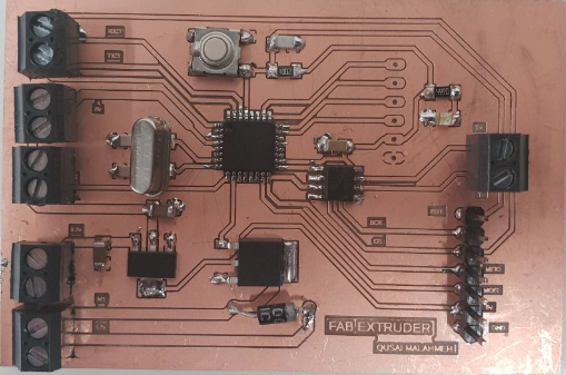
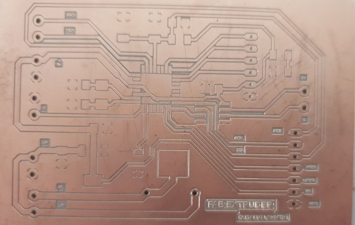
I am using atemga328P as the microcontroller to control my fab exrtuder. As you can see, I use lables to make it easier for me to track each signal.
I added a reset button to the board, just in case I needed it. I also added the 100nF capacitor and 10K Ohm resistor to be able to program my board using the FTDI cable.
I used a voltage regulator to drop the voltage down from 12V to 5 V since I'm using a 12V power adapter to power my board. I also added an LED connected between the VCC and the ground to indicate when my board is powered on.
I connected the max6675 K-type thermocouple to my board directly instead of using a ready module. As seen in the above photo.
I added a protection diode and MOSFETT from the power adapter of 12V to my voltage regulator. In normal conditions this diode is forward biased, under reverse battery conditions, the diode becomes reverse-biased and no current flows which will protect my board from damage.
These are the pin headers I used to connect the motor, the power supply, the thermocouple and a relay to control the heating.
Production
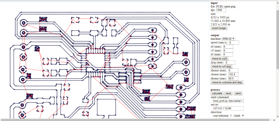
After I finished routing my connection and was happy with how it looked, I imported it as an image and used Fab modules to set the milling settings.
The aboce photo shows the settings for the inner traces. I used a 0.2mm tool to mill the board, with 4 passes, speed of 4mm/s and a cut depth of 0.5mm.
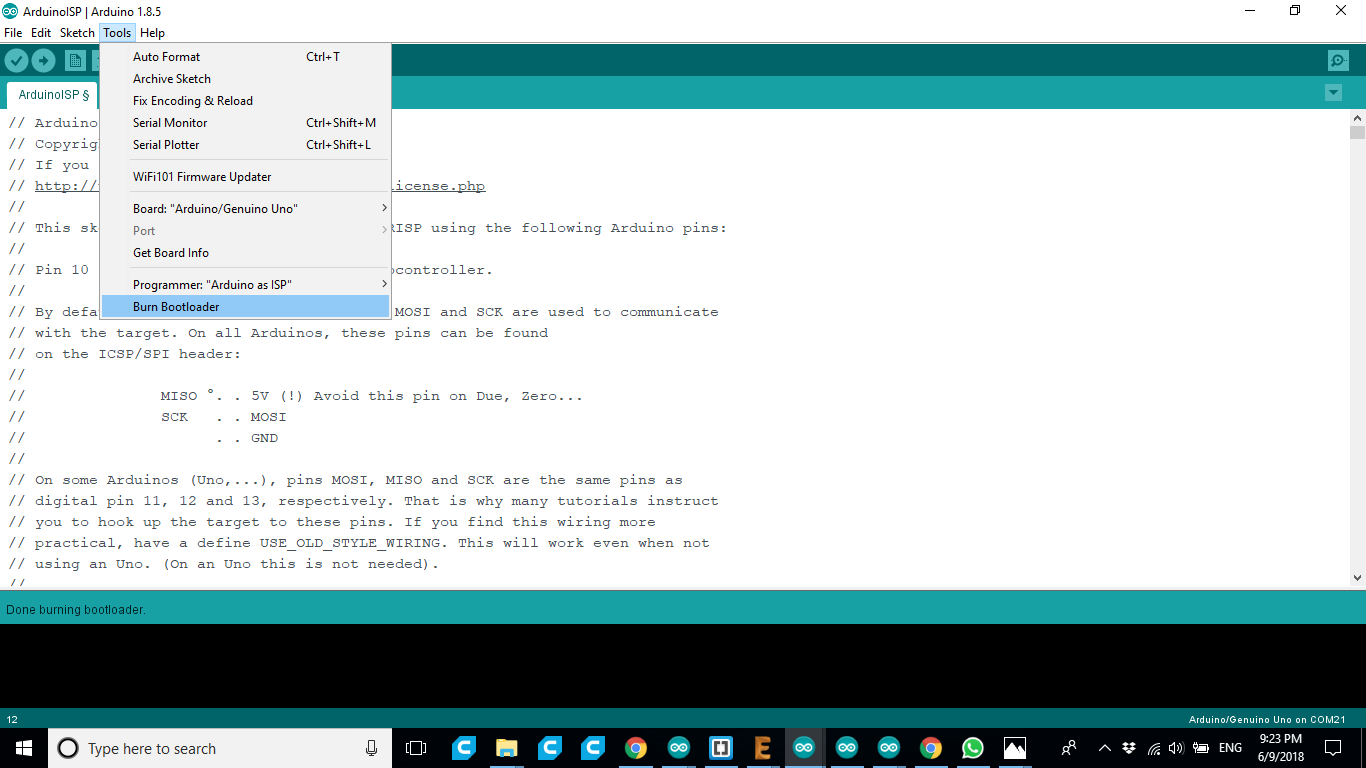
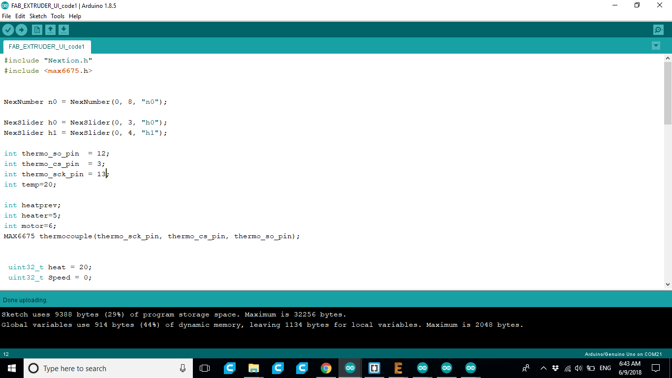
The above photo shows a snapshot of when I uploaded the code to my board.
#include "Nextion.h"
#include <max6675.h>

'[[[p
"

NexNumber n0 = NexNumber(0, 8, "n0");

NexSlider h0 = NexSlider(0, 3, "h0");
NexSlider h1 = NexSlider(0, 4, "h1");

int thermo_so_pin  = 12;
int thermo_cs_pin  = 3;
int thermo_sck_pin = 13;
int temp=20;

int heatprev;
int heater=5;
int motor=6;
MAX6675 thermocouple(thermo_sck_pin, thermo_cs_pin, thermo_so_pin);


 uint32_t heat = 20;
 uint32_t Speed = 0;

NexTouch *nex_listen_list[] =

{

    &h0,
    h1,

    NULL

};&


void setup()
{
pinMode(heater, OUTPUT);
pinMode(motor,OUTPUT);
    nexInit();
}
void loop()
{

  temp=thermocouple.readCelsius();

    h0.getValue(&heat);
     h1.getValue(&Speed);
      delay(100);

if(heat==heatprev){
    n0.setValue(temp);
    heatprev=heat;
}
else {
  n0.setValue(heat);
   heatprev=heat;
}

    nexLoop(nex_listen_list);
      delay(100);


if(temp<heat){
  digitalWrite(heater,HIGH);
}
else if(temp >heat+5){
  digitalWrite(heater,LOW);
}

if (temp>heat){
  analogWrite(motor,Speed);
}

else if(temp<heat-5) {
  analogWrite(motor,0);
}

}
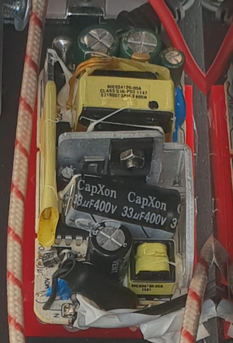
To power my device, I used a 12V Power adapter but I deassembled it.
I connected the 220V part to the relay that controls the heater and the 12V output to my board that regulates it to 5V to the parts that need it.