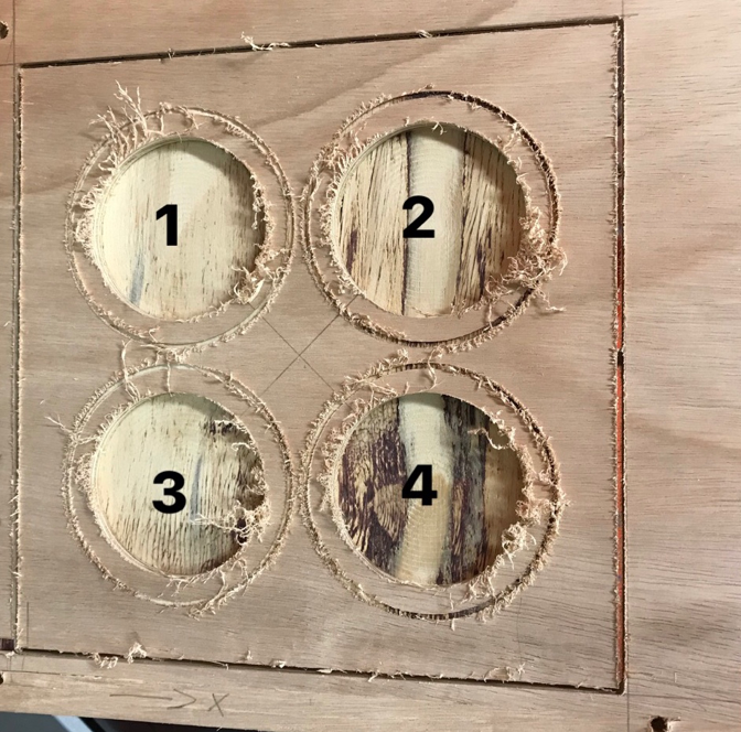
- Test runout, alignment, speeds, feeds, and toolpaths for your machine.
To make something
big, I decided to use the CNC router machine. A CNC router is a machine
that uses a cutting bit that rotates at a very high speed to remove
material from a part. The machine reads a pre‐programed computer file
telling it where and how to cut. A cutting bit is rotated at a very
high RPM by a spindle motor, which can move the bit up and down. This
mechanism is moved left, right, front, and back by a cross arm. The
machine is therefore known as a three‐axis router because it can move
on the XY & Z axis. The machine can do two dimensional cutouts and
etching, as well as three‐dimensional relief work. You can cut MDF,
plywood, solid wood, foam, plastics and soft metals (like aluminum)
using this machine. The thickness of the material should always be
measured using a Vernier caliper.
When you make your design, be sure to leave at least an inch(2-3cm)
around the perimeter of the material. You will need to screw the
material to the bed of the ShopBot and you do not want the cutter to
hit the screws. The free space between the pieces will depend on the
diameter of the cutter you use as well (Thumbs up rule is to leave
around 1 inch). It is always better to use more material rather than
less.
File Formats:
2D Design 3D Design
a.
Svg
a. STL
b.
DXF
b. OBJ
c. AI
d. PDF
Up Cut vs. Down Cut Router Bits:
Choosing between up or down cut router bits is one of many things in
woodworking that can be frustrating, until, the reasoning behind the
design difference is understood a little better.
Check out this tutorial:
http://www.newwoodworker.com/updowncutbits.html
Up Cut Bits- Up cut bits are very efficient at evacuating chips from
the hole or slot it is cutting. When the router is oriented with the
bit up, as when mounted on a router table, the side of the bit closest
to the operator is turning counter clockwise (left to right) and the
back side clockwise (right to left).
Down Cut Bits- The downward slicing action of a down cut bit leaves a
very clean, crisp edge around the hole or groove it cuts. While chips
still are evacuated from the hole, a down cut bit is far less efficient
in this respect than is an up cut design. The bit rotation is
clockwise. The side of the bit farthest from the operator is turning
counter clockwise(left to right) , the near side clockwise (right to
left). This is very important for feed direction, as you always want the
cutting edges turning against the feed direction, not with it.
(Down Cut Left - Up Cut Right)
After I familiarized better with the CNC router, I started to think
what I could design. I went to a shopping mall this past week and I saw
a table to use your computer while you are lying down in your bed. I
really needed one because I like to write some assignments in bed and
my back and neck hurts after a while because, of the position I am
working in. So, based on that I decided to make a computer desk that, I
could use when I lay down in my bed.
SolidWorks:
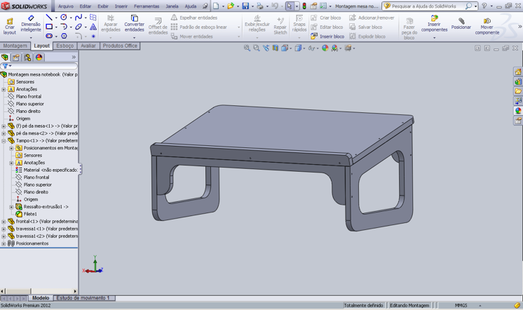
I used Solid Works to design my table (I create the four pieces
separately to more accurately design each part) as you can see in the
images below:
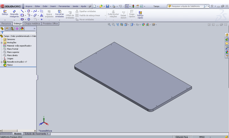
First I designed the cap: 600 mm x 320 mm
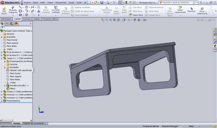
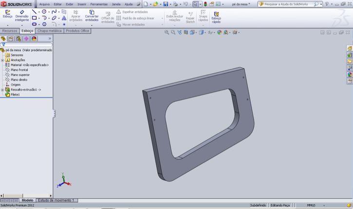
Then I designed the feet support, which by the end I duplicated, because I needed two parts: 250 mm x 300 mm
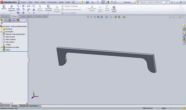
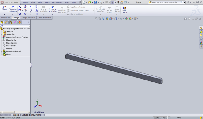
After that I designed the support piece and then I duplicated it as again I needed two parts: 570 mm x 100 mm x 40 mm
Finally I designed the piece that is going to hold my computer, since the table is a little inclined: 600 mm x 30 mm
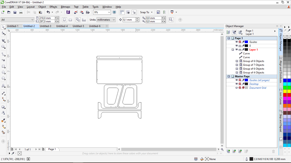
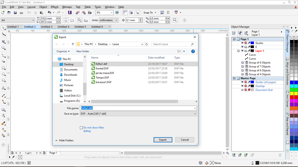
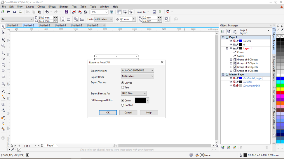
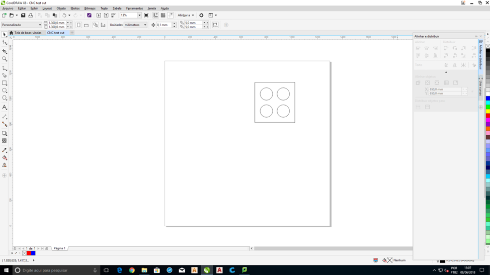
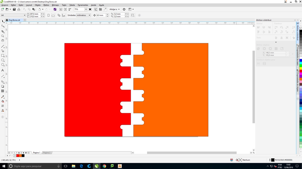
CorelDRAW & ArtCAM:
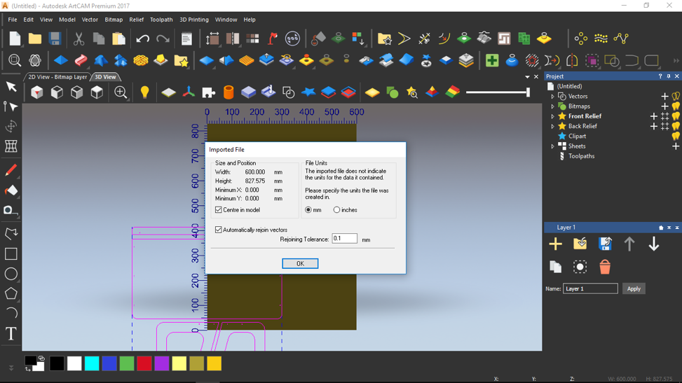
After this I saved the file and needed to transfer the file to
CorelDRAW first and then to ArtCAM. I opened my model on CorelDRAW to
rearrange the drawings and then to save the image in .dxf format.
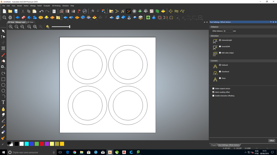
ArtCAM is used to generate the appropriate tool-paths for machining the
surface relief created. This software will also generate a code that
the CNC router will be able to read and initiate the command.
Click the links bellow to learn how to get started using ArtCAM, use its tool functions and how to access them:
http://help.autodesk.com/view/ARTC/2018/ENU/?guid=GUID-A65C8FFF-9DC1-499A-9560-C58704ED92C0
(Recommend searching the entire website before getting started as it was a very useful tool)
http://saap.unm.edu/documents/fablab/cnc-operation-instructions.pdf
Steps
ArtCAM steps from the ArtCAM website above:
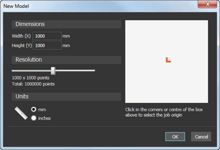
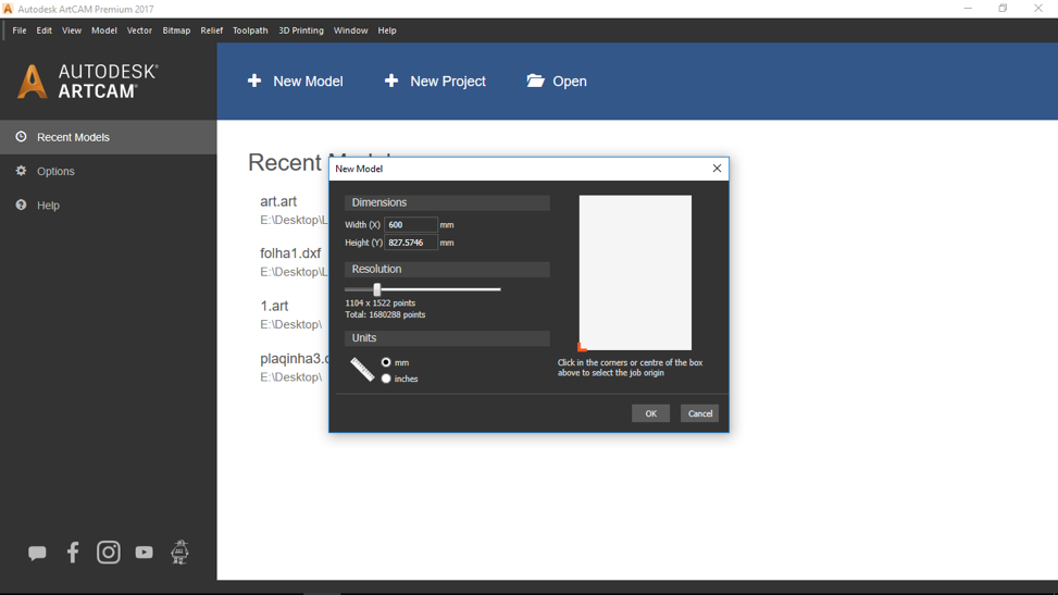
The first step is to create a new project and create new model:
1. On the start screen, click
New Model. The
New Model dialog is displayed.
2. Select the
Units in which you want to work. For my project I used mm.
3. Enter the
Width (X) and
Height (Y)
of the model. The white box shown in the dialog is updated to represent the shape of the
sheet of material.
4. Click and drag the slider to specify the model's
Resolution. The number of pixels is updated.
5. Click the centre or a corner of the
white box to specify the model's origin. The position of the origin
icon

is updated.
6. Click
OK to create the model. The dialog closes and ArtCAM switches to display the model screen.
Create vectors For Your 2D or 3D Model:
The next step is to create vectors for your 2D or 3D model.
Vectors: are
types of images. They are made of simple lines, which consist of nodes
linked by spans. Use vectors to create 2D shapes, from which you can
create 2D machining toolpaths or create reliefs.
You can draw standard geometric shapes such as arcs, circles, ellipses,
polygons, rectangles, squares, and stars. You can also use vector tools
to create free-form shapes using polylines and you can also create
vector texts as well.
Creating a geometric shape:
1. Select
Vector > Create, and then the name of the geometric shape you want to create, for example,
Rectangle. The cursor
changes to

and the
Tool Settings panel for the vector shape is displayed.
2. Click and drag the cursor to
specify the size of the shape, or to specify the distance between the
start and end points if creating an arc.
3. Release the mouse button.
4. If you are creating a star
shape, move the cursor to specify the radius of the star's inner
circle, then click.
5. If you are creating an arc,
move the cursor to specify the radius of the arc, then click.
6. Right-click to create the vector. The
Tool Settings panel closes.
Editing and Manipulating Vectors by Editing Their Nodes and Spans:
1. Select the vector. The vector is displayed in pink and surrounded by a bounding box.
2. Select
Vector > Node Editing or click the
Node Editing 
button. The
Tool Settings: Node Editing panel is displayed and the cursor
changes to

to indicate node-editing mode is enabled. If you are editing a vector that uses linear spans, nodes are displayed. If you
are
editing a vector that uses arc or Bézier-curve spans, nodes and control
points are displayed.
3. To hide the control points, select the Maintain smooth curves check box in the panel.
4. To reposition a node:
a. Position the cursor over the node.
b. When the cursor changes to

, click and drag the node to its new position. The spans either side of the node are updated.
c. When you have finished repositioning the node,
release the mouse button.
5. If you are editing a vector
that uses arc or Bézier-curve spans and want to edit the spans either
side of a node:
a. Position the cursor over one of the
node's control points.
b. When the cursor changes to
, click and drag the control point. The spans either side of the node are updated.
c. When you have finished editing the spans, release
the mouse button.
6. To add a node point mid-way between two existing nodes:
a. Select the
Display virtual mid-points check box. Mid-points are displayed along the spans between the nodes.
b. When the cursor changes to
, click the span. ArtCAM creates a node and displays the mid-points along the
spans between the new node and its adjacent nodes.
c. Position the cursor over a mid-point.
7. Close the panel to disable node-editing mode.
Transform Vectors:
How to transform vectors by changing their scale, position, orientation, and shape.
1. Select the vector. The vector is displayed in purple and surrounded by a bounding box.
2. Select
Edit > Transform or click the
Transform 
button. The
Tool Settings: Transform panel is displayed.
3. To resize the vector:
a. Position the cursor over a red handle

.
b. When the cursor changes to

,

,

, or

, click and drag
. The
Width and
Height in the panel are updated.
c. When you have finished resizing the vector,
release the mouse button.
4. To reposition the vector:
a. Position the cursor over the vector.
b. When the cursor changes to

, click and drag the vector to its new position. The
X,
Y,
 X
X, and
Y values in the
panel are updated.
c. When you have finished repositioning the vector,
release the mouse button.
5. To rotate the vector:
a. Position the cursor over the green
handle

.
b. When the cursor changes to

, click and drag
. The rotation angle in the panel is updated.
c. When you have finished reorienting the vector,
release the mouse button.
6. To shear the vector:
a. Position the cursor over a pink handle

.
b. When the cursor changes to

, click and drag
. The
W and
H angle values in the panel are updated.
c. When you have finished shearing the vector,
release the mouse button.
7. When you have finished transforming the vector, close the panel.
Creating Tool Paths:
The next step is to create tool paths.
Toolpaths: are paths along which a tool follows when manufacturing a product. Different toolpaths are available depending on how
and what you are machining.
ArtCAM has many 2D and 3D machining toolpaths to machine 2D and 3D
shapes from vectors. The toolpaths functions for 2D and 3D machining
are slightly different while they also share many of the same tools.
After creating the toolpaths, one can simulate them to see if the paths
are correct (recommended more for 3D Toolpaths). The various functions
one will need for working with toolpaths can be easily accessed through
the
Toolpaths panel. To display the panel, select the
Toolpaths item in the Project Tree.
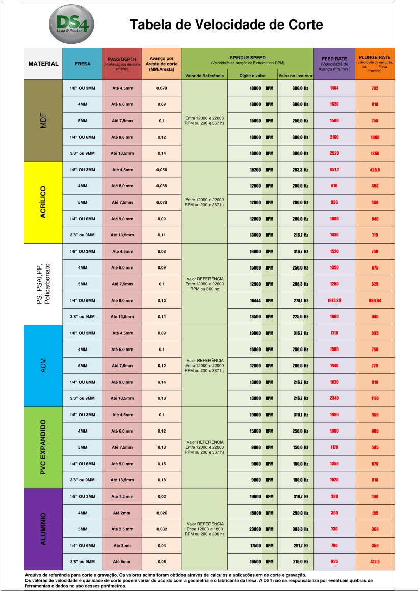
When creating a machining toolpath, you must specify:
• the thickness of the sheet or block of material
from which the product is to be manufactured
• the extent of the toolpath
• the tools with which you want to
machine the product (drill bits/size and machine), including the tools'
settings, such as
stepover and stepdown
distances, feed and plunge rates, spindle speeds, bridges and clearance
strategies.
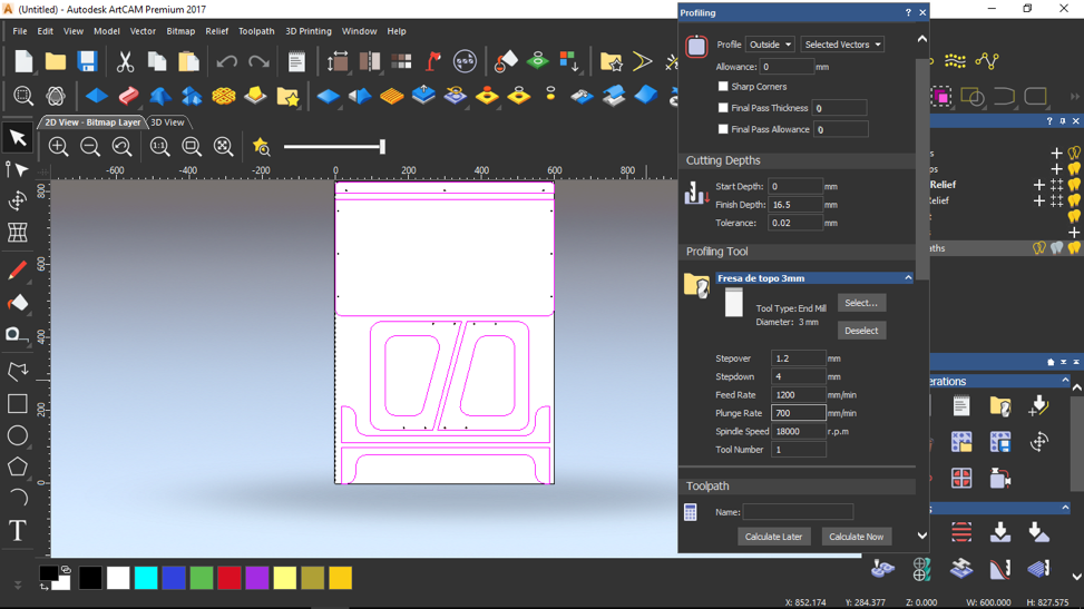
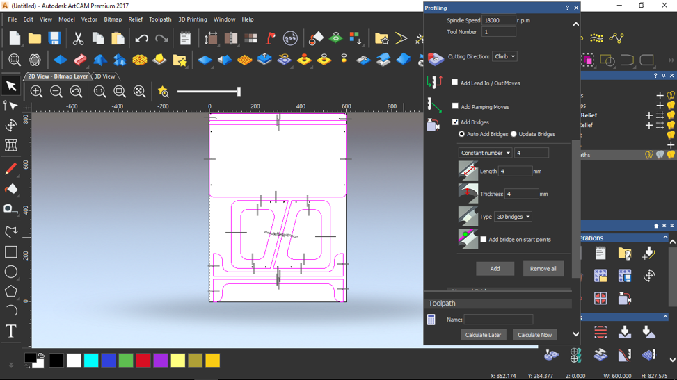
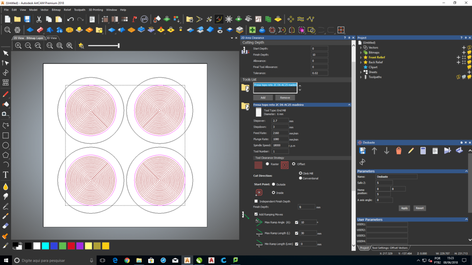
Adjusting machining parameters when creating a Toolpath:
1. In the
Toolpaths panel, click the toolpath you want to create.
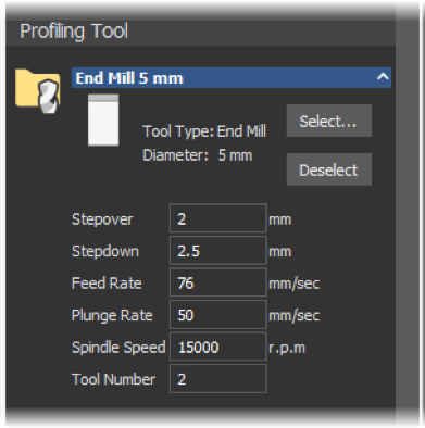
2. When you have selected a tool,
click the tool's control bar to display the machining parameters.
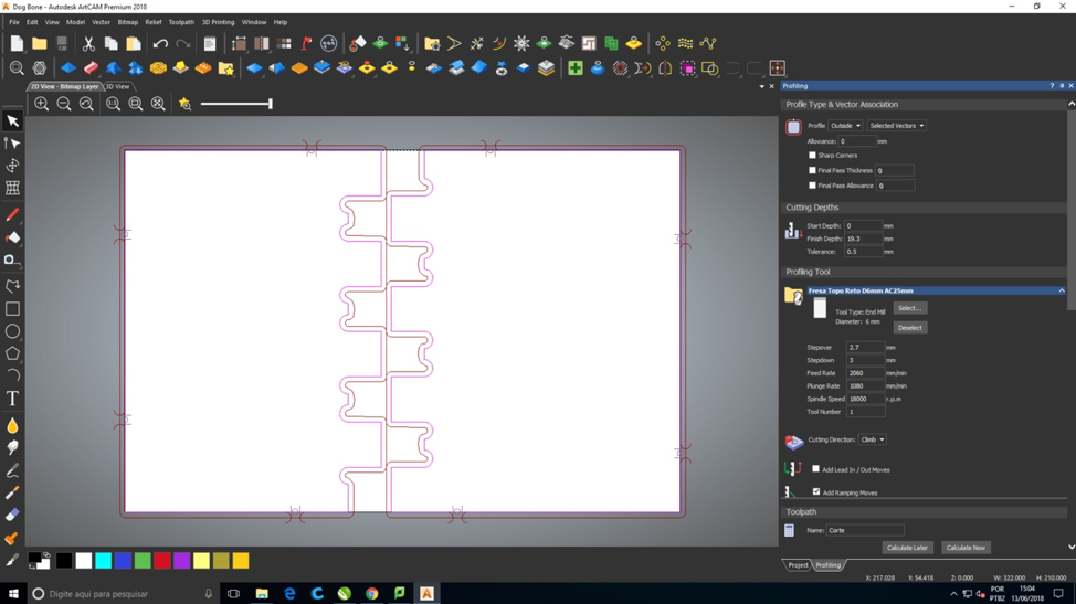
For example, if you have selected a 5mm End Mill tool in a
Profiling toolpath, the tool area of the
Profiling panel is as follows:
3. You can now set the new machining parameters:
Stepover distances:
distance the tool will move horizontally when making the nex pass.
Value can determine the resolution of the cut and will affect the rate
in which your material will be cut in the X axis. So as the tool moves
back and forth across your material it does this in increments. The
smaller these increments the less visible the machine lines and cut
paths.
Stepdown distances:
distance the tool will move vertically when performing the next Z-pass.
A very important value. The value determines how far “in the Z axis”
the machine will cut during each pass. If your STEPDOWN is set at .5”,
then the first pass will cut into your material .5”. For more accurate
cuts, in more dense materials, the lower the STEPDOWN will ensure that
there is less resistance on the tool and therefore a cleaner, more
accurate cut.
Feed rate:
will either slow or speed up the rate at which the machine head moves
in the Y axis. Affects both the speed and resolution of your cut.
Plunge rate:
will determine the rate in which the tool will “plunge” in the Z axis.
This value can potentially be used to reduce resistance on the tool tip
and therefore. used when drilling.
Spindle speeds:
is the speed with which the bit is rotating. At times it may be
applicable to increase or decrease this value according to the type of
wood, or other material you are cutting.
Clearance: allows you to cut reliefs into you material. You can cut a shape into your material without cutting all the way through it.
Bridges: is
a precautionary measure to prevent profiled vector artwork from
shifting in the material block as it is machined. Bridges exist on the
vector rather than on the toolpath, and you can add bridges to the
vector, either before, during, or after calculating a profile pass.
Start Depth: depth (Z) from the surface of the material at which you want to begin machining
Finish Depth: depth (Z) for the tool.
Tolerance:
specifies how closely the tool follows the shape of the selected
vectors. entering excessively small values increases the size of the
toolpath file and slows down calculation and machining times
Tool number: number you want to assign to the selected tool
Cutting Direction: cutting direction of the tools used for machining. Two options either conventional or climb milling.
Lead in/out moves:
are used to prevent the tool from marking the final profile when it
first comes into contact with the profile and at the end when it leaves
the profile.
Ramping moves:
allows the cutting tool to enter the block of material gradually,
ensuring minimum tool damage and reducing the likelihood of gouging.
For cutting out pieces of your material without cutting all the way
through material.
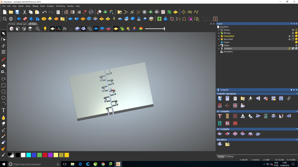
Simulate Tool Paths:
Then simulate your tool paths.This step is to help visualize the
machining process and the resulting surface finish. I found this step
extremely useful because it helped me understand the machining process
much better.
How to simulate your tool paths:
1. Then simulate your tool paths In the Project Tree, select the
Toolpaths item. The
Toolpaths panel is displayed.
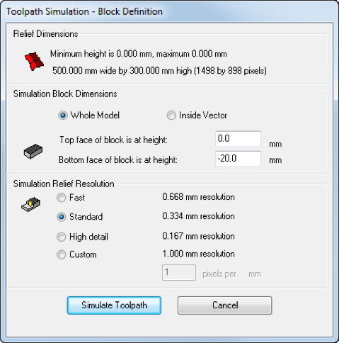
2. In the
Simulation area, click the
Simulate All Toolpaths 
button. The
Toolpath Simulation -
Block Definitiondialog is displayed,
for example:
3. Choose how much of the toolpath you want to simulate. Select:
•
Whole model to simulate the entire model; or
•
Inside vector to simulate part of the model within the selected vector.
4. Choose the resolution for the simulation. Select:
•
Fast to use a low resolution which, reduces the quality of the simulation but increases the speed.
•
Standard to use a resolution that compromises between the quality of the simulation and the speed
•
High detail to use a high resolution, which increases the quality of the simulation but reduces the speed.
•
Custom to specify a resolution.
5. Click
Simulate Toolpath. ArtCAM simulates the machining passes and adds a
Simulation item to the Project Tree.
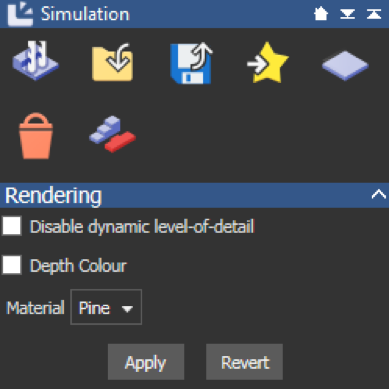
6. In the Project Tree, select the
Simulation item. The
Simulation panel is displayed.
7. To visualize the machined relief in the
material from which it is to be manufactured, select a Material in the list, then click
Apply.
8. If you are cutting the relief out from a block of material, click the
Delete Waste Material 
button and then click
OK.
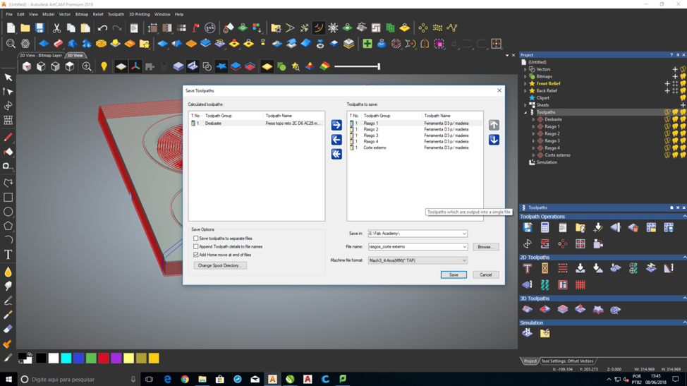
Save the Toolpaths:
After you have created and or simulated the
toolpaths, you must save the toolpaths as machine-specific files so you
can export the data to the CNC machine tool.
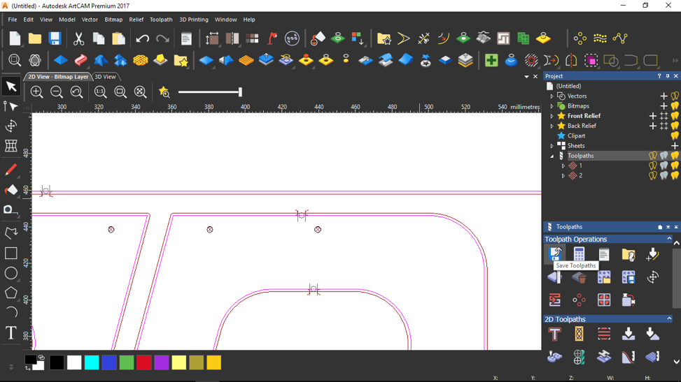
To save all toolpaths within a model:
1. In the Project Tree, select the
Toolpaths item. The
Toolpaths panel is displayed.
2.
In
Toolpath Operations area, click the
Save Toolpaths 
button. The
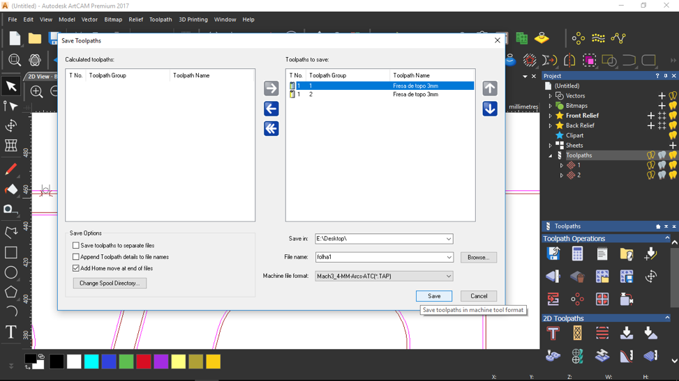
Save Toolpaths dialog is displayed,
3. Use

and

to order the toolpaths.
4. Specify the folder in which you want to save the file:
a. Click
Browse. The
Browse dialog is displayed.
b. Select the folder.
c. Click
Open. The dialog closes and the path is displayed in the
Save in box.
5. Enter a
File name.
6. In
Machine file format list, select file type for the machine tool.
7. Click
save.
8. Close the dialog.
9. Save file to pen drive
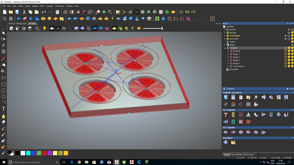
I then opened the ArtCAM and did all the steps that I explained
at the top of the page. I used 18mm wood form my sheet material.
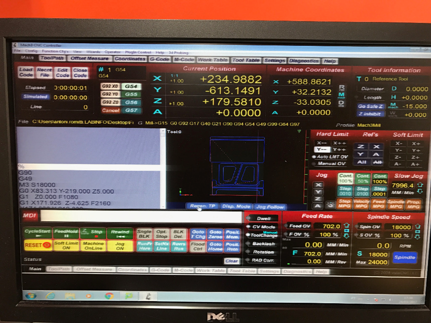
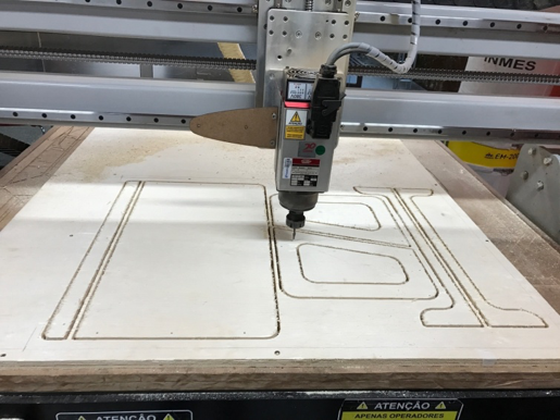
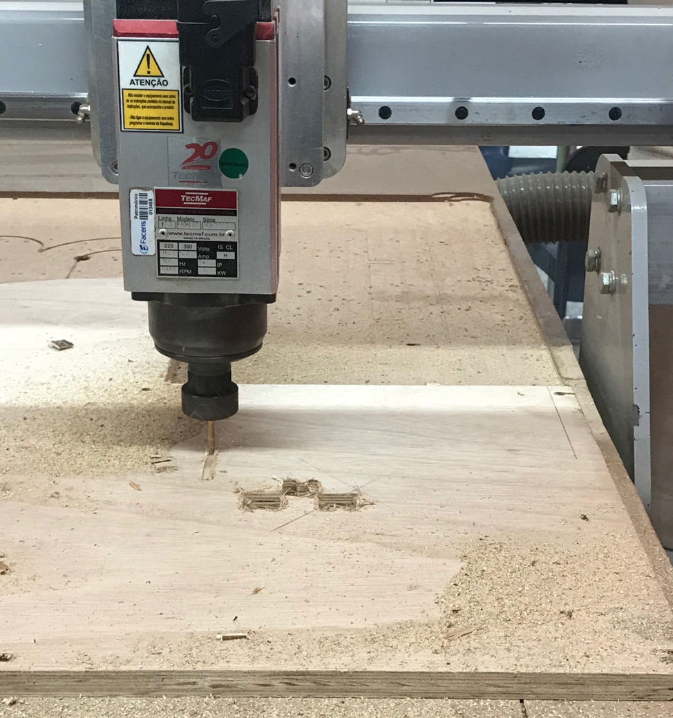
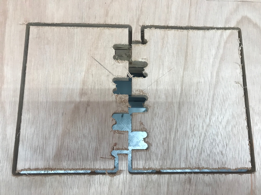
Cutting The Object
The machine I used was the DS4 Raptor model 1313.
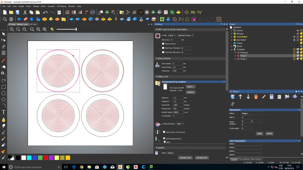
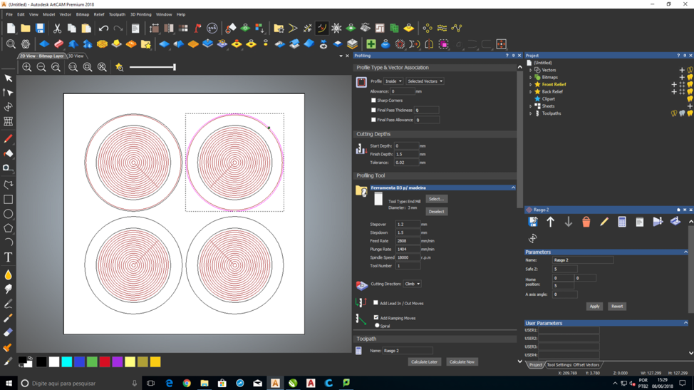
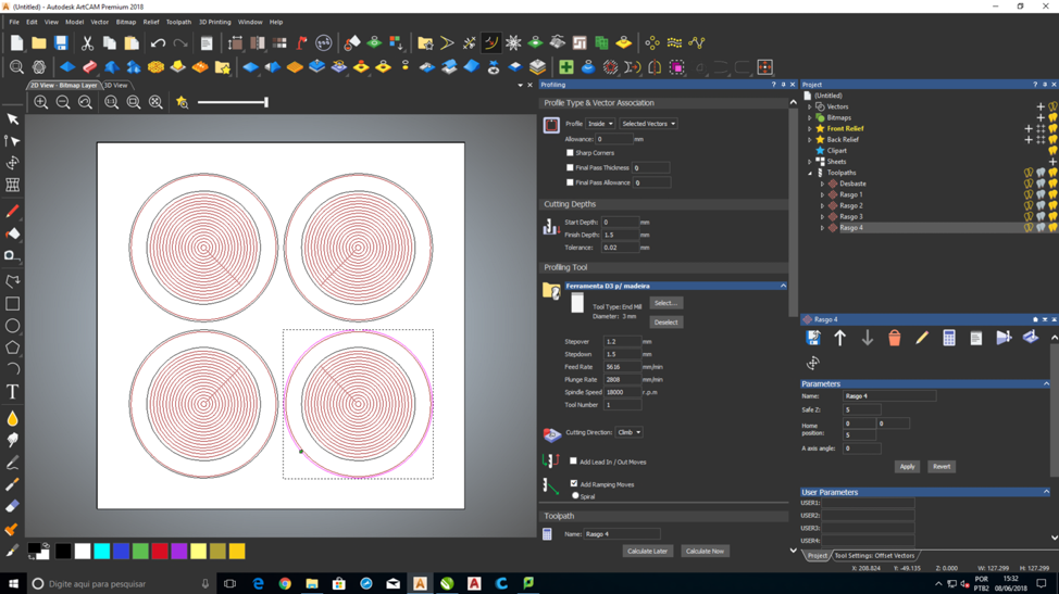
As you can see in the above picture, I used ArtCAM to set up the 3
toolpaths (outline, inside and holes for drilling). I used the 3mm tool
for all the toolpaths.
Here are some important parameters:
-The table area is 1300 x 1300 mm.
-The z axis maximum is 200mm.
-There are 3 axis on which the machine can move, they are X,Y and Z.
-The Z axis moves at the speed of 10.000mm/min.
Safety Tips:
Most machines that we use at Fab Lab can cause significant bodily harm
if safety measures are not taken into account. Below is a list of
safety tips:
• Always remain with the machine while it is running,
and be ready to hit the spacebar to pause the file, or the stop button
to stop the machine
in case of an emergency.
• Always wear eye protection while the machine is running, and have long hair tied back.
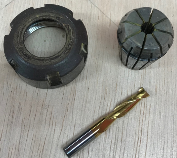
• When changing the endmill, disengage the spindle.
• Use the dust guard.
• Don’t use gloves.
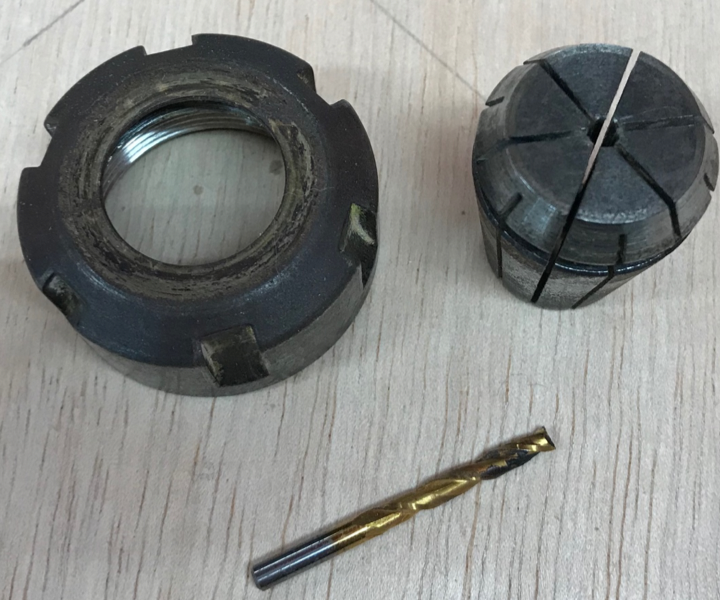
• Caution: Keep collets clean, a piece of debris or
dust between the collet and bit can cause the bit to spin elliptically,
harming bit, part or even
or even operator.
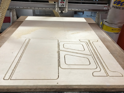
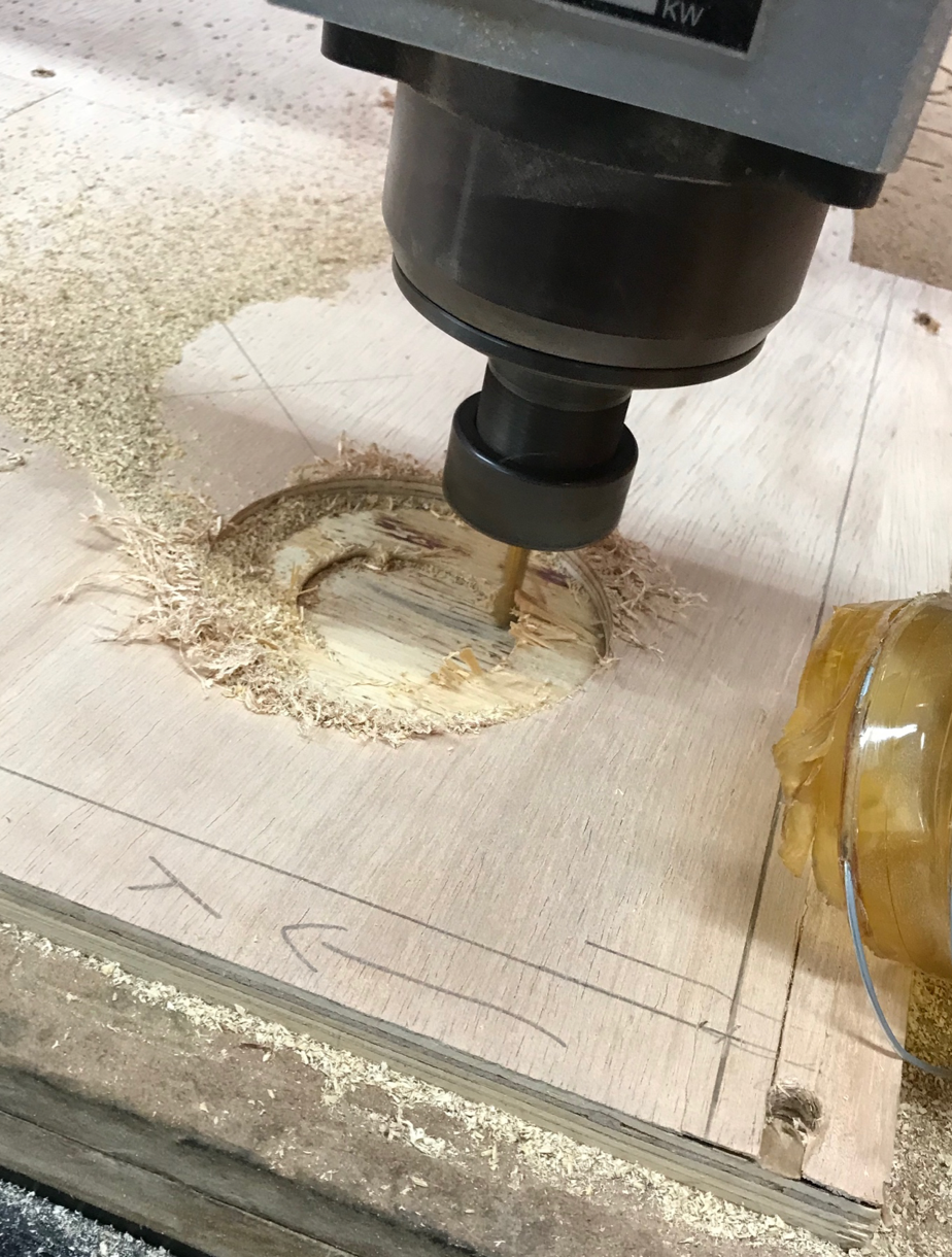
After that I placed the material on the table, I opened the file in the
computer that works with the CNC router and I positioned the X, Y and Z
axis using the “Jog”. Once you set up the axis, air cut to test your
design first.
Below is a video of the machine working:
https://youtu.be/imhETOtexYA
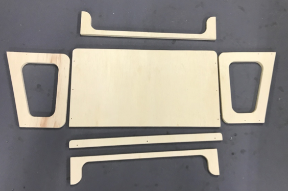
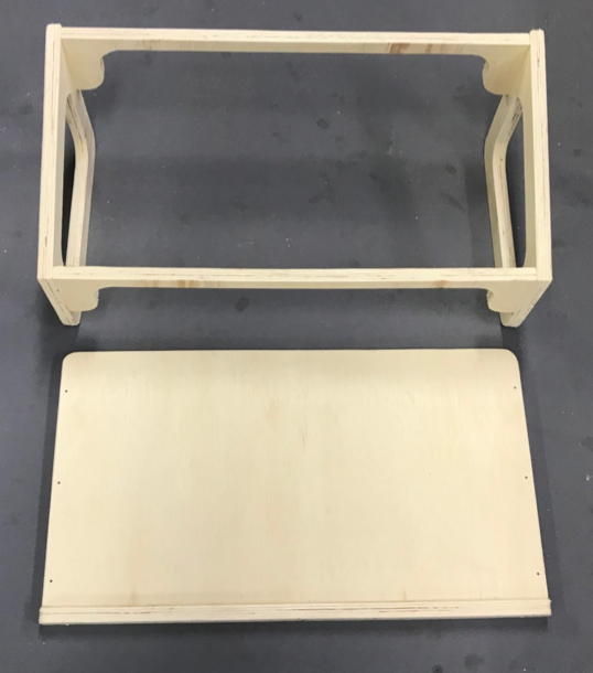
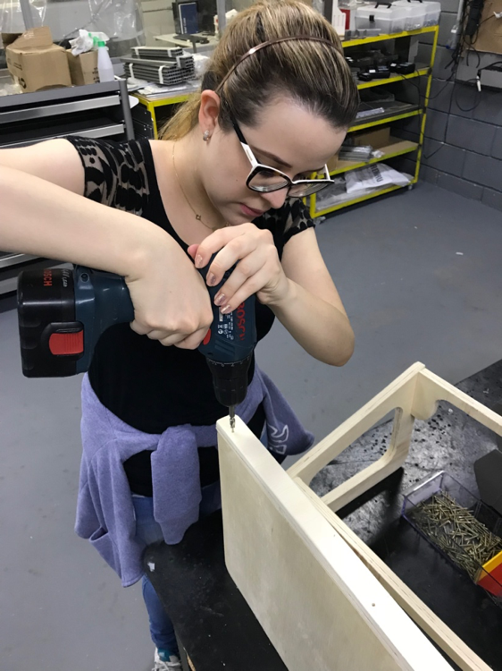
Assembly Of Table
After finished cutting the table, I lifted the pieces and I screwed the
table together using a drill and screws. You can watch a video link of
me drilling the screws into the table:
https://youtu.be/7YBO3SXviK8