ASSIGNMENTS
3D Scanning and Printing
The assignments for this week were:
- Test the design rules for your printer(s).
- Design and 3D print an object (small, few cm) that could not be made subtractive.
- 3D scan an object (and optionally print it) (extra credit: make your own scanner).
Test The Design Rules
I printed a
model available on this website, to learn the design rules of 3d
printing. The reason for this test is to fully understand the rules of
3d printing and how the machine functions.
Note that I
couldn’t find the link on Thigiverse for this model, I forgot to save
the link when I download it, for this reason I printed a new one, you
can see down the page.
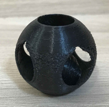
The model that
I chose wasn’t printed exactly how it was in the file, as you can see,
the circle is not perfectly round. One of the reasons it could have
turned out this way is because the file image was to be printed large
scale but I needed to resize the image on a smaller scale so the 3D
printer could print faster. Other reasons could be that I chose a layer
height(mm) and layer thickness (mm) to thin and the low-quality setting
I chose on the Cura software which caused the printer to not properly
print the image. The last reason could be because I didn’t chose the
setting in the Cura softwear called support structure. This setting
allows the machine to build a support structure for an image/object
that is too thin to print on its own and then be removed from the
structure once printed. The structure in my opinion was too thin to
support itself.
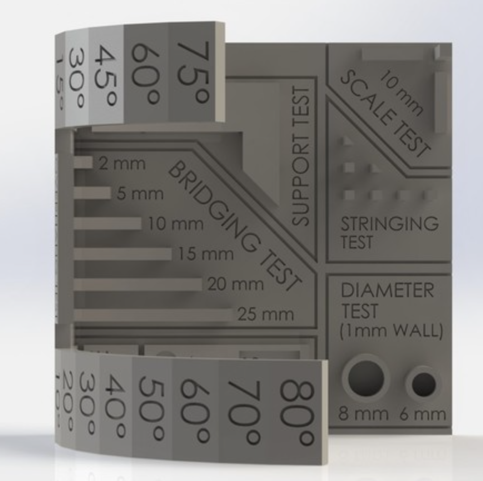
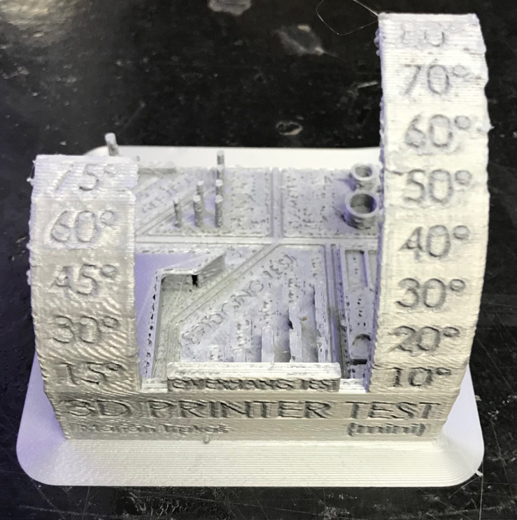
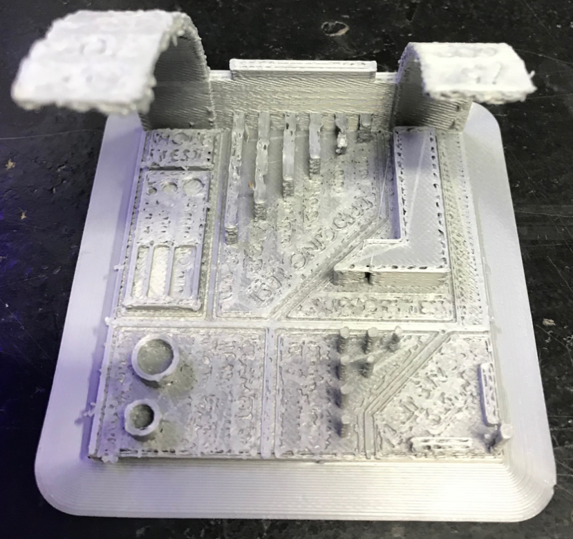
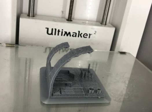
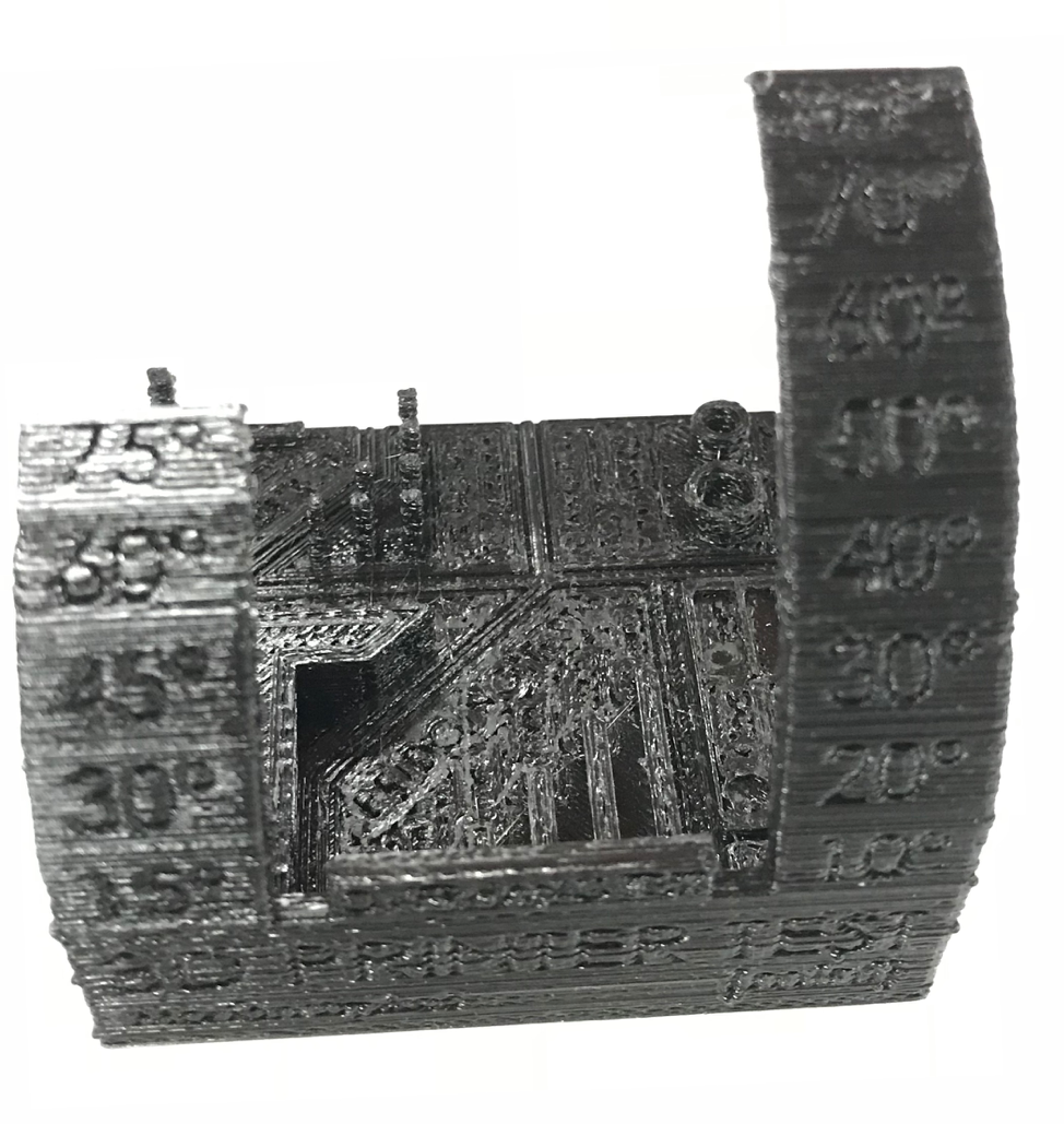
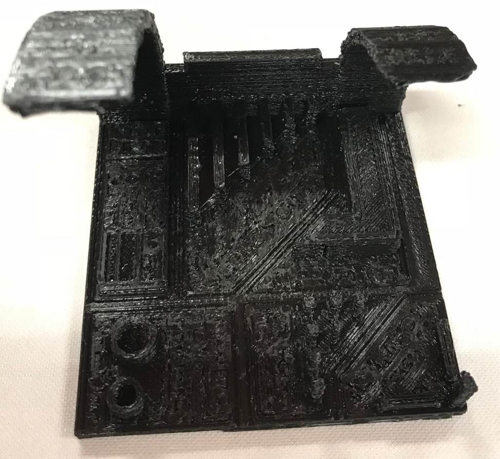
Paulo ran a different test on another printer as you can see in the image below:
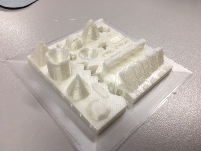
His model tested various printing parameters such as: angles, fine-tipped structures and a bridge without support structure.
Learn more about this by clicking on the link.
Second test.
I also run a second test. To run this test, I download the file from thingiverse.com, the file is: https://www.thingiverse.com/thing:2806295/files
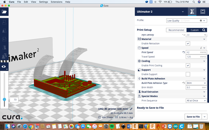
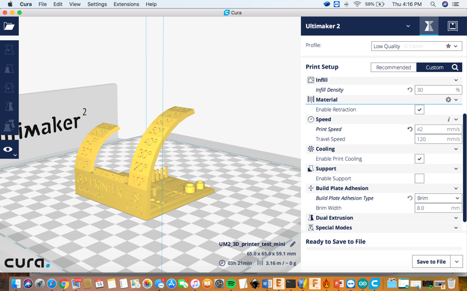
Then I opened the (.stl) file in the Cura software 2.4.0, as you can see in the image below.
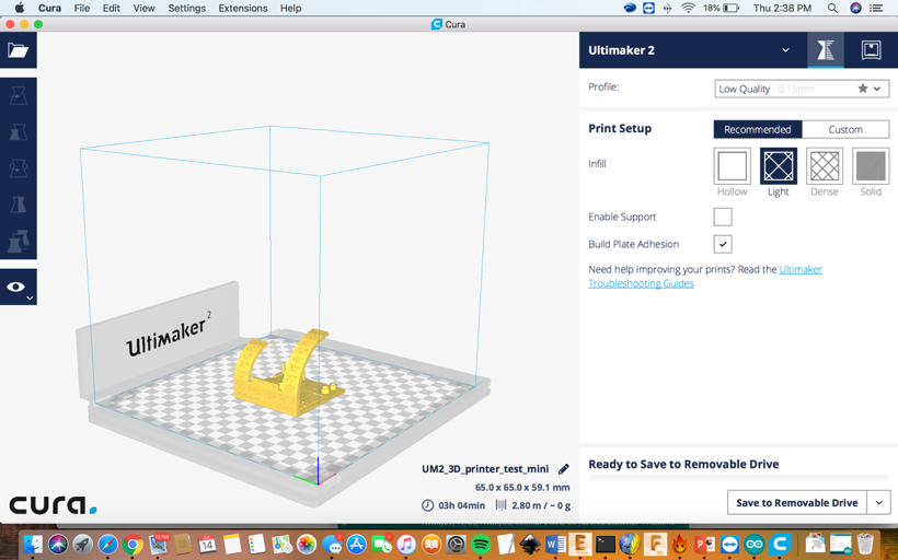
After that, I opened the tool bar on the right side to change some parameters.
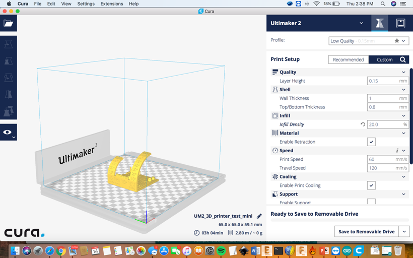
I changed the wall thickness 1mm to 1.2mm.
We can also define the thickness of the shell of our piece, which can
make it much more resistant to later forces.To define the best shell
size we must take into account the diameter of the extruder nozzle, in
FabLAB's Ultimaker 2 we use 0.4mm, so the shell size must be a multiple
of that number, for example:
• 0.4mm - 1 shell
• 0.8mm - 2 shells
• 1.2mm - 3 shells
• 1.6mm - 4 shells
• 2.0mm - 5 shells
• 4.0mm - 10 shells
• 6.0mm - 15 shells
The top and bottom thickness
In this variable we define the thickness that will be 100% solid from the top and base
The gurus at Fab Lab recommend using a multiple number of the Layer
Height variabl. For example, using the standard height we use (0.168
mm), if we want our top / base with 5 solid layers we use 0.84 mm (we
can also use 1mm for 6 layers and 1.17mm for 7 layers), so we have a
great resistance in our piece.
After that I changed the print speedy for 42mm/s.
If you want more detail, a lower speed is always recommended (between
25 and 35 mm/s), but we usually use the standard speed of 41.7 mm/s.
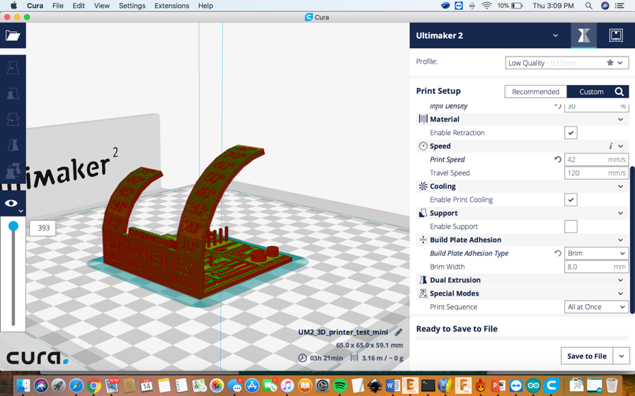
I checked the box to
enable print “Cooling” because, when you are using ABS you need to cool
off the material. Although, If you are using PLA, you uncheck that.
The support
In this case I enable the support because, the main goal in this
assignment is to test the 3D print with angles and different formats.
Build Plate Adhesion
We have 4 options (Brim, skirt, raft, none). I used the brim which is:
The Brim is like a skirt in 3d printing and it increases the area of
contact with the table This allows the model to be more stable in the
printing process. As the piece slopes directly onto the table, the base
will have a matching finish. At FabLAB Facens, the printing table is
made of glass so, we will have a smooth and shiny base.
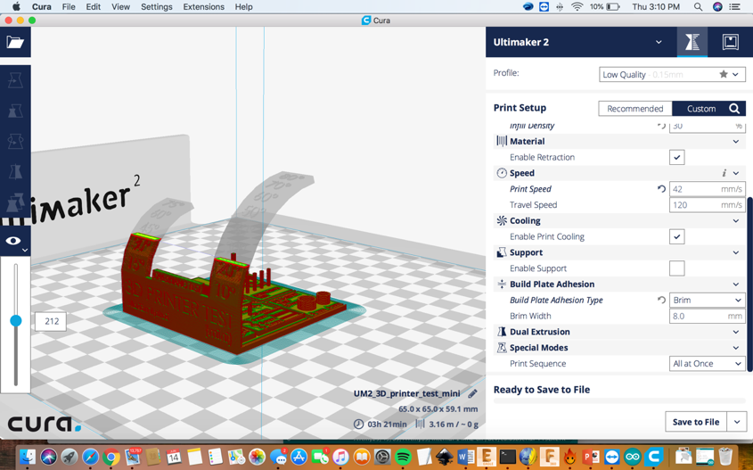
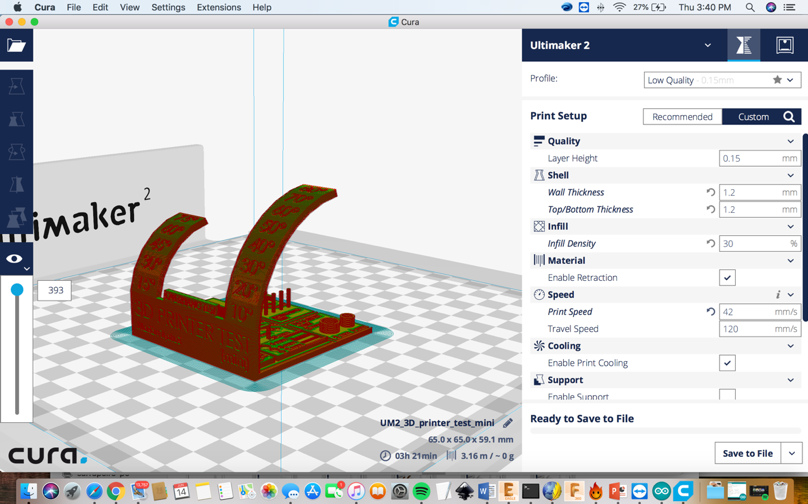
After, I simulate the model in the view mode, as you can see in the next two images below:
Then, the parameters are all set up and its time to print.
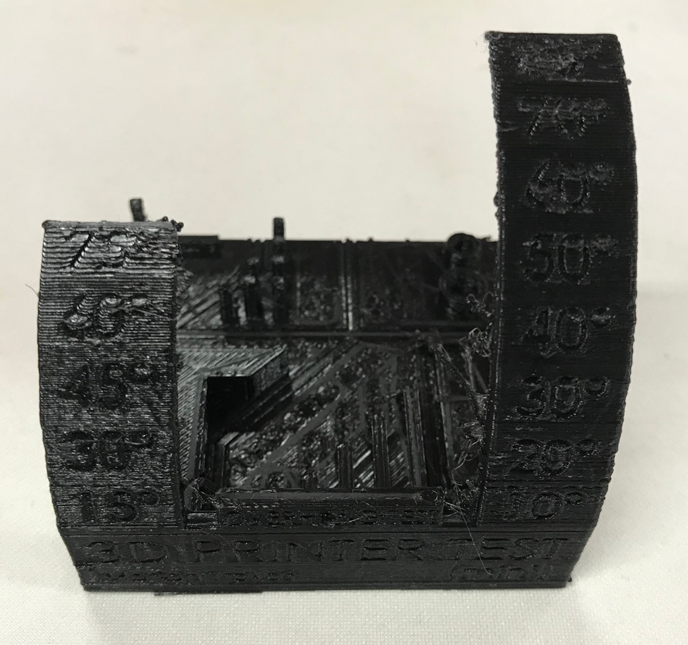
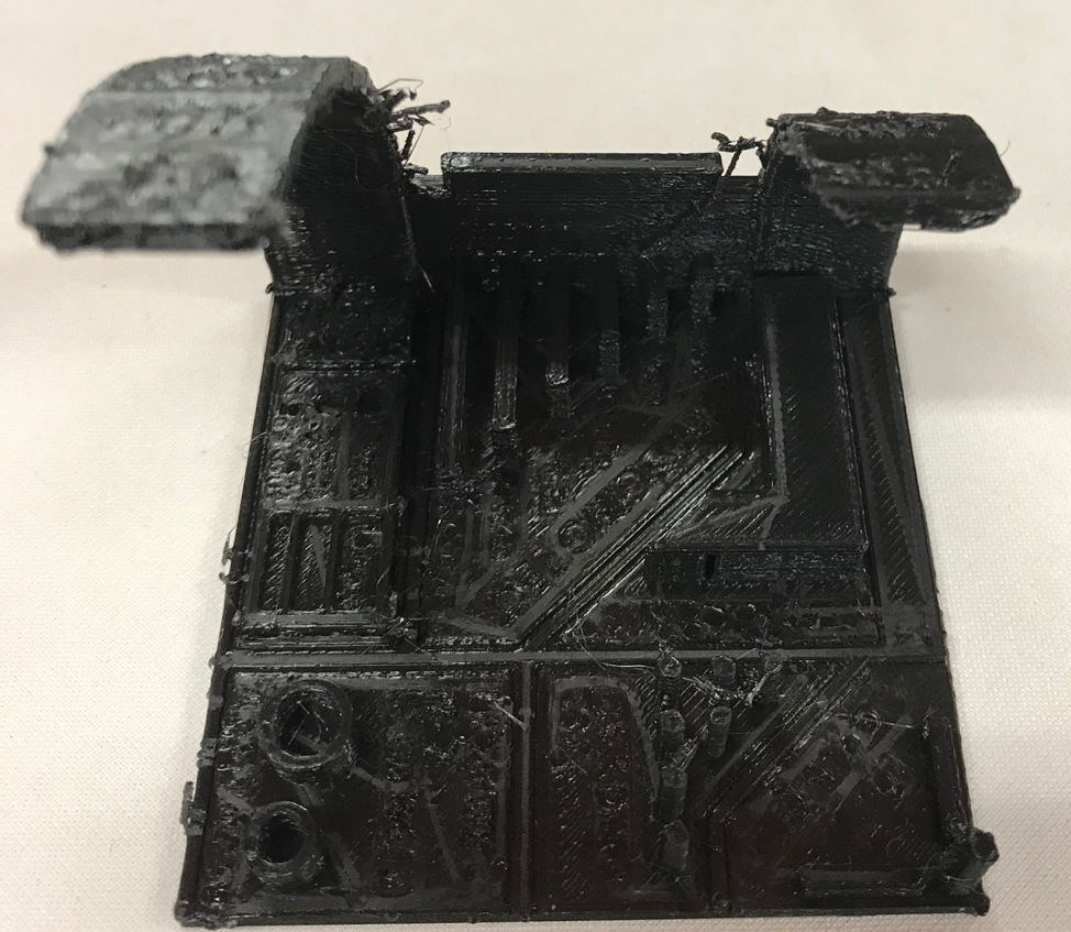
Final thoughts
1) Ghosting Effect: causing distortions on the wall
when needs to make fast movements, because the inertia of the hot end
is moving to fast.
2) The printer is capable of printing at 80 degrees
angle, but the quality underneath is not good at this angle. At 40
degrees is the maximum for the best quality without using support.
3) The bridging test was flawless.
4) Overall there is some problem with the temperature and extrusion.
Below you can see the pictures for the Cura 15.04.6:
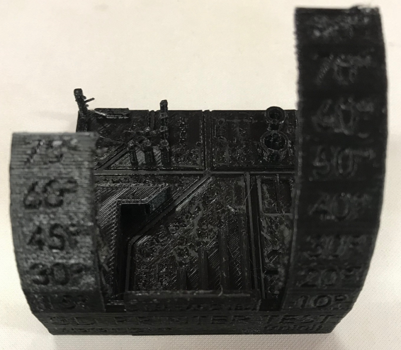
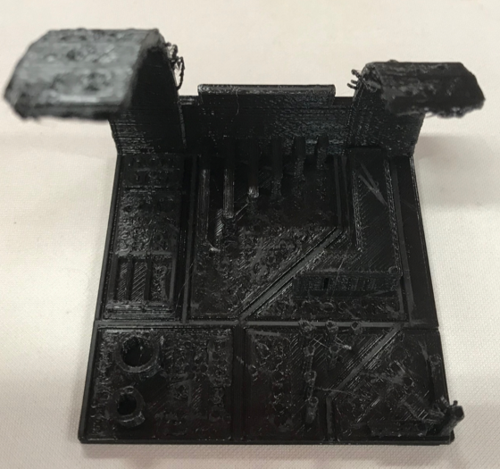
Below you can see the pictures for the Cura 3.3.1:
Comparing the 3 models using the Cura (versions: 15.04.6, 2.4.0 and 3.3.1) we can see a lot of differences:
-The first noticeable is the ghosting effect being heavier on the older version.
-But, still, have less stringing than the more recent one.
-About the support angles test. The first thing we can notice is the
corner issue at the older version beginning at approximately 20
degrees. But the underside of this test has a good appearance until 55
degrees approximately, on the top side there are very few issues in the
test, we can see a bit of over extrusion in some points probably caused
by the software. However looking at the test using the new Cura the
issues on the top of the test has become more noticeable at higher
degrees, the underside of it is another history, there are no corner
issues, and also 55 degrees maximum angle (this is the limit with the
Ultimaker 2), but in all prints using the Cura versions it was able to
print all the angles.
-In the diameter test, we could analyze in all
pieces we had a thicker wall that is supposed, in the 15.04.6
version, the cylinder with 6mm was smaller and in the 8mm was bigger.
However, in the version 3.3.1 was perfectly precise.
-Talking about the bridging tests, we can see in the older version it
is perfectly flat, compared with the recent version there is some
warping, a little bending on the underside of the bridge.
Below you can see the pictures for the Simplify:
-The first detail we can see is over extrusion, it was printing with a bit o too much plastic, causing some deforming.
-In size of the cylinders, it was not perfect as the Cura 3.3.1 but was not so far of as the Cura 15.04.6.
-The pillars were strong but very deformed.
-There was almost zero stringing.
-In the bridging test, it was almost perfect with less warping than the new Cura.
- When we start to talk about the overhang test was flawless, getting
up to 70 degrees without deforming, and we can see so less deforming at
75 and 80 degrees with no corner issues, it is perfect.
Advantages & Disadvantages:
- To build objects that have internal
structures. To use that in other fabrication process (milling for
example) it would be necessary to make two or more different parts and
then assemble it.
- The size of construction is a limitation. Also the 3d printing
process limits the types of materials you can use. PLA and ABS aren't
to friendly to use with water.
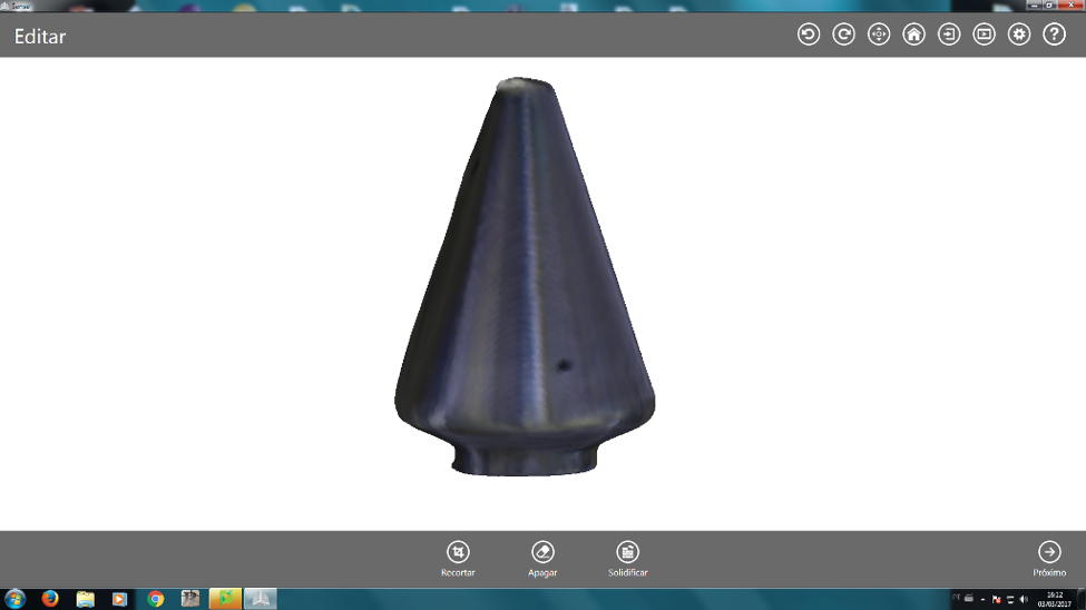
Design and print a 3D model
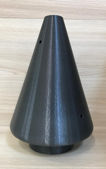
For the 3D printed object, I wanted to make a
conical essential oil Extractor which I will use in my final
project.The first step was to make the 3D model in SolidWorks, I also
parametrized all the measurements of the conical essential oil
Extractor. I parametrized the y axis: . .
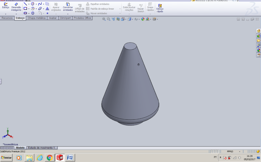
(3D model in an isometric view)
Parametrization:
is using equations and global variables to apply dimensions to your
sketches. The reason for this is to make it easier for the solid works
user to apply larger or smaller dimensions to any of the dimension
measurements using the shortcut of a preset parametrization equation.
For example, all you have to do is change one of the dimension
measurements and it will automatically change them all. The
equation for parametrization in solid works is =Function.
I didn’t know how to parametrized a 3D in
SolidWorks, so I watched some Youtube videos before I started, here is
the one that I could understand the best on how to do it:https://youtu.be/ltRL0qXgo2A
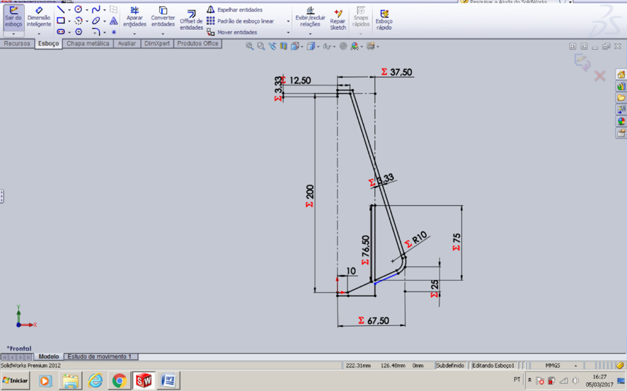
Also below is a picture of my support leg parametrized. It’s not so hard to do it.
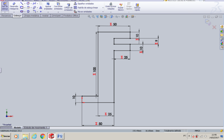
Here are the steps of how to design the image using a parametric measure including my measurements:
1) Insert your sketch
2) Click one of the lines of your sketch
and then you click smart dimension tool at the top left of the
window.
3) A small window will appear and Insert the line dimension you prefer in (mm)
4) Create a global variable by clicking the tool next to the red x button
5) Type an = then type in your name for
the variable then accept the variable by clicking on the 
symbol
6) Click on another sketch line and
repeat steps except for this time insert an equation as you can see
in the image bellow and click accept.
7) Continue these steps where you see fit to parametrize the dimensions of your sketch.
If you have any doubts how to use SolidWorks I would like to recommend this video fromYoutube:
https://youtu.be/YlJeaIwrMro?list=PLCE6728E47A919344.
It helped reminde me how to make a 3D model using Solidworks.
Snce I already knew how to use this software since 2015, when I
designed a chemical car to participate in a competition in my
university.
The next step was to convert the 3D model to .stl. So the  (3D
printer) could print my model. The process to do this is, you first
need to click the File tab at the top and then click save as. The save
as window will open up and then you have to click the file format tab
and select the format .stl . Once you chose the format hit save. (3D
printer) could print my model. The process to do this is, you first
need to click the File tab at the top and then click save as. The save
as window will open up and then you have to click the file format tab
and select the format .stl . Once you chose the format hit save.
After that I opened my model in the Cura software, which is the software that the uses.
When I opened up the cura software a basic setting toolbar was on the
left and a theoretical model of my extractor and the inside of the 3D
printer was on the right of the toolbar. A few other things I noticed
were the tool buttons located at the top right, top left and bottom
left.
I played around with the tools and these are the ones I found most useful:
Rotate option- Rotates on 3 axis which is helpful because it allows you to find the best position to print your model.
Scale- Sometimes the program you use to sketch and save the image is
not in mm and can confuse the cura software by converting the image
automatically to mm causing the object to come out very small.
SD- To Save your object on a SD card because the 3D printer only reads SD cards. (Always remember to insert SD card)
Layer Mode- Allows you pull away the layers and see the infill. This also allows you to see where your structure is hallow.
The Settings that I found important are:
Quality:
Layer height (mm)- The larger your layer height is the longer the
print time takes. If you make your layer heights to small you may end
up with gaps in your model. I chose 0.2 mm because it is the
recommended layer height for both printing time and structure support
Shell thickness(mm)- Is the thickness of the outer shell of your model. I chose 1.2 mm.
Fill:
Bottom/top thickness(mm) – This controls the thickness of the bottom
and top layers, the amount of solid layers put down is calculated by
the layer thickness and this value. I chose a thickness of 1mm
Fill Density(%)- Controls how strong the part becomes. Usually set at
20%. For a solid part density is set to 100% and if part is empty it is
set to 0%. I chose 10% for my Extractor because I did not want it to be
fully hallow.
Speed and Temperature:
Print Speed (mm/s)- Affects the quality of your print. The slower the
speed the higher the quality is and the faster the quality gradually
gets worse. I chose a print speed of 30 mm/s.
Support:
Support type- There are 3 different support settings. None creates no
support, touching build plate only creates a support where the support
structure will touch the build platform and the final one is everywhere
which creates support from top to bottom. I chose none.
Platform adhesion type- This allows the filament to flow through the
nozzle before it starts printing your model. Which allows for a
smoother transition into your first layers. The two options are skirt
and brim. I used the brim option because my model didn’t have a lot of
contact with the bed.
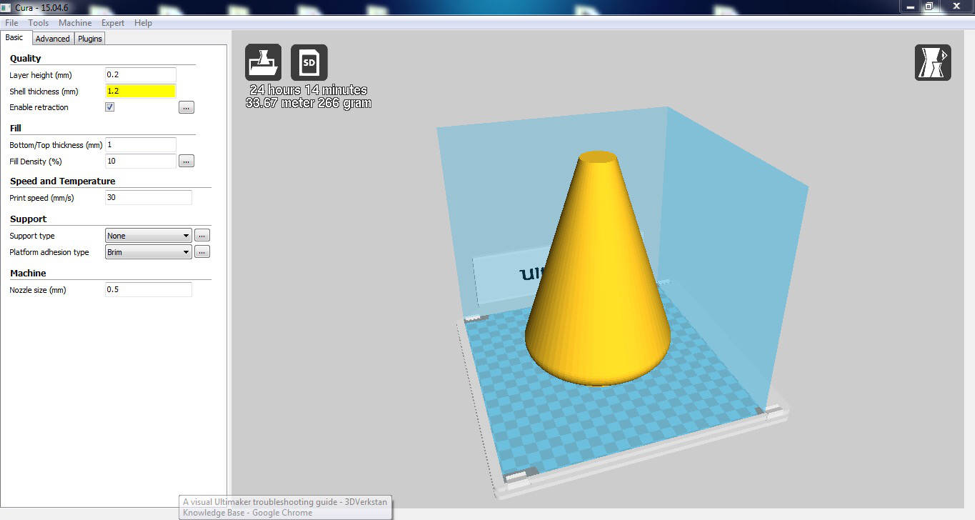
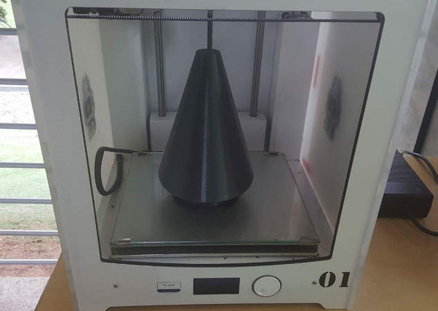
As you can see, it took 24 hours and 14 minutes to print, we left the
machine printing overnight, and was used 33.67 meter and 266 grams of
PLA (polylactic acid).
Here is a helpful link for this process is: https://www.youtube.com/watch?v=6YZD6K7osco
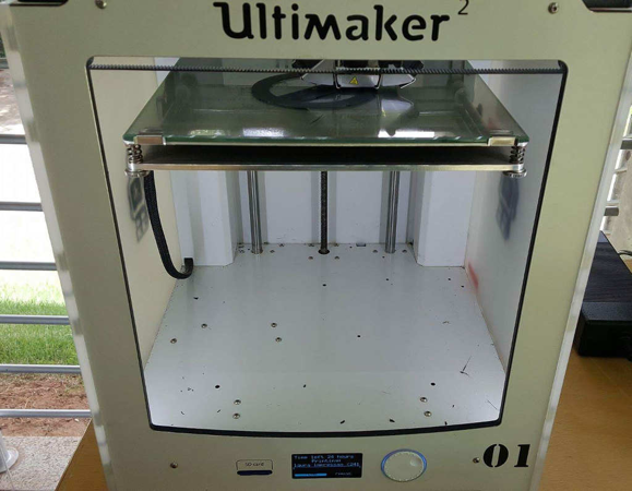
Below is a picture right after the machine started:
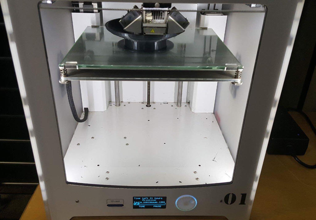
I then took another picture a little later so I could make sure that my
model was printing correctly. It was, so, I left it printing over the
night.
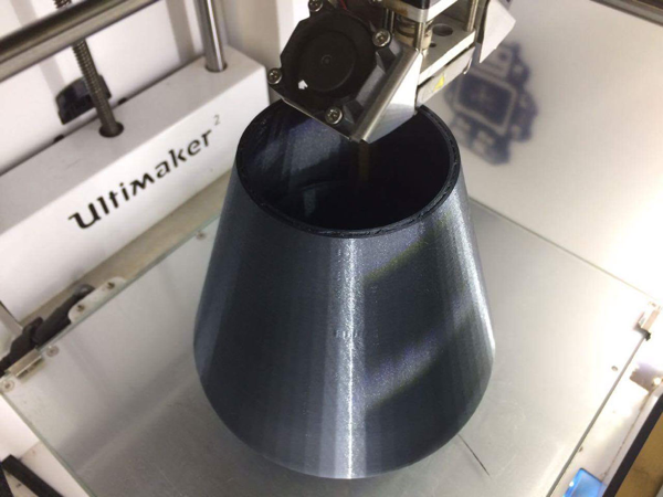
When I arrived at the Fab Lab in the morning, I took another picture.I was very excited to see the extractor was almost done.
Some hours later, the extractor completed printing.I really liked the
results, the extractor was as perfect as I designed it to be.
Calibration of Ultimaker 2
I used these exact steps for my project these are the same steps copied from this link.
https://ultimaker.com/en/resources/146-calibration
Bed Leveling:
After the “Welcome” screen, the Ultimaker 2 will guide you through some
steps for calibrating the build plate. For printing it is very
important that the first layer is nicely squished into the glass plate
and sticks well to it. If the distance between the nozzle and build
plate is too big, your print won’t stick properly to the glass plate.
On the other hand, if the nozzle is too close to the build plate it can
prevent the filament from extruding from the nozzle.
Before the bed leveling can be done, the Ultimaker 2 will first do the
"homing". This means that it will move the print head to the left back
corner and the build plate towards the bottom, in order to set the
origin point. After this, you can follow the next steps for leveling
the build plate.
Note: If you don’t see the configuration wizard, navigate to "Maintenance" > "Advanced" and confirm for a Factory reset.
Setting the height:
The first step is to roughly level the build plate by rotating the
button at the front of your Ultimaker 2 until there is approximately 1
mm distance between the nozzle and build plate. The measurement here is
not critical, just make sure that the nozzle is close to the build
plate without touching it.
Rough Leveling:
Next, a rough adjustment will be done on the front left and right side
by turning the build plate screws. Turning the build plate screws to
the left means that the build plate will get closer to the nozzle.
Again, there should be approximately 1 mm between the nozzle and build
plate.
Fine-tuning:
The last step will be fine-tuning of the build plate with the
calibration card. Place the calibration card in between the nozzle and
build plate on all 3 points and adjust the build plate screws until you
feel slight friction when moving the card.
Note: Don’t push on the build plate while fine-tuning with the calibration card; this will lead to inaccuracies.
Ultimaker 2 Specifications:
Build Volume: 22.3 cm × 22.3 cm × 20.5 cm
Layer resolution: up to 20 microns
Print Speed: 30 mm - 300 mm/s
Travel speed: 30 mm - 350 mm/s
Filament diameter: 2.85 mm recommended
Nozzle diameter: 0.4 mm swappable
Operating nozzle temperature: 180°C - 260°C
Operating heated bed temperature: 50°C – 100°C
Frame Dimensions: 35.7 cm × 34.2 cm × 38.8 cm
Printer technology: Fused Filament Fabrication (FFF)
Software: Cura
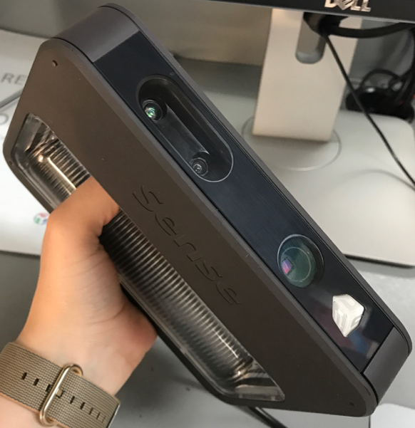
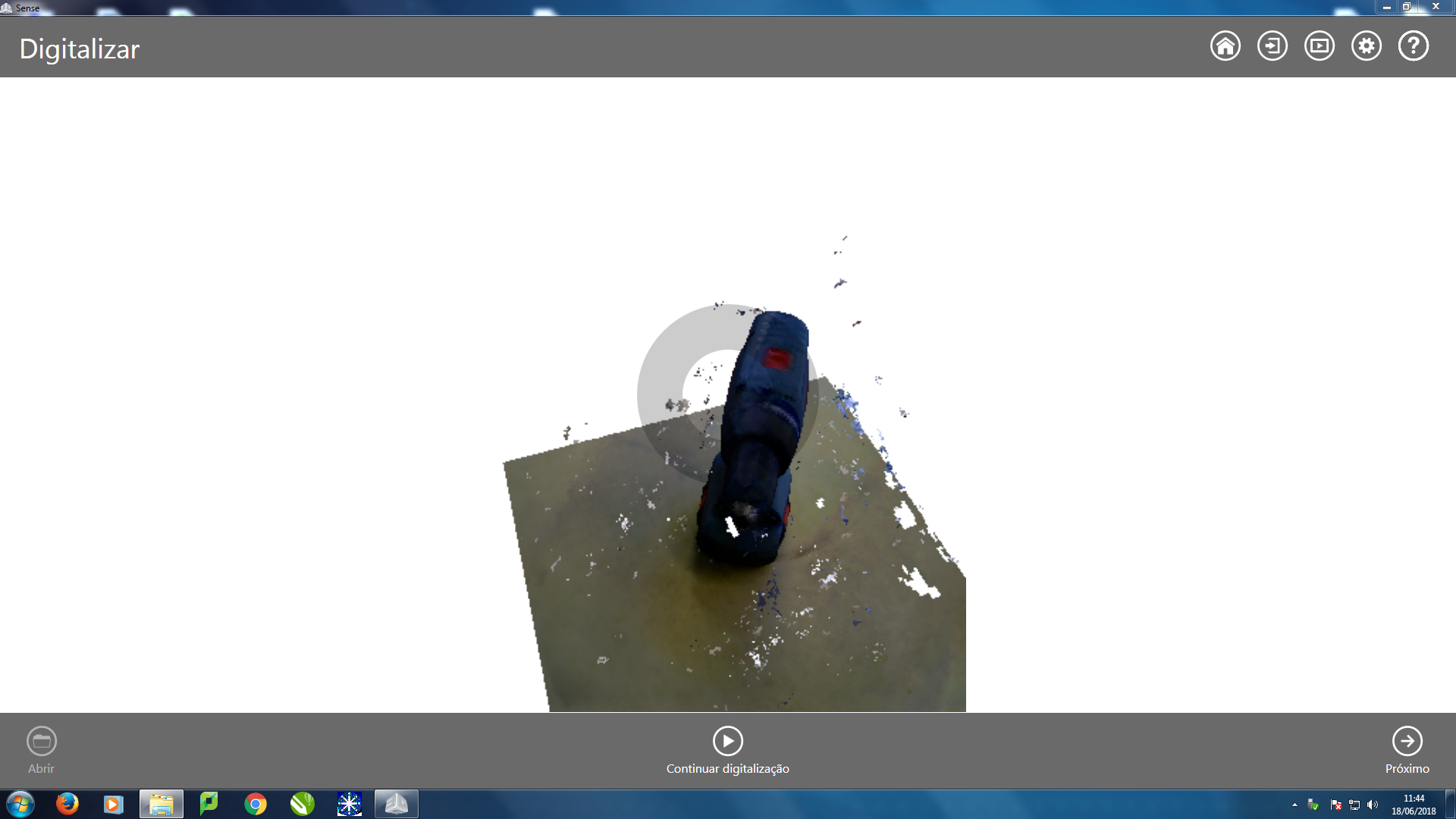
3D Scanning
One of the
assignments for this week was to make a scan of what you printed using
the 3D printer. I used the Sense scanner and software name is Scense 3D
Scanner. to scan my extractor. The machine and software has limitations
on what it can scan. Its limitations include scanning details such as
rolls and internal parts.
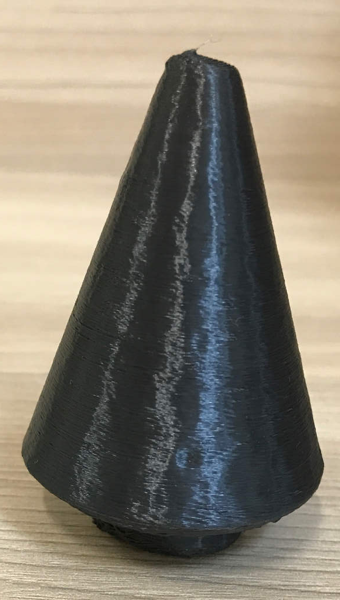
I
didn’t like the result because it was a little
deformed but, I still decided to print it on a small scale because
there wasn’t a use for it other than learning the process. One possible
reason that the scan came out a little deformed was because the
environment was very bright which may have interfered with the
scan. Also, I believe the deformation happened because it scanned the
object lying down, since when leaving the object standing the software
was not recognizing the format and was not being able to scan.
I did a second 3D scanning to show the step by step.
Note the program is in Portuguese language.
1) First you press the start button.
2) After that you press the next button.
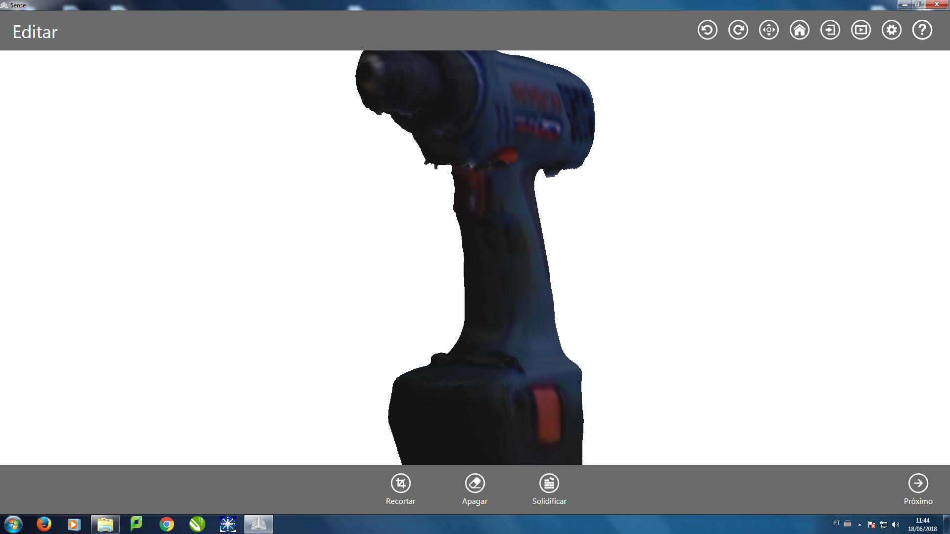
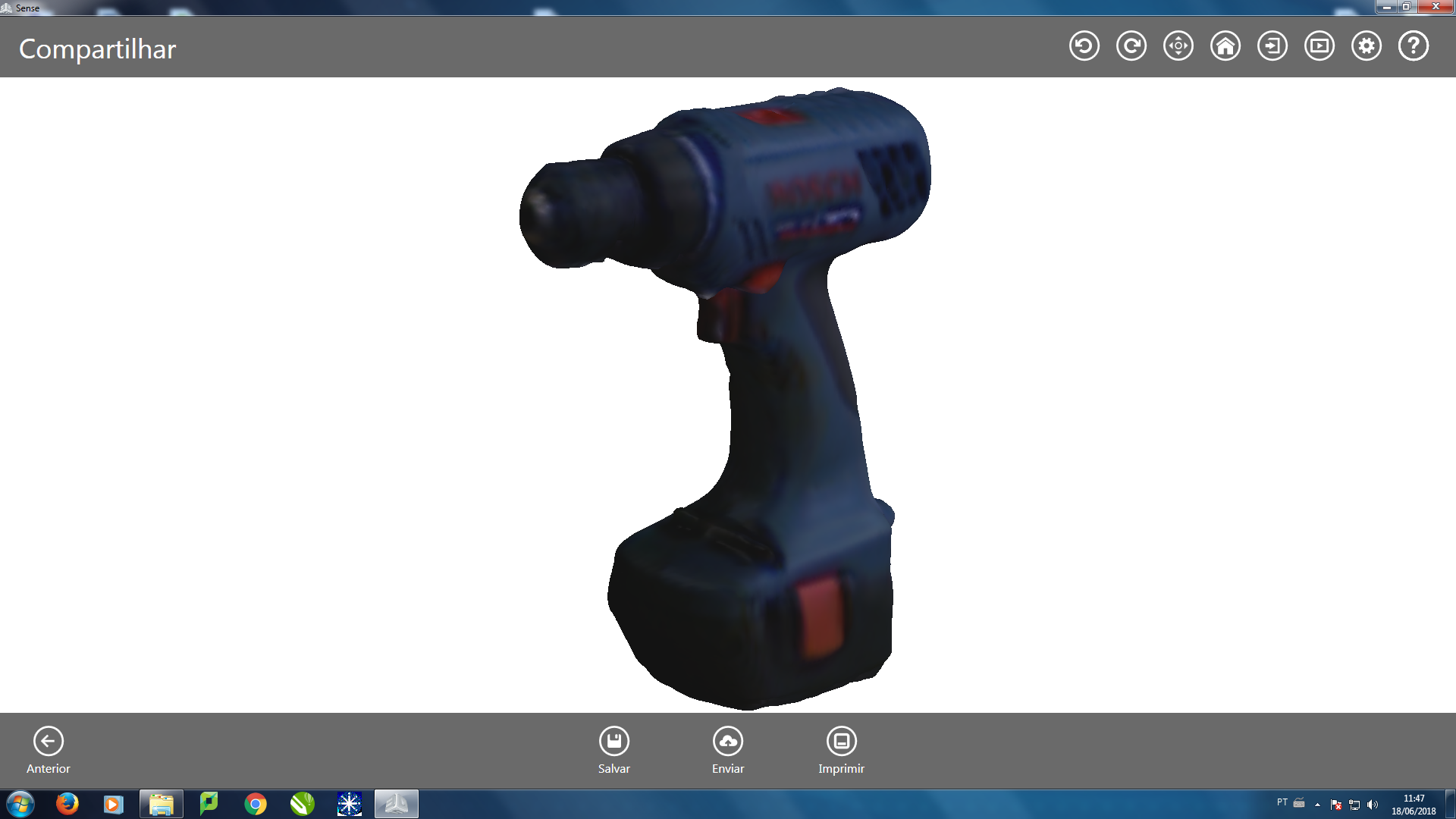
3) After that you use the tool called "solidify".
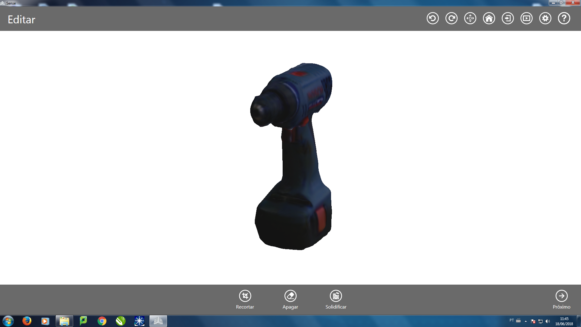
4) Now you have the solidified designer.
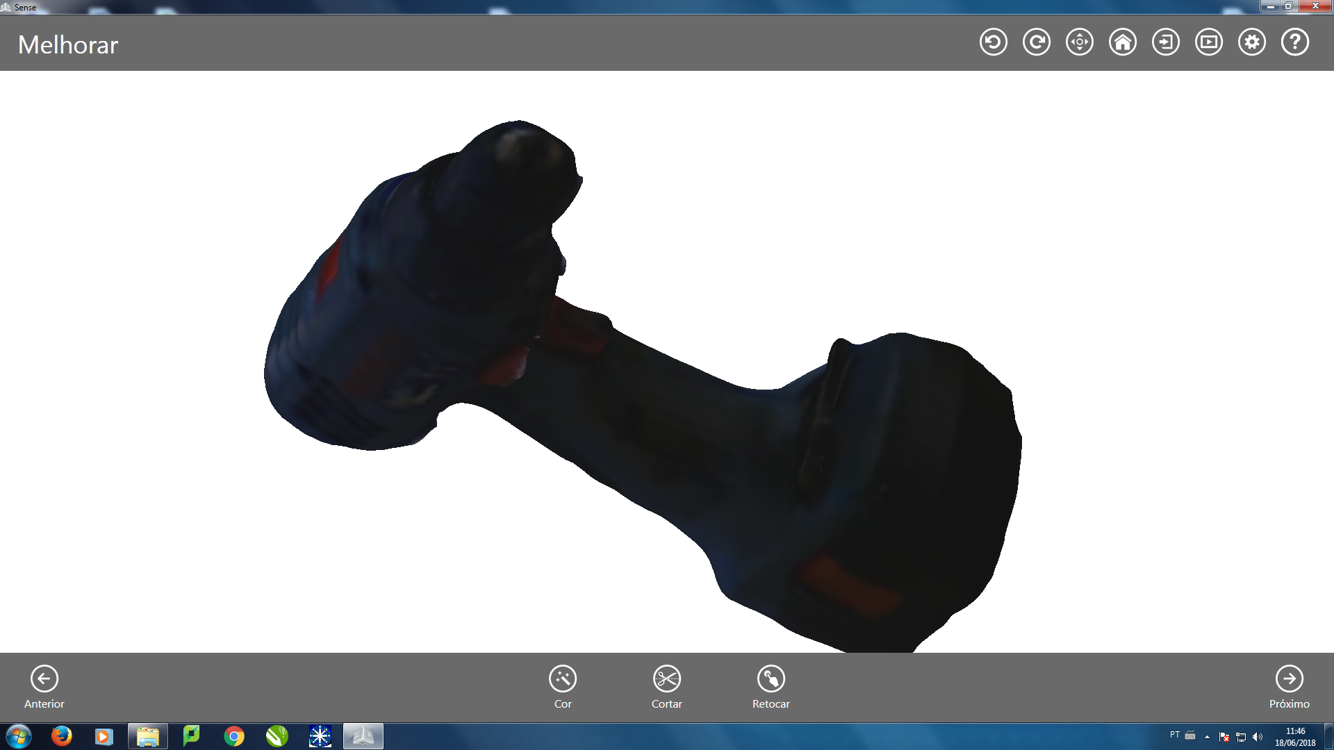
5) After that you are ready to save the file as (.stl).
|