After
reading the Safety Data Sheets (SDS) on these chemicals I realized that
most of the chemicals we used in this assignment are hazardous if
breathed in and are dangerous to the skin so, you should use protective
gear when using these chemicals. Being a chemical engineer and always
taking into account the safety practices when using chemicals and
machines, I find that these SDS are highly important to read before
using the chemicals. Safety was the number one thing thought throughout
my schooling in regards to chemicals. Also note that SDS can be general
to extremely thorough.
At first I created
a negative mold model using Solid Works. This was wrong because, you
need to design a positive mold. I decided to make a 2-part model with
thick walls in 3D using SolidWorks for my mold because, a 2-part mold
is needed to make two models. One for each side of the mold. First I
placed the vent on an axis of symmetry so that I didn’t have to worry
about lining up the vents when I make the molds. I made a model with
each side separately and I include registration marks as well as a
vent. I chose to make big size models with thick walls to make my life
easier when I pour in the silicone mixture. I made two separate holes,
one for to use as vent and the other to pour the mixture in.
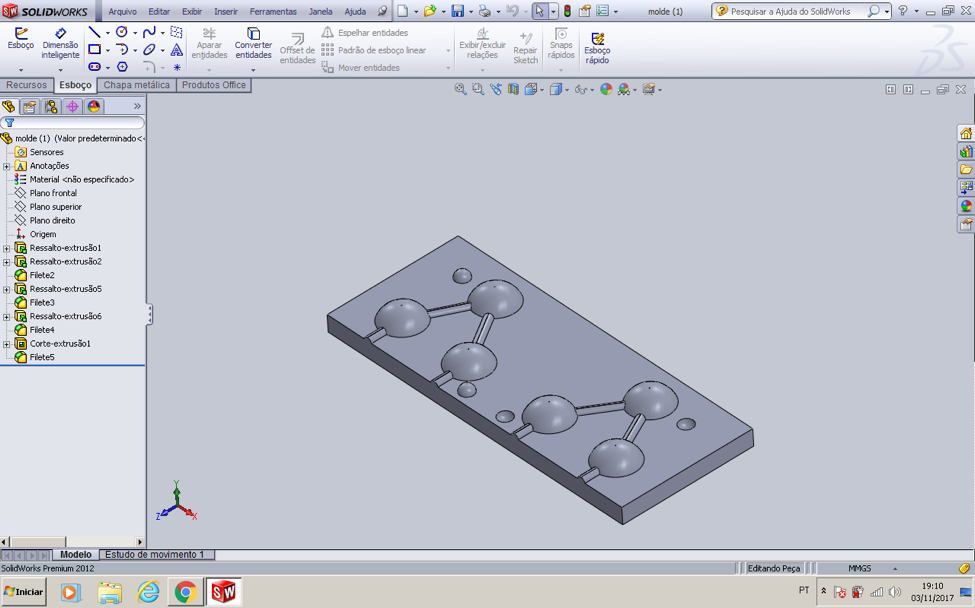
I designed a water molecule mold as you can see in the image below:
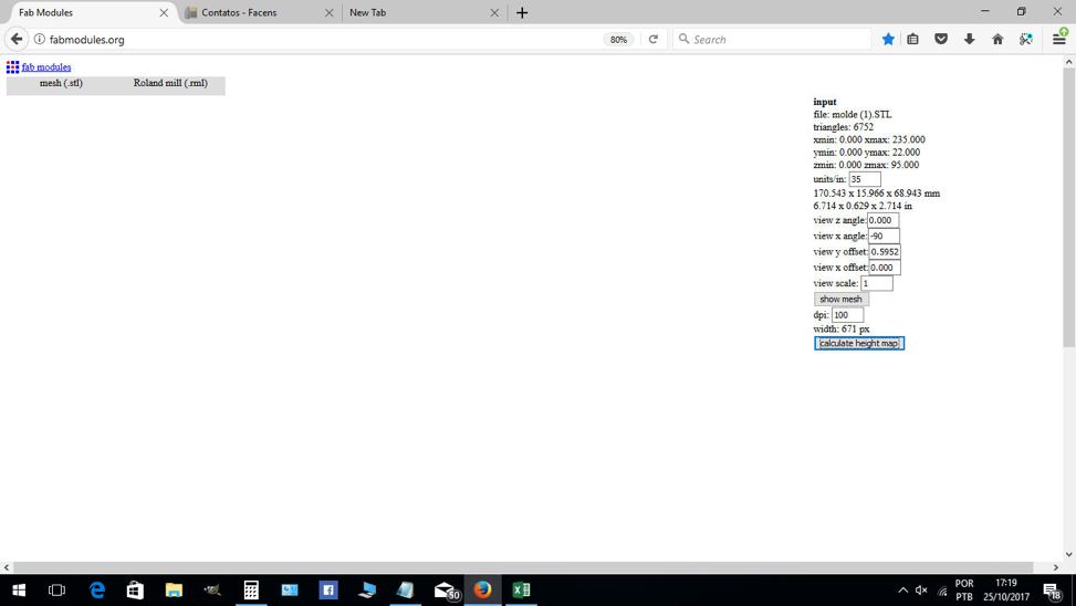
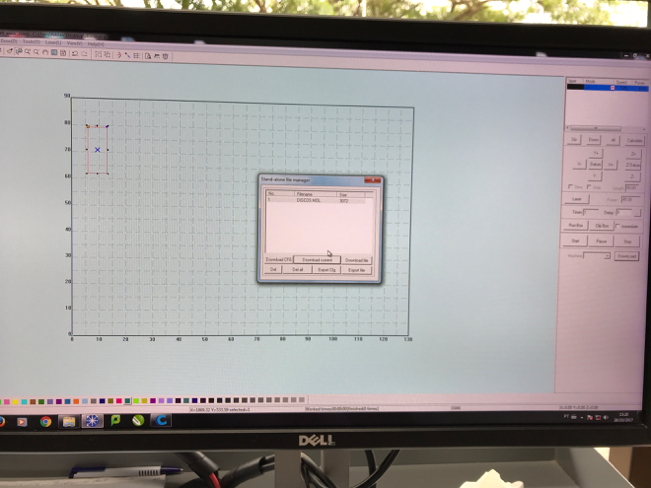
After I finished designing my mold I initially saved the file in .stl
format. This was a mistake and I had only just realized the mistake
when I opened the Modela and an error message saying that the file was
not a binary .stl. So, I saved the file as a binary .stl.
Note:
Make sure the
file extension is lowercase (.stl) not uppercase (.STL) because, the
Fab Modules doesn’t recognize an uppercase
extension.
Place the vent at the top of the part! You don't want to vent out of
the bottom of the part because then material will just pour out!
Milling The Wax On The Modella:
The next step is to mill the wax on the Modella but, first you have to fallow these steps:
1. Open Fab Modules Select PNG to Roland Modela
2. Click "load STL" to load your image. The STL will load in the window.
3. Select "rough cut" from the
drop-down menu. The interface will populate with the default settings
for a rough cut
using a 1/8" bit.
If you are not
using a 1/8" bit change the diameter.The bit size must be in
millimeters. The other settings should be fine.
4. You need to change the 3D
settings to work for your model. Click the 3D settings button and a new
menu will pop up .png 3d default.
5. The top height setting tells the machine where to start milling the top of your file.
6. The top height value must be 0 or negative. A positive value will result in an error.
7. The bottom height setting is
how tall / deep you want your model to be. This must also be a negative
number or you will get an error.
8. You can see from the toolpath
generated that this bit is a little too big to get all the detail in
this model. Use a smaller bit diameter and
generate
the toolpath again. You can do this to preview the path. After you can
see the detail, you can put the appropriate bit in the
Modela.
9. Zero out your Z axis to the top
of the wax. Stop when a few shavings of wax come up. Click "make rml"
and then send it to the
machine. After the job completes, create the finishing pass - select
"finishing pass" from the dropdown.
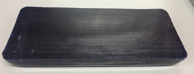
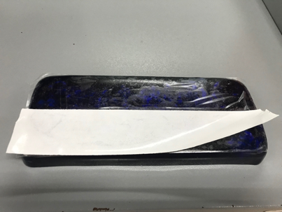
After generating the code, I placed the paraffin wax on the table and
put two-sided tape to give the wax better stability. Also, I used hot
glue as you can see in the images below.
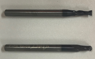
Since my model is curvy I used a ballnose bit with a diameter of 3mm
and for the flat parts I used the endmill bit with a diameter of 4mm.
See in the image below:
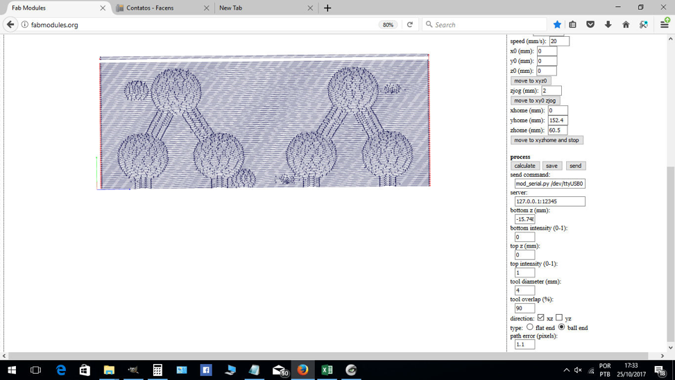
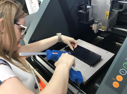
I measured the tool and the spacing between the parts and detailed
where I wanted the bit to pass through. I made sure that the bit was
small enough to cut out the detail in my model. I previewed the
toolpath in the Fab Modules before I cut it. The blue lines are the
cutting parts and red "movements in the air". I also paid attention to
the depth of my model because smaller diameter bits have shorter
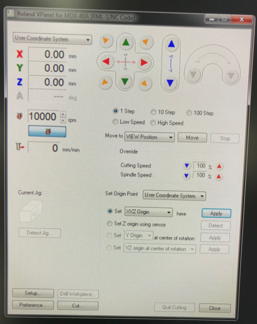
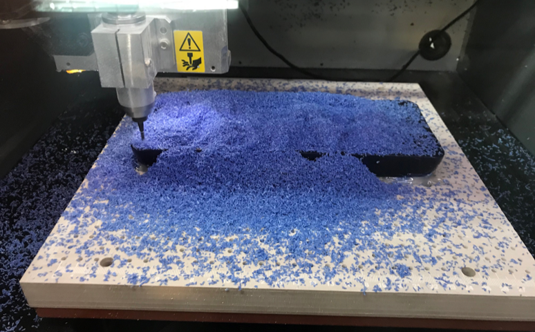
cutting depths.After I placed the first tool in the machine and the
paraffin wax on the machine, I needed to set up the x,y,z axis by using
the V-panel (machine software). I stopped when a few shavings of wax
came up. See image below:
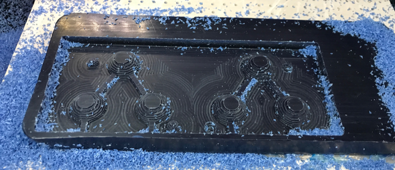
Zero out your Z axis to the top of the wax. I calculated and ran my
rough cut. After a few minutes and a few hours later, I took the
pictures below.
(Few Minutes
Later)
(Few Hours Later)
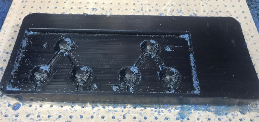
Then I put the ballnose bit with a diameter of 3mm in the machine to
give a better appearance to the model. I used a round type and I set up
the Z axis again. This process took around another 30 minutes or so to
complete.
You can watch a video:
https://youtu.be/INc-bZ6dkVg
Making A Mold From The Wax:
The next step is to create a mold using the wax. Before I started this
process, I used the laser cutter to cut a 9mm wood piece “to close” the
model. In the picture below you can see that I used Studiocut to design
the wood piece.
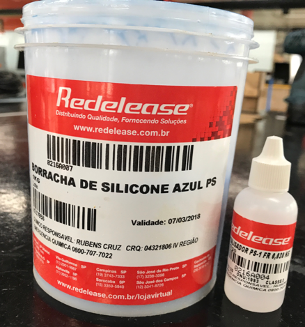
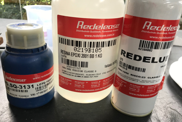
Then I got everything ready before I opened and mixed the chemicals.
The next steps were to measure the volume of chemicals that would be
need to fill my mold. Bellow, is the picture of the silicone and
catalyzer chemicals that will be mixed together to form my mold.
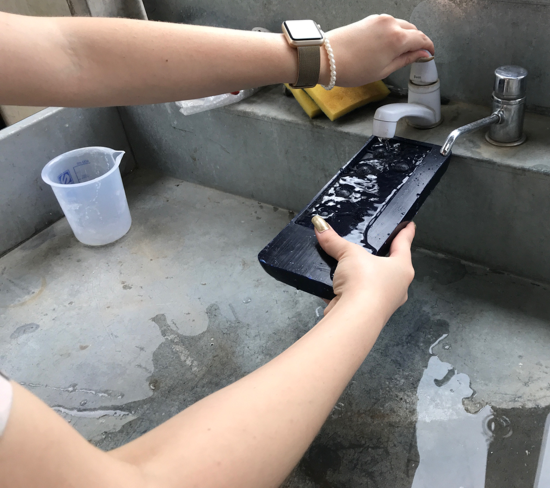
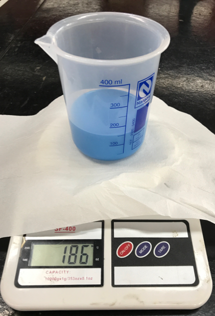
It was now time to measure how much silicone was needed for the mold by
pouring water into the model and then measuring the water volume. The
water valume measured 186 g of water. After I measured the water
volume, I poured the silicone and the catalyzer. Then I mixed the
silicone and catalyzer together in the fallowing proportions 1:1/4 and
weighed it in a beaker to match the amount of water volume previously
measured (see images bellow).
Note: I found
it better to use the exact amount measured for your silicon mixture as
it will make a more accurate mold and there will not be any wasting of
the material.
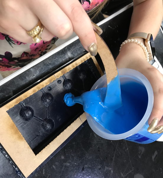
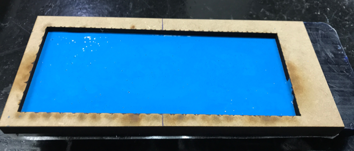
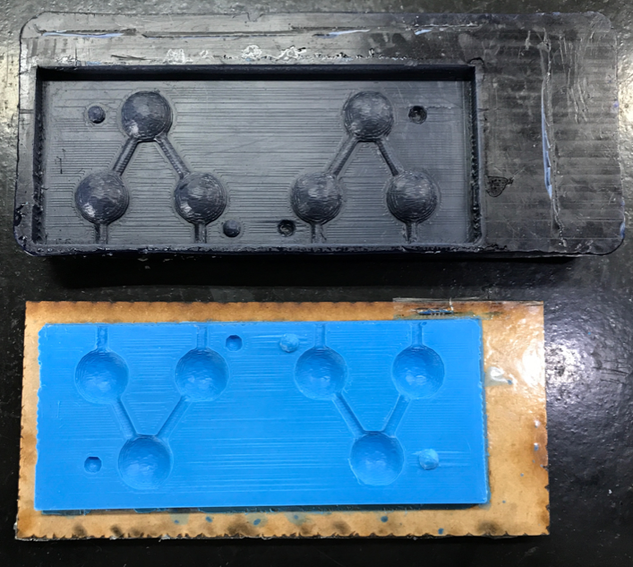
After I mixed the mixture and I poured it into the wax mold. I left it
to dry for 24 hours. In the first and secound pictures below you
can see the wood piece that I cut on the laser cuter during a previous
step. 24 hours later my mold was ready and hardened enough to be taken
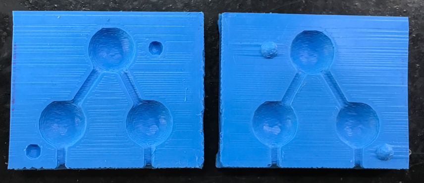
out of the tool. I took the mold out and split the two sides of my mold
cutting them in half with a utility knife. In the third and fourth
pictures below you can see the results.
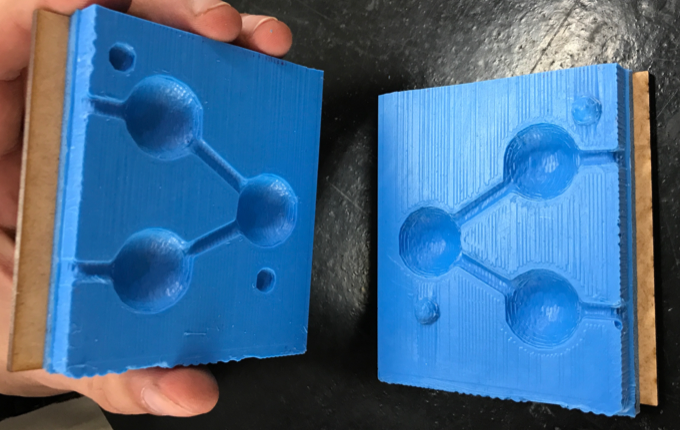
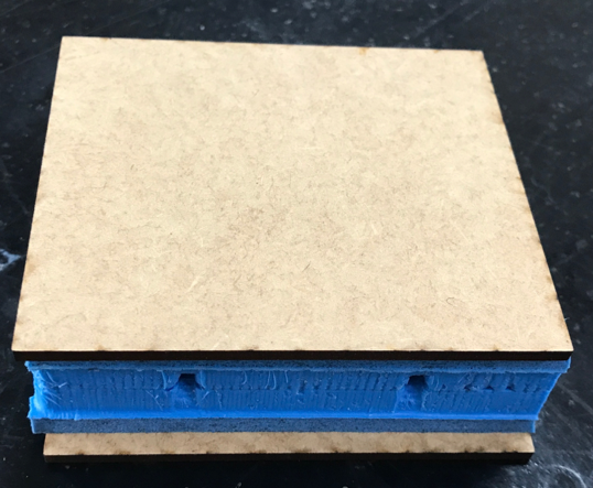
The next step is to tape or glue the scrap wood to the backsides of the two
sides of the molds to add extra stability. Then spray the two sides of
the mold with a releasing agent so the material doesn’t stick to the
mold and place the two molds facing with the vent and pour holes facing
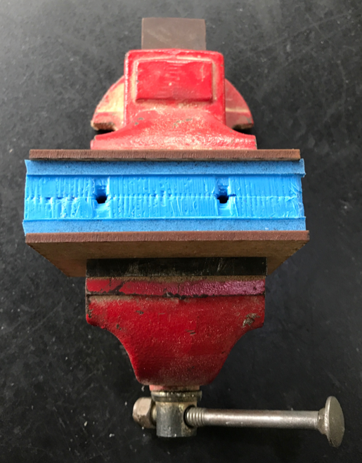
upward. After that, place the mold into the clamp to hold the two sides
together tightly.
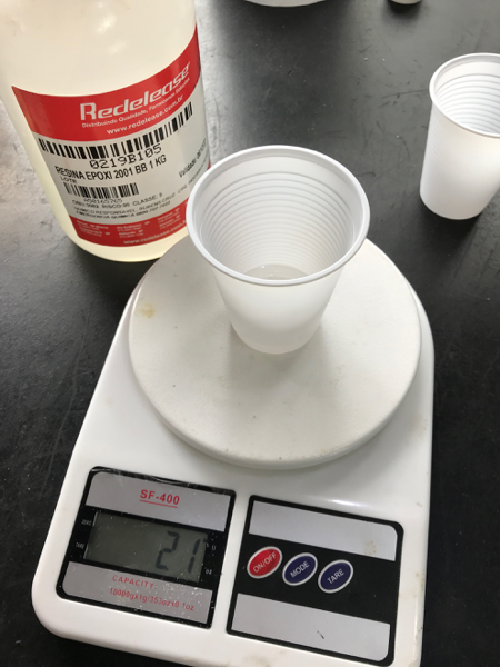
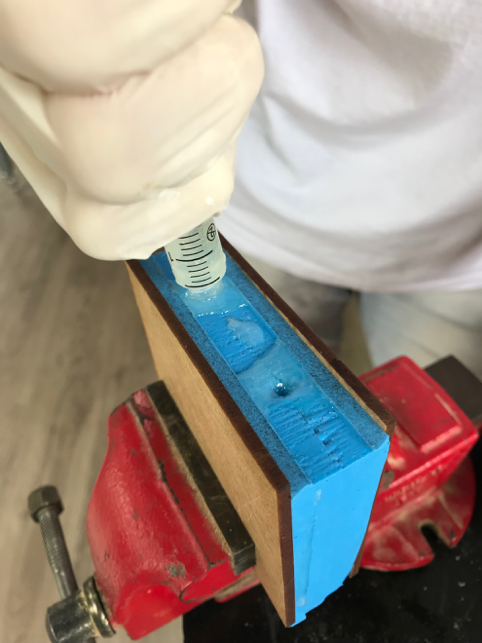
After placing the mold into the clamp it’s time to measure the
chemicals needed to cast the water molecule. To measure how much
chemical mixture was needed I used a siring with water. I first poured
the water slowly into the pouring hole of the mold until a small bubble
came up. I measured how much water was used and then made the same
measurement for the chemicals. I chose to use a clear rubber epoxy and
also use a hardening chemical. Below you can see that 21 grams of epoxy
and the hardening agent was needed to form the water molecule. Once the
epoxy is mixed suck it up with a syringe and pour it into the pouring
hole of the mold. Let it harden, for at least 30 minutes. I let it
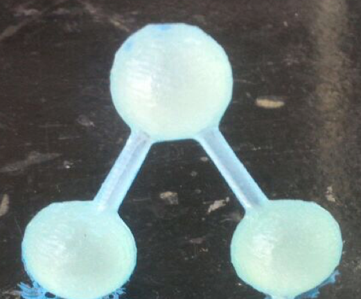
harden, for 24 hours and the results were perfect. The Final step was
to obviously remove the mold from the clamp and remove the epoxy
casting from the mold. Bellow, are the steps of pouring the epoxy into
the mold and the finished product:
Note:
The ratio of epoxy to hardening agent is 100:30 by weight