Electronics Design
This week purpose is to get familiarized with circuit designing software and redraw a circuit board drew by Dr.Neil also because this is definitely essential skill that we'll need for the final project.
Why Eagle ?
- I used Eagle because I already used it for couple of times, so I have minor knowledge about it.
- I'm a SolidWorks user, so I was concerned on the long term to use the collaboration between SolidWorks and Eagle in simulation.
- Also, because Dr. Neil pointed couple of times that Eagle is powerful software and probably we'll end using it.
Downloading and Setting up Eagle Software:
I downloaded Eagle Software from their official website and took the student license.
After that I downloaded the Fab academy Eagle library and added it to Eagle libraries directory and in the video below you can see how:
*video*
The assignment is to redraw the echo hello-world board and add a LED and a button.
Eagle Usage:
First, it's better to use the provided Fab library that you'll find on the archive website.
Here's how to download the library from the academy website, save it, import it into eagle.
Now you've successfully imported the Fab library.
A circuit diagram (electrical diagram, elementary diagram, electronic schematic) is a graphical representation of an electrical circuit. A pictorial circuit diagram uses simple images of components, while a schematic diagram shows the components and interconnections of the circuit using standardized symbolic representations. The presentation of the interconnections between circuit components in the schematic diagram does not necessarily correspond to the physical arrangements in the finished device.
Unlike a board view which for example in eagle the board view is where you put the components arrangement and how the traces are connected.
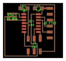
The next step is to draw a schematics and add the electronics board components and here's how:
Components and tools used:
- 1 x FR1 (Copper PCB Board).
- 1 x 1/64 inch end mill bit for the traces.
- 1 x 1/32 inch end mill bit for cutting the board.
- 1 x double tape.
- 1 x Roland Modela MDX-20
- 1 x Soldering Station.
- Soldering wire
- AVO multimeter: to check if there's any short circuits.
- Electronic Components:
- 1 x Attiny 44 SSU.
- 1 x (2x3) pin header for AVRISP
- 1 x (1x6)pinheader for Rx,Tx,VCC,GND
- 1 x RGB led.
- 1 x Push Button.
- 1 x Resonator .
- 1 x 1 uF Capacitor.
- 1 x 10k Resistor
- 1 x 499 Resistor.
- Optional Component:
- 1 x 10k Resistor
Before you start there's an optional component which acts as pull-up resistor for the push button.
you can simply connect without it and use the internal pull-up resistor in the arduino. That's why I wrote its
optional.
In order to add your components to Eagle:
After adding the components we have to join components together using the Line button which's beside the T text button, and you'll have to use it too much; that's why I made a hotkey for the line command to save time and mouse clicks.
Here's how to assign a hotkey:
Here's how to connect the components legs together yet with a neat way to avoid complications and to ease tracing the lines back; if you made a mistake while connecting.
Personally I prefer avoiding direct connections; Because it makes my eyes confuse.
In this video I meant to do the wrong way at first, so you should use the Name command instead of changing the name using the Info command to link the lines together.
After connecting all components legs and before you start switching to the board view to arrange the components physically and make the final PCB dimension you might need to specify the value of resistors; because you have several of them with different values for example then switch to the board view:
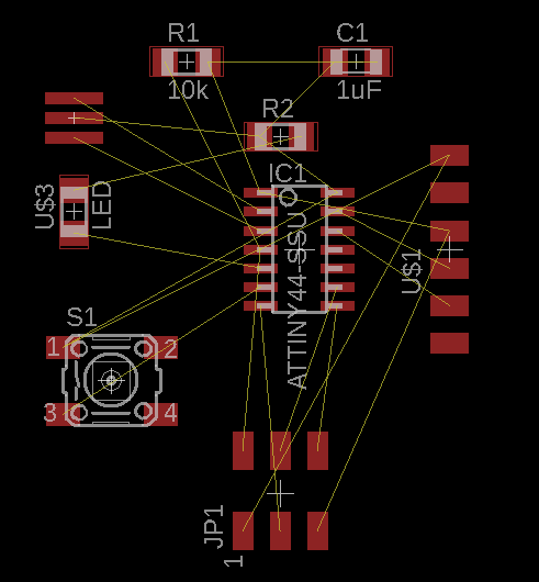
Switching to board view:
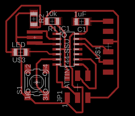
After connecting all the airwires (the yellow wires that are visible in the board view because of the schematics connection) you might not find you board look like mine, but after several arrangements I've found out that this's the optimal position. You can decrease the line width I used to decrease the board size but I don't recommend that cause I felt that this was the optimal and if it's a must you can decrease it in certain place then get it back to the original length:
My line width is 16 mil. EXCEPT for the line below the LED which's 12 mil.
Before:
After:
Next Export the file and resize it, and here's how:
Here's the output of this video by using only the top layer it's better to uncheck the rest of the layers.
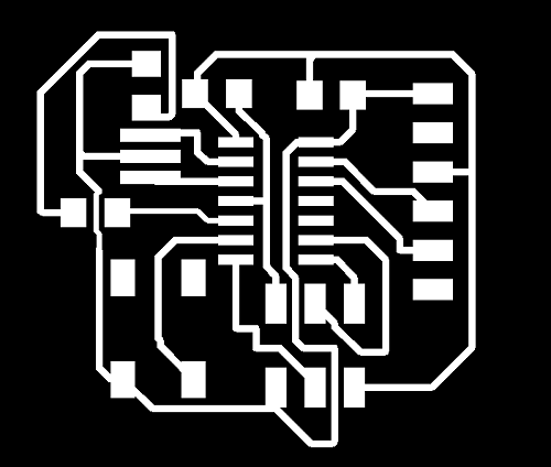
you might wonder why I exported the file as monochrome (Black & White), the difference between the white and black is the part fabmodules see and make the traces upon it.
Now you might ask yourself whether your traces are too close and the machine will go cut them perfectly or will cut the traces you want because they're too close or maybe over lapping, there's a test called Design Rule Checking (DRC) and the FabAcademy website provided prameters for the DRC test and here's how to do it :
After having the traces file you should add the outer frame file which you need to cut the board in any shape you want out of a big copper board such as: Circle, Square, any solid picture such as whale or any vector picture.
so here's how:
After exporting the image you have to add margin; Because the original file doesn't have black & white edge that the the router can cut, so you have to make this tedious process below add margin as a reference for the cutting and have the cutting file itself.
I used GIMP which's a cross-platform image editor available for GNU/Linux, OS X, Windows and more operating systems. It is free software, you can change its source code and distribute your changes, so anyone can use it.
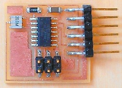
Lastly, If you want to get through the machining part you should refer to Electronics Production week for details.
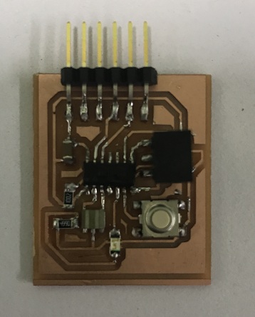
When I tried to program the board it refused to be programmed or even get the bootloader burnt.
so I tried several things to make it work:
- I checked each component alignment and soldering.(Nothing was wrong in this step.)
- I checked that the my FabISP is working be programming another board. (and it was working)
- I checked the voltage using an Avometer that the ATTiny IC is receiving the normal logicl volate (5v), which's another way to ensure that everything is soldered correctly. (and the voltage wasn't the problem as well)
So I decided to make another board, because I was out of solution for debugging the board!
The New Board :
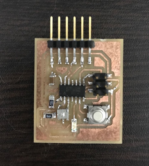
and finally it worked and got programmed several times with different functionalities.
To learn more about programming in details, please check Embedded Programming documentation.