Embedded Programming
You might wonder what is a Datasheet?
Datasheet is the biography and manual of any electronic component They explain exactly what a component does and how to use it. I do believe that before using any components you must read it's data sheet because it holds important information like Powr supply requirements, Pins Configurations and descriptions, Electrical ratings and Schematic of the IC circuit.
Lastly, I'll tell you what I've read before in a book called "Electronics for dummies 9 in 1" for the author Doug Lowe
He Said: "in datasheet you'll find every detail related to components starting from information you'll need as a hobbiest to information you'll need if you're a rocket scientist".
Reading Datasheet:
So I started by reading the ATTiny 44 datasheet, because I'll need it in programming to select the pins. My advice, this Spark Fun tutorial is more than amazing and made for beginners and describes who can a totally newbie get the utmost out of the datasheet.
First of all, the first page is one of the important pages for any component and probably might cause you to judge whether you'll continue reading it or not.
For instance,
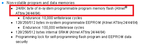
Memory:
(2/4/8k) -------respectivley------> ATTiny (24/44/84)
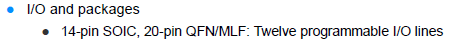
Number of pins:
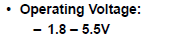
Operating Voltage:
we use usb port which provides 5V which's OK :D
The essential things that you MUST look on:
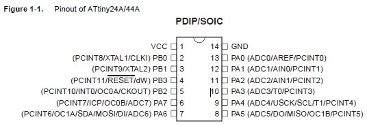
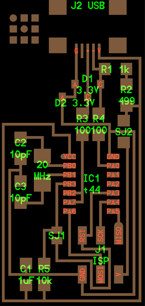
Pin Configuration:
This's through hole components configuration
Surface mount configuration
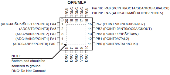
You might wonder what's the differece between labels on the pins, and why most of them are separated into 2 categories "PA" and "PB".
These designations are important especially if you are programming with C language, as you'll be required to define the Ports and the data in it. In "Pins description" section you'll find a brief description about each pin.
Pins description:
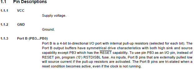
Lastly, the further you go down the more detailed and technical you get exposed do and most hobbiests tend to use only 3 or 4 pages sometimes they only use the first page.
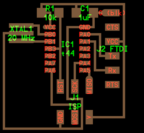
Connections:
Before coding you must wire the FabISP and Hello Echo Board.
luckily this's not a hard job to do and here's how :
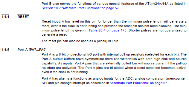
All you have to do is having either (Female-Female) jumpers or the specialized insulation-displacement contact (IDC) connector which's more neat and organized, especially because this circuit pins are already organized.
Female-Female Connector:
IDC Connector:
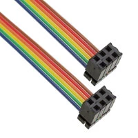
You have to connect the each pin header to its similar pin in the other board.
For Example:
V -----> V
GND ---> GND
MOSI --> MOSI
Coding:
I followed this brilliant and descriptive tutorial for Highlow tech which I highly recommend.
First, you have to install Arduino IDE which's the platform we'll be using to program our attiny44 using ArduinoC language.
However, there's a tedious procedure you must pass through to get the IDE ready to upload on the ATTiny:
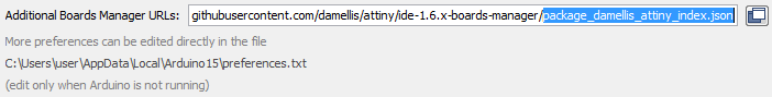
- Open the preferences dialog in the Arduino software
- Find the “Additional Boards Manager URLs” field near the bottom of the dialog.
- Paste the following URL into the field (use a comma to separate it from any URLs you’ve already added):
- Click the OK button to save your updated preferences.
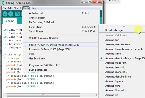
- Open the boards manager in the “Tools > Board” menu.
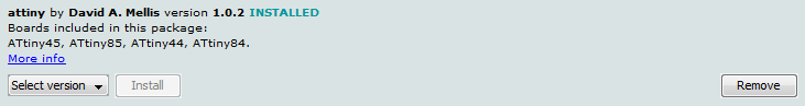
- Scroll to the bottom of the list; you should see an entry for “ATTtiny” an install button should appear. Click the install button.
- An install button should appear. Click the install button. The word “installed” should now appear next to the title of the ATtiny entry.
- By this step you should have the ATtiny boards in the "tools" tab
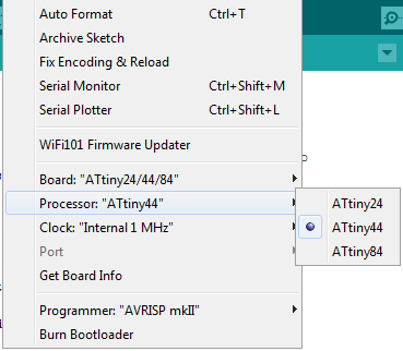
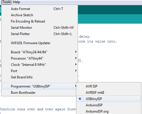
- open "Tools" menu and select the board "ATtiny24/44/84"
- Then select your processor (ATtiny 44)
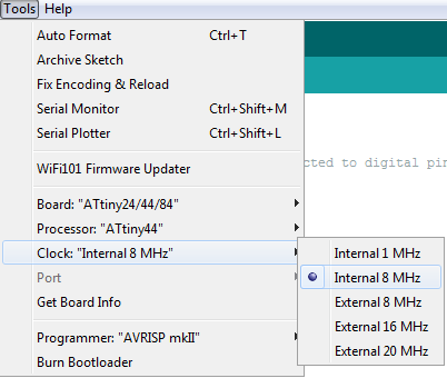
- Also, you have to choose your clock speed which's in our case is 8 MHz or you can use the 20 MHz external ONLY if you have the hardware setup on the board which not all boards have!
- To be ready to upload any code, you have to choose your programmer which's the easiest Tools > Programmer menu > USBtinyISP (e.g. “Arduino as ISP” if you’re using an Arduino board as the programmer, USBtinyISP for the USBtinyISP, FabISP, or TinyProgrammer, etc).
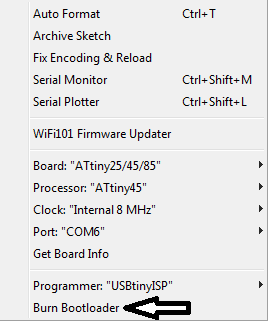
- After that, you have to burn bootloader, this configures the fuse bits of the microcontroller so it runs at the 8 MHz desired.
After selecting all these options I tried to upload a sketch to ensure that the settings is correct and everything is connected, yet I got this error message.
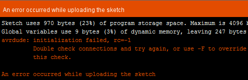
So I double checked my IDC connection, soldering and measured the voltage entering the IC and it was ~5v and nothing was going wrong, yet couldn't get rid of the error, so I made a new Hello Echo board.
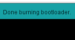
Surprisingly, it worked from the first time and the bootloader got burnt.
Then I started writing codes for the board:
Code 1:
This code was made to test the basic blinking function and the pin was selected based on my board and attiny configuration, so it will only blink on and off.
.jpg)
int LED = 8; // LED Pin.

void setup() {
  // initialize digital pin (8)---> LED  as an OUTPUT.
  pinMode(LED,OUTPUT);
}

// the loop function runs over and over again forever
void loop() {
  digitalWrite(LED, HIGH);   // turn the LED on (HIGH is the voltage level)
  delay(100);                       // wait for a second
  digitalWrite(LED, LOW);    // turn the LED off by making the voltage LOW
  delay(100);                       // wait for a second
}
Code 2:
This code was a bit advanced cause it includes iterations that differs in the LED behaviour to test my understanding of coding in arduino, so it will blink on and off as well, but with different intervals as you can see below:
int LED = 8; // LED Pin.
int var = 0; // Variable variable made to control delay.

void setup() {
  // initialize digital pin (8)---> LED  as an OUTPUT.
  pinMode(LED,OUTPUT);
}

// the loop function runs over and over again forever
void loop() {
  while ( var != 1000) {     // While loop which waits for the condition to be FALSE (ex. 1000,1001,..etc)
  digitalWrite(LED, HIGH);   // turn the LED on (HIGH is the voltage level)
  delay(var);                // wait for a second.
  digitalWrite(LED, LOW);    // turn the LED off by making the voltage LOW.
  delay(var);                // wait for a second.
  var+=100;                  // Increments the variable (var) each time the loop works.
  }
  if (var == 1000) {        // If condition acts as an automatic reset to the Variable (var).
    var = 0;                //set variable (Var) value equal to 0.
  }
}
Code 3:
This code is different than the old ones, it will blink on and off upon pressing on push button. My push button is connected using the internal pull up resistance so it becomes active low (Trigger for ON = 0 not 1)
int LED = 8;   // LED Attiny Pin.
int PB  = 7;   // Push Button Attiny Pin.
int state = 0; // Variable for the Push button to store its value into.


void setup() {
  // initialize digital pin (8)---> LED  as an OUTPUT.
  pinMode(LED,OUTPUT);

  // initialize digital pin (7)---> PB  as an INPUT.
  //INPUT_PULLUP uses the internal push up resistor.
  //when you don't have it in your hardware.
  pinMode(PB,INPUT_PULLUP);

}

// the loop function runs over and over again forever
void loop() {
    state = digitalRead(PB);    //reads the value of the PushButton pin,
    if (state == 0){            // If condition acts as a condition to either turn the LED ON or OFF ( "== 0" in our board) means if the condition is met.
    digitalWrite(LED, HIGH);    // turn the LED on (HIGH is the voltage level)
    delay(2000);                // wait for a second.
    }
   else {
   digitalWrite(LED, LOW);     // turn the LED off by making the voltage LOW.
   }
}