Embedded Networking and Communications
Task Requirments:
- Design and build a wired and/or wireless network connecting at least two processors
- Describe your design and fabrication process using words/images/screenshots.
- Explain the programming process/es you used.
- Describe problems and how you fixed them.
- Include original design files and code.
Idea:
The Idea is to connect the 3 boards i previously made (Hello Echo board , Laser Phototransistor board , Servo Motor Board ) and adjust there codes to make them communicate and prepare them for my final project.
I will use the button in the hello echo board to initiate the communication and send signal to the sensor board to starting counting then the sensor board will send signal to the servo motor board to flip when the preset count is reached.
Codes:
I decided to use the MISO/SCK pins as RX/TX for all the boards
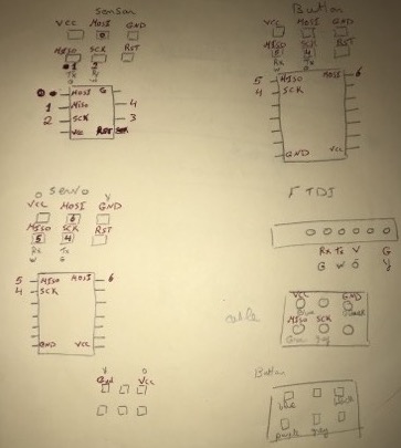
First thing i sketched the pinouts of my boards to facilitate identification of pins ad am working on three boards and it migh be confusing.
Button Board:
The Coding of this board was simple and straight forward, I included the softwareserial library from arduino and checked the button status, if pressed, serial print starting and send 'O' for on, please note O is in single quotation and not double, we will talk about in the second board. Then it reads from the sensor board and waits for'R' for reading which lights on the led
Sensor Board
This is the main board that will run the main program of my project.
I uploaded a simple code to test the communiaction witht the button board, so i used the serial read command to wait for the char "O" and then turn on the laser diode and serial print the sensor value.
The Board didn't respond i checked the connection and made the code serial print Hello on it's start, everything was ok and hello was printed but no respond to the buttom board
I connected the board directly to the computer through FTDI and tried to send the "O" character through serial monitor but no response, After long search and help from Abulhaggag "Credit must go to him", we found out that the problem is that Strings are always defined inside double quotes ("Abc") and characters are always defined inside single quotes('A'). So i change the quotes of the char O from"O" to 'O' and it responded perfectly.
Then I Started to develop the final code of the board to fit my final project
Logic of the code:
The photo resistor reads a value of 1 to 10 when laser is pointed to it, and a value of minimum 600 in the brightest light, so i decided to work in the range if 30 to 100. For more info about sensor readings please refer to Input Devices Assignment.
I want the board to monitor the change of the sensor value in these values and translate this change as cap passing and starts counting, then serial send 'F' to the servo board when the preset count is reached"10" and then start counting again, also when the board starts reading it serially sends 'R' to the button board to ensure it received it's command.
- I made a variable called CapCount to store cap counts and preset it to zero.
- I made a variable called counttrigger and set it to 100, this is the value that says cap is passing.
- I made a variable called resettrigger set it to 30 , this is the valuew that says the cap has passed.
- I made a boolean called currentstatus and set it true, this value is made to store the current status and changes with every count to make reading stable and only counts when status change.
So i made a serial read command to wait for 'O' to initializen then:
- I took 5 readings of the sensor and divided them to take the average for accuracy
- If the current status is true and the sensor value is bigger than the trigger value, i changed the current status to false to stop counting and added one cap to the cap count.
- Else if the current status if false check for the resettrigger if sensor value less than resettrigger, change current status to true to start counting again.
- Lastly i made if condition if capcount = 10 reset capcount and serially send 'F' to the servo board to flip angle.
Problem and solution:
I made the code in to loops one which checks for serial input "Void loop( )" and then calls for the other loop "void checkinput( )" if the condition is met.
First when i tried this code it only made on count and stoped waiting for the serial input again, so ihad to call the function "Checkinout()" at the end of the void checkinput() loop to make the code loop and not wait for serial input again.
And here is the final code:
Servo board:
This code also was a straight forward one like the button, i made a serial read function and if condition if 'F' is sent move to angle 90.
Wiring:
I connected the TX of the buttob board to the RX of the Sensor board and the TX of the sensor to the RX of the Servo Board.
And here is the result.