Embedded Programing
Task Requirments:
- Document what you learned from reading a microcontroller datasheet.
- Program your board
- Describe problems and how you fixed them
- Describe the programming process you used
- Include your code
Reading Data Sheet
I wanted to know the pinouts of the attiny 44 and make sure that the pin i connected the button have internal pullup resistance because it's connected to the ground, so i googled the data sheet of attiny44 and found this This data sheet, i scrolled down for the pinout and found my button which is connected to pin number 5 is named "PB2"
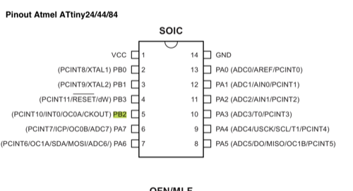
I searched the data sheet with Control F to jump to the specs of this leg, and found that this is bidirectional "i.e In and out" with internal pull up resistors, so i can set a my button to be always high depending on the internal pull up resistor.
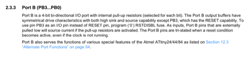
Because i was planning to use arduino IDE, so i had to know the pinout names in arduino, so i googled Attiny44 arduino pinouts and found this photo
Programming
Connecting the board
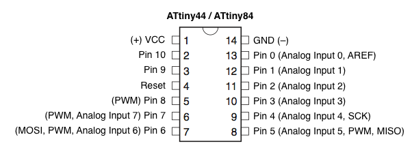
I connected the Hello Echo Board to the Fab isp with ISP cable.
I don't have FTDI cable so i connected the board Vcc and GND to external power supply.
Burning bootloader
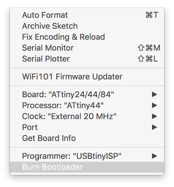
I used arduino IDE to burn bootloader:
- From the tools menu
- Choose board: Attiny 24/44/84
- choose processor: Attiny 44
- Choose clock: External 20 MHz
- Choose programmer: USBtinyISP
- Hit Burn Bootloader
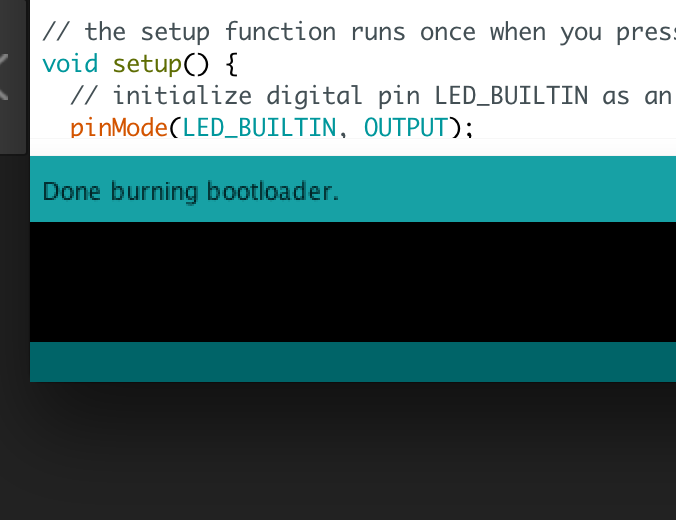
If the process is ok, you should see "done burning bootlader" on the down left corner of the screen.
Coding
Blink a led:
to test the board and the coding i uploaded the blink a led code and changed the led pin from 13 to 7 "as per arduino pinout" and uploaded the code.
	/*
    Blink
    Turns on an LED on for one second, then off for one second, repeatedly.

    This example code is in the public domain.
     */

     // Pin 13 has an LED connected on most Arduino boards.
     // give it a name:
     int led = 7;

    // the setup routine runs once when you press reset:
    void setup() {
    // initialize the digital pin as an output.
    pinMode(led, OUTPUT);
     }

     // the loop routine runs over and over again forever:
    void loop() {
    digitalWrite(led, HIGH);   // turn the LED on (HIGH is the voltage level)
    delay(1000);               // wait for a second
    digitalWrite(led, LOW);    // turn the LED off by making the voltage LOW
    delay(1000);               // wait for a second
     }
Minor failure:
The Led didn't Blink !!
- I used the multimeter to measure voltage comming out of pin 7 and the voltage was blinkning, so no problem with the MCU nor the code.
- I checked the led with the continuity on the multimeter and it was ok.
- I suspected the soldering of the LED so i resolder it and it was ok !
Push Button to light the LED
I uploaded the button code from the arduino basic examples library, i changed the button and LED pins according to my connections, and i changed the button setup to be INPUT_PULLUP to used the internal pullup resistor in the leg.
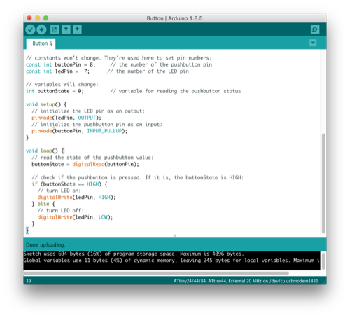
The Led was let by default because i pullued up my button to be always high, so i had to reverse the code so the led will be high if the button is low.
And here is the final code
// constants won't change. They're used here to set pin numbers:
const int buttonPin = 8; // the number of the pushbutton pin
const int ledPin = 7; // the number of the LED pin
// variables will change:
int buttonState = 0; // variable for reading the pushbutton status
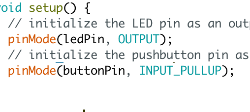
void setup() {
// initialize the LED pin as an output:
pinMode(ledPin, OUTPUT);
// initialize the pushbutton pin as an input:
pinMode(buttonPin, INPUT_PULLUP);
}
void loop() {
// read the state of the pushbutton value:
buttonState = digitalRead(buttonPin);
// check if the pushbutton is pressed. If it is, the buttonState is HIGH:
if (buttonState == HIGH) {
// turn LED on:
digitalWrite(ledPin, LOW);
} else {
// turn LED off:
digitalWrite(ledPin, HIGH);
}
}