Week 19
Final Project Development
Software Used
AutoCAD, Makerbot, B9 Creator, Maya, Adobe Illustrator, Google Chrome, Sublime Text, Photoshop, Git, Art Cam, Grbl Controller, Rhinoceros, Arduino, RDWorks, Sketchup


Files used:
Arduino code for sensor .INO DownloadSensor Arduino Library 1 .CPP Download
Sensor Arduino Library 2 .H Download
Hexaduino Board Eagle .BRD .H Download
Hexaduino Schematic Eagle .SCH Download
Hexaduino Gcode milling file .NC Download
What is the deadline? How much time do I have left?
In order to have a working final project for the upcoming deadline (t-minus 12 days), I had to create a schedule and assign tasks within the remaining time frame. First I listed the tasks that I needed to complete and divided them into design, manufacturing and programming:What tasks have been completed and what tasks remain?
DESIGN- design container
- outer shell
- interior insulated case
- design cooling and heating tower shells
- design case for cables, boards, pins and components
- design base plate for recessed lighting
- design flask insert - design schematic for timed lights
- design arduino code for timed lights
- design housing for peltier temperature regulator components
- design schematic for peltier temperutare regulator
- design schematic for relay power regulating board
- design schematic for fabduino
- design Arduino code for switching on peltier temperature regulators
- design flask insert
MANUFACTURING
- laser cut container, cooling tower shells, base plate, case for peltier temperature regulator
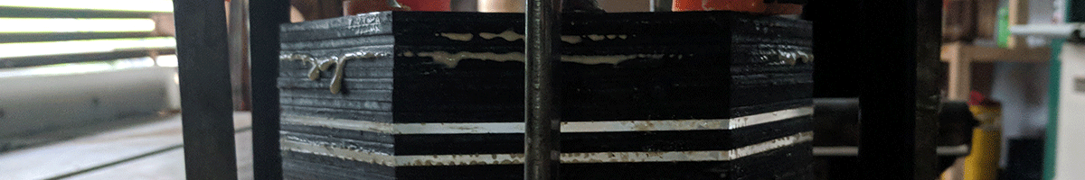
- join, glue and clamp layers of container and base plate
- cut edge profile angles where edges of the mecon will meet ("mecon" is what Buckminster Fuller called the truncated octahedron, also a 14-faced Archimedean solid
- assemble the container by joining the tiles
- assemble the tower shells
- assemble the case for cables and boards
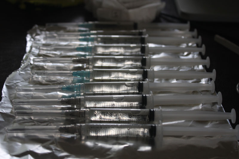
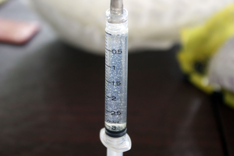
- 3D print flask inserts
- install the LED strip and wires leading from the base plate to the relay board
- assemble the housing for tower #1 peltier temperature regulator
- position the side 1 fan
- install a fan-stop layer to secure the fan within the case
- position side 1 heat sync
- position the peltier support
- position side 2 heat sync
- position side 2 fan
- install a final fan-stop layer to secure the fans, heat syncs and peltier pressed against each other
- assemble the housing for tower #2 peltier temperature regulator
- position the side 1 fan
- install a fan-stop layer to secure the fan within the case
- position side 1 heat sync
- position the peltier support
- position side 2 heat sync
- position side 2 fan
- install a final fan-stop layer to secure the fans, heat syncs and peltier pressed against each other
- connect the ground and voltage cables of the fans and peltier devices to the relay board by feeding them through the tower shells and into the case for cables and boards
- connect the relay board to the fabduino
- fit the LCD screen into the front slot and connect the 12 pins to the fabduino
- fit the temperature sensor into the mecon through the base plate and connect the ground, voltage and input on the fabduino
- connect the fabduino to a 5V power supply
- connect the relay board to a 12V power supply and the pin to the fabduino
-plug in the power supply
PROGRAMMING
- burn fabduino and install code for:
- temperature regulation code within a determined temperature degree range
- turning the lights on and off
- displaying temperature sensor information on LCD
What have you learned?
I am really excited about the peltier units and the results of my research inspired by this class. I found several instances of peltier cooling devices but they had never been used for my application specifically. One thread mentioned someone wanting to make an "orchidium" but the conversation ended without any results posted. This technology is something completely new to me and I wonder if it was created in the first place to simulate HDs overheating so that manufacturers could design better cooling systems. I would also be very interested to see what the difference is between local market peltiers and some military-grade peltier devices. There must be some pretty interesting devices/applications for the technology.The peltier temperature regulator is just an example of what can be done with some spare computer parts, but the design of a container and interfase for automating the project was a challenge that I enjoyed.
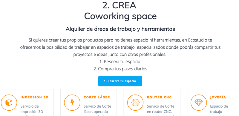
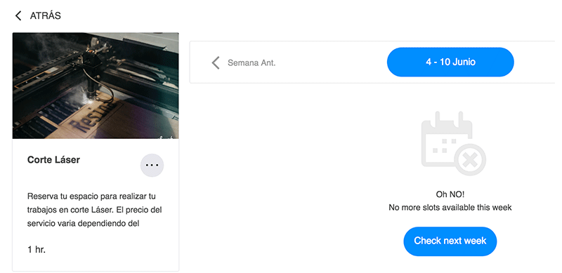
Proper documentation and file creation helped me save a lot of trouble going back and forth from my house to the shop. I checked my files at home and sent them via the Lab's google drive so that I could put download them to a USB and use them on the Laser cutter. Also it is important to reserve time with the lab for using certain equipment, so I reserved a 2 hour time frame on saturday. For laser cutting this kind of scheduling was important because the laser gets used for commercial projects as well as student projects from other universities.
How will I complete the remaining tasks in time?
I have completed all of the design files for the final project and need to manufacture and program the container. I feel confident with all of the machines in the shop and we have enough bits and tools to be able to make almost anything.The only part of the project in which I experienced a delay was in the PCB milling. I personally designed a hexaduino for my project using the schematic for the fabduino. I have been able to cut them out on our PCB mill but the mill isn't giving consistent results. There are times where it will plunge into the z-axis even though there is no code telling it to do so. Then upon the next attempt to run the toolpath it will perform the correct toolpath.
What hasn't worked?
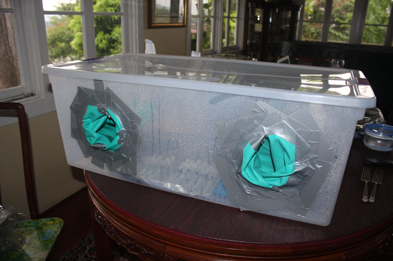
One of the original goals of the project that I was unable to resolve was hermeticity. I can create a climate controlled container but if I want it to be economical and perform that function, it would have to be something much smaller that could fit into a pressure cooker and withstand the heat and pressure. It would then have to be able to fit into a laminar flow hood to be able to insert spores/seeds into the container while maintaining its hermeticity. In addition, the air coming into the container would have to be filtered, otherwise the entire case would have to be sealed and have direct contact points to the peltier unit to heat or cool the container. That would then require a much more complicated mold and fabrication process as the final materials would have to be made of metal and glass.Another component that I considered making was gaskets in between the joints of the container to create a tighter seal for temperature insulation. To do this I would make a mold of the square and hexagon with 100mm sides to place inbetween each layer. But, this would change the shape of the tiles and I wouldn't get a clean mecon shape (truncated octahedron). I decided against using the gaskets for this version and instead used silicone to seal the inside of the container.
What has worked?
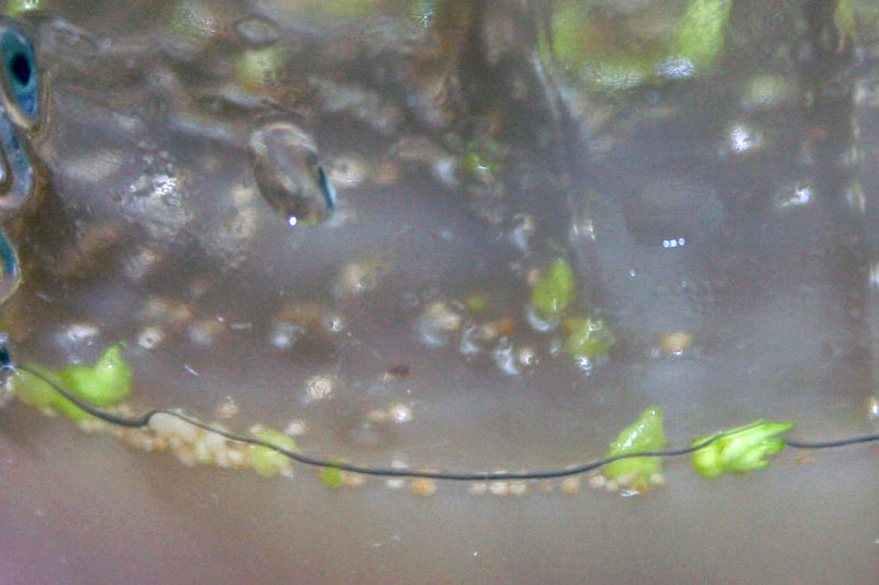
For the last two weeks of class I performed my work between my lab and house and successfuly created a working prototype of HERMET. I was very happy when the container, tower and cases fit together. I was also very pleased when we connected the peltier temperature regulators to the power source and they performed their function. I had purchased 6 peltier units (I started off without knowing mucha bout them) and so I purchased a large 12v 20A power supply with 3 circuits. This one ended up burning out one of the peltiers during testing, so I switched to a 12V/14A power supply instead. I also didn't turn the peltiers on anymore until they were connected to heat sinks and had thermal paste between the aluminum face and both sides of the peltier.What questions need to be resolved?
I have to have a working prototype by june 15, so that I can troubleshoot, re-design any files, make any improvements, adjust fan sizes, ensure the code works as expected, clean up the case and wiring and make any final design chagnes. That will give me 5 days before my presentation day of June 20 to be able to complete documentation and the presentation video and .png.
Project
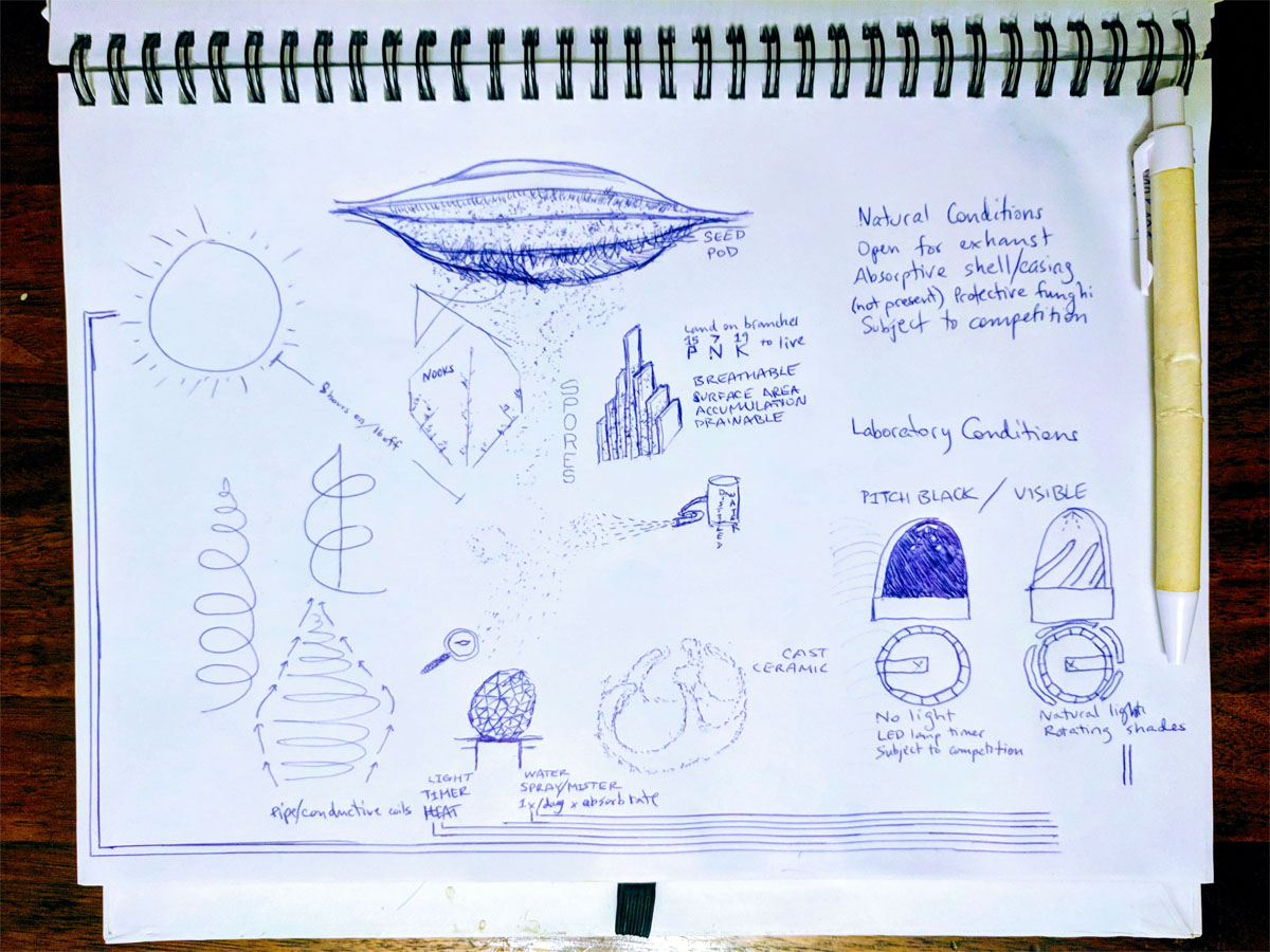
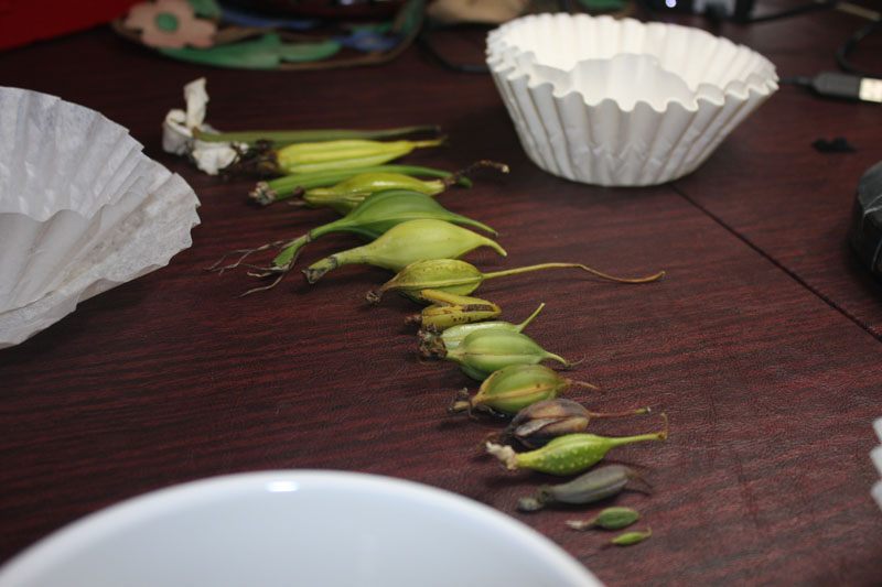
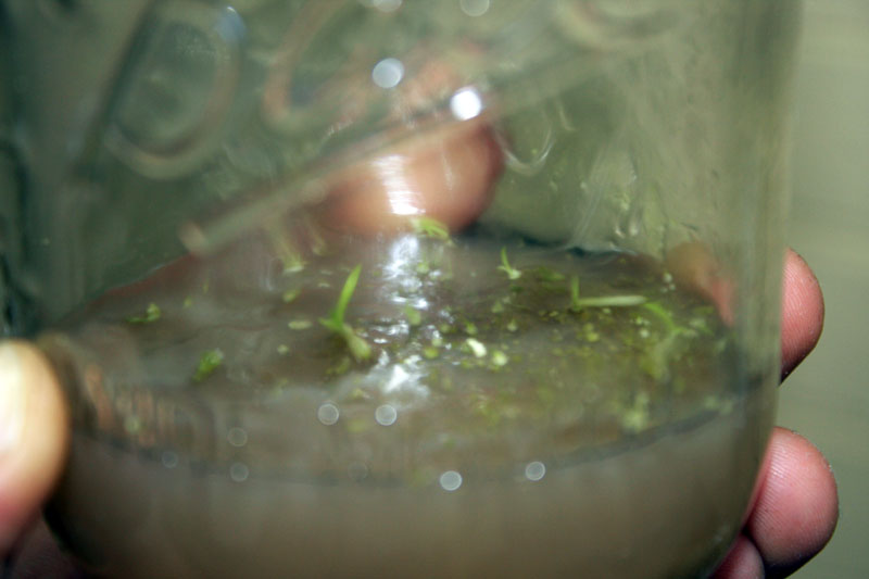
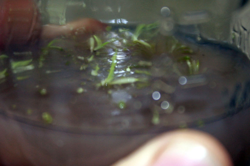
Design and prototype a chamber that can maintain the conditions needed to germinate microsopic seeds and spores in any climate.
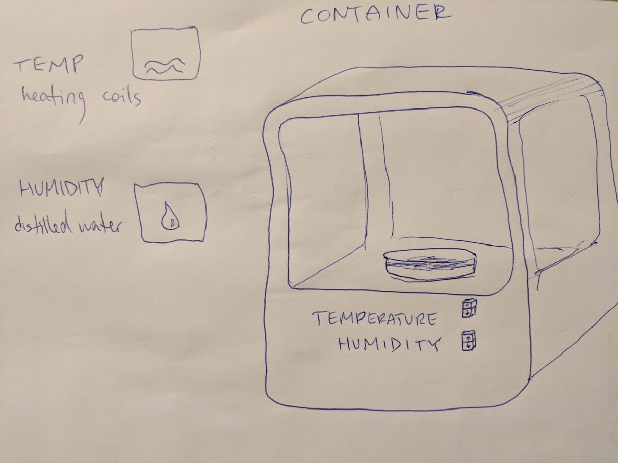
Controls
Temperature - increase or decrease from 60-85 degerees
Light - artificial on a timer scheduled to simulate growth cycles
Hermeticity - initially 100% to isolate the fragile seeds, then reduce in increments of 10% to gradually expose the seeds to the outdoors
Puncturable - in case of emergency to drain or add ingredients or water
Humidity monitor - to more precisely test and measure growing environment
Introduction
The conditions required for orchids to grow in the wild exist because of symbiotic relationships with other organisms. In order to reproduce epiphytes in laboratory conditions, equipment such as autoclaves and laminar flow hoods are used to create sterile growing environments.My mentor suggested that I look into some of the equipment that is built for the Bio Academy to see if there were any relevant examples already in use. I checked out:
Open Culture Technology
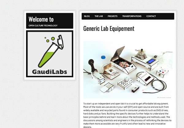
I couldn't find a device that would fulfill the function I needed so I continued by searching past student projects. I found one project :
Biosphere - by murasaki at Fab Lab Kitakagaya
A device to keep and log a closed ecosystem
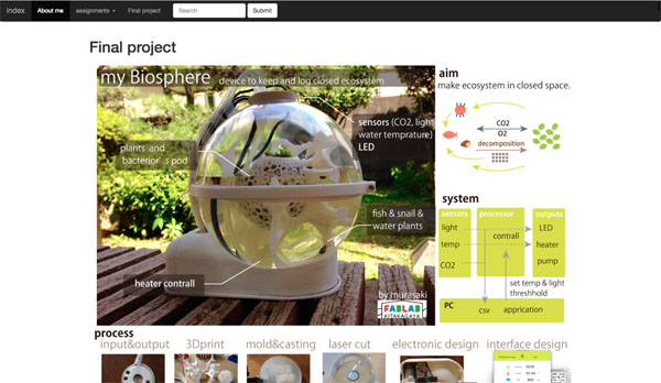
The project is a very good example of a chamber with similar controls. The main difference will be the hermetic control needed for epiphyte type plants to grow.