Week 10
Input Devices
assignment
Group Assignment
1- measure the analog levels and digital signals in an input device
Individual Assignment
1- measure something: add a sensor to a microcontroller board that you have designed and read it


 <
<
Arduino code for sensor .INO Download
Sensor Arduino Library 1 .CPP Download
Sensor Arduino Library 2 .H Download
Fabduino Board Eagle .BRD Download
Fabduino Schematic Eagle .BRD Download
Fabduino Gcode milling file .NCH Download
Hexaduino Board Eagle .BRD Download
Hexaduino Schematic Eagle .SCH Download
Hexaduino Gcode milling file .NC Download
DHT11 Sensor code Arduino .INO Download
For this assignment I wanted to create a working input for my final project. I will need to be able to know the inside temperature of the container. To generate this information I have decided to use a humidity and temperature sensor, so I looked for some information online and found a data sheet for the DHT11.
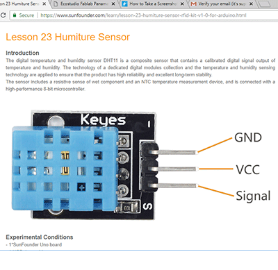
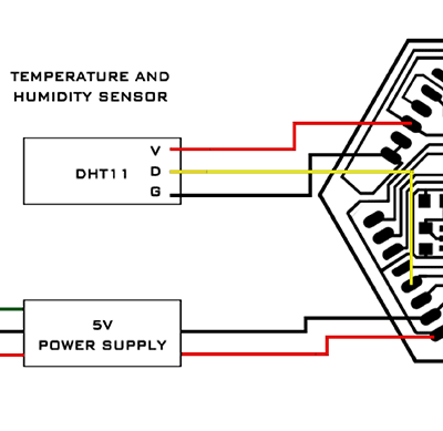
I read the data sheet and learned a bit about the physical interfacing, size and digital output. I found out that the three pins I need to connect are:
DATA (serial data output)
GND (ground)
+5V (power supply +5v)
This is how I would have to connect the pins to power, ground and allow me to program it through the port I connect it to.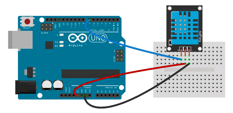
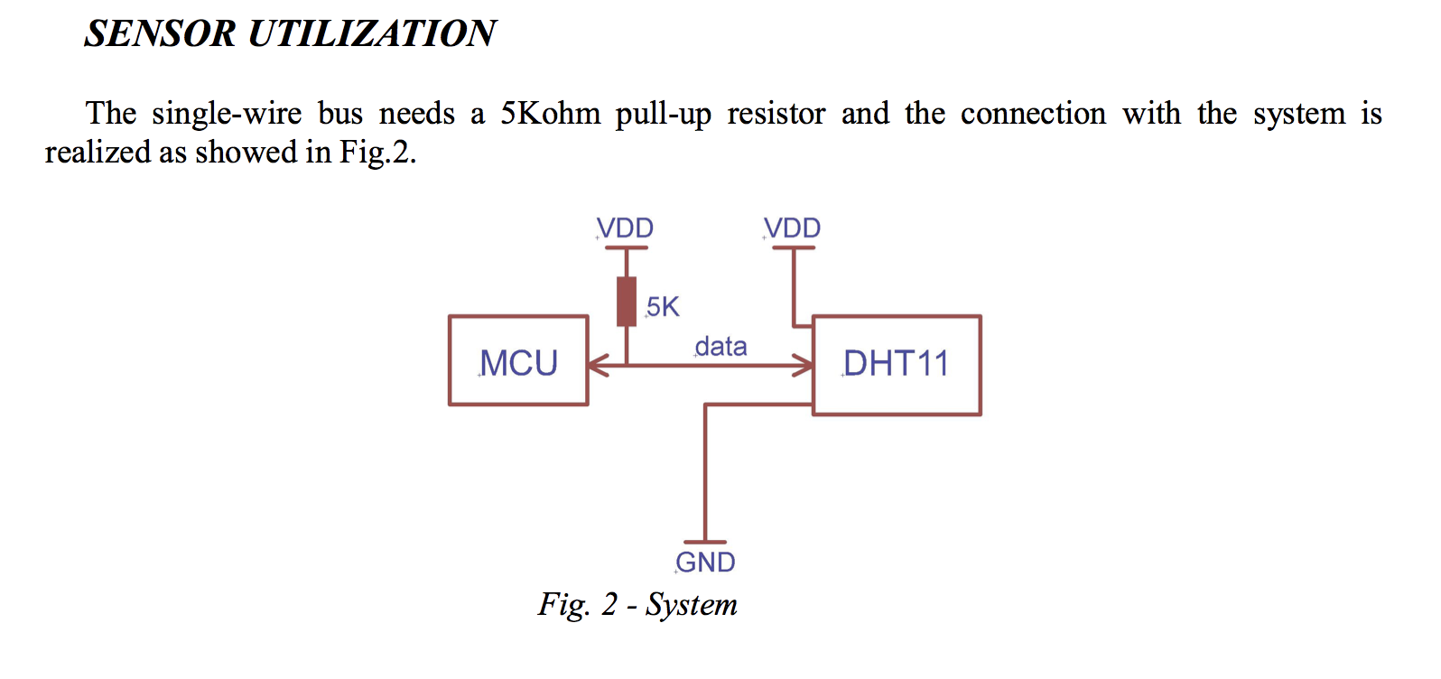
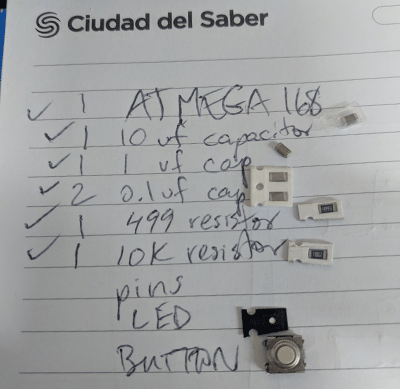
Because the sensor doesn't have a microcontroller, I need to tell it what to measure and at what intervals. To program these functions I need to build a board, or build and modify an existing board. I decided to work with the Satcha / Fabduino kit as it would be able to provide the functionality and power I need. I decided to add more pin ports to the board as I would like it to have the flexibility for adding additional functions in the future. I used the components:
(1) ATMEGA88/168
(1) 10 uF capacitor
(1) 1 uF capacitor
(2) 0.1 uF capacitor
(1) 499 ohm resistor
(1) 10k resistor
(3) 8 pin female header
(2) 6 pin male header
(1) LED
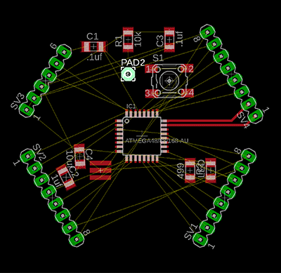
Using Eagle I laid out all my components in the schematic view and connected them with the microcontroller.
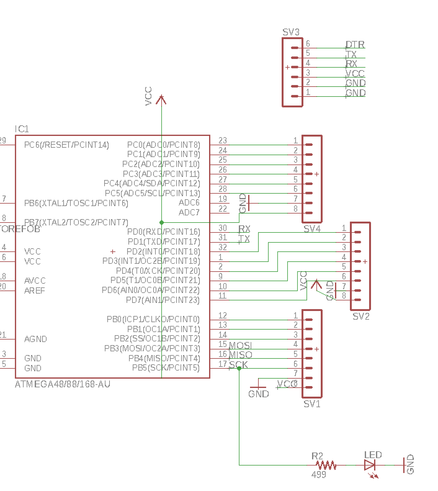
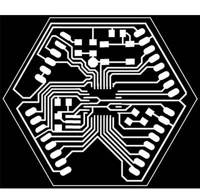
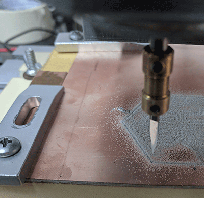
I set the route diameter to 16 and set the design rules to have 16mill clearance. I designed the board paths and once I had them complete without any overlaps I printed a real-size png of the board and exported it to InkScape. In InkScape erased the border and trial version text and also removed white circles that were exported in order to mark port/pin holes.
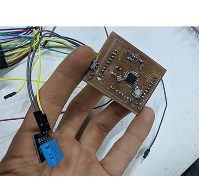
I spent the evening soldering my first fabduino with physical components from our Fab Lab inventory.
I connected the fabduino to our AVRISP mkll and unfortunately got a red light. I took it back to the soldering station and cleaned as many paths as I could but I could not get the light to turn green. I had our instructor look at my fabduino and they showed me several areas that I had to remove with a copper wire braid. After almost an entire afternoon, we were able to get the light green!
With the fabduino powered and connected to the computer I was able to burn and upload / program the fabduino (see also: Week 8).
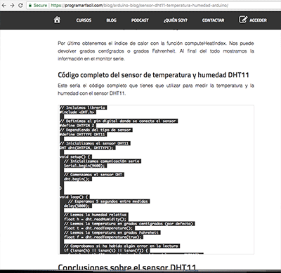
Next I needed to tell the DHT11 to produce a readout on my computer of the temperature and humidity sensor data it was sensing. I loaded the code and modified the pin ports for the humidity sensor to match the ports on my fabduino.
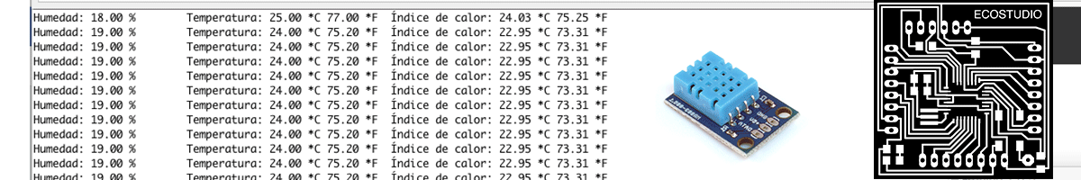
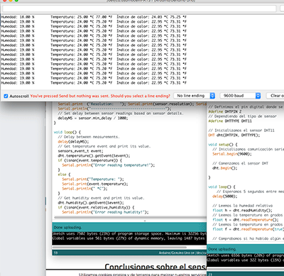
Once powered, the sensor began providing a readout of temperature and humidity every 5 seconds.
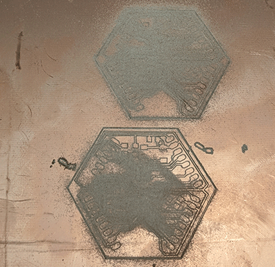
Later in the year I decided to redesign the fabduino. This process reminds me a bit of Balancing Equations in Chemistry and I enjoyed it.
1- measure the analog levels and digital signals in an input device
Individual Assignment
1- measure something: add a sensor to a microcontroller board that you have designed and read it
Software Used
Eagle, Art Cam, Grbl Controller, Adobe Illustrator, Google Chrome, Sublime Text, Photoshop, Git, Arduino <Tutorial Used
Fab Academy Week 10 - Input DevicesFiles used:
Data Sheet DHT11.PDF DownloadArduino code for sensor .INO Download
Sensor Arduino Library 1 .CPP Download
Sensor Arduino Library 2 .H Download
Fabduino Board Eagle .BRD Download
Fabduino Schematic Eagle .BRD Download
Fabduino Gcode milling file .NCH Download
Hexaduino Board Eagle .BRD Download
Hexaduino Schematic Eagle .SCH Download
Hexaduino Gcode milling file .NC Download
DHT11 Sensor code Arduino .INO Download
Walkthrough
For this assignment I wanted to create a working input for my final project. I will need to be able to know the inside temperature of the container. To generate this information I have decided to use a humidity and temperature sensor, so I looked for some information online and found a data sheet for the DHT11.
I read the data sheet and learned a bit about the physical interfacing, size and digital output. I found out that the three pins I need to connect are:
DATA (serial data output)
GND (ground)
+5V (power supply +5v)
This is how I would have to connect the pins to power, ground and allow me to program it through the port I connect it to.
Because the sensor doesn't have a microcontroller, I need to tell it what to measure and at what intervals. To program these functions I need to build a board, or build and modify an existing board. I decided to work with the Satcha / Fabduino kit as it would be able to provide the functionality and power I need. I decided to add more pin ports to the board as I would like it to have the flexibility for adding additional functions in the future. I used the components:
(1) ATMEGA88/168
(1) 10 uF capacitor
(1) 1 uF capacitor
(2) 0.1 uF capacitor
(1) 499 ohm resistor
(1) 10k resistor
(3) 8 pin female header
(2) 6 pin male header
(1) LED
Using Eagle I laid out all my components in the schematic view and connected them with the microcontroller.
I set the route diameter to 16 and set the design rules to have 16mill clearance. I designed the board paths and once I had them complete without any overlaps I printed a real-size png of the board and exported it to InkScape. In InkScape erased the border and trial version text and also removed white circles that were exported in order to mark port/pin holes.
I spent the evening soldering my first fabduino with physical components from our Fab Lab inventory.
I connected the fabduino to our AVRISP mkll and unfortunately got a red light. I took it back to the soldering station and cleaned as many paths as I could but I could not get the light to turn green. I had our instructor look at my fabduino and they showed me several areas that I had to remove with a copper wire braid. After almost an entire afternoon, we were able to get the light green!
With the fabduino powered and connected to the computer I was able to burn and upload / program the fabduino (see also: Week 8).
Next I needed to tell the DHT11 to produce a readout on my computer of the temperature and humidity sensor data it was sensing. I loaded the code and modified the pin ports for the humidity sensor to match the ports on my fabduino.
Once powered, the sensor began providing a readout of temperature and humidity every 5 seconds.
Later in the year I decided to redesign the fabduino. This process reminds me a bit of Balancing Equations in Chemistry and I enjoyed it.