Final Project: Animal Habitat - Planning and Process
Planning
As mentioned on the Initial Concept page, I finally decided to build an animal habitat for a dry (desert) style reptile. This was for a variety of reasons, but mainly the following:
- My daughter and I have owned several reptiles and I am familiar with their living requirements
- Mammals and aquatic animals require much more complicated housing requirements
- A dry, desert style environment is less likely to be harmful to electronic components
- These animals are also quite small and require smaller, more manageable-sized habitats
Towards this end, I started by speaking with a biologist/herpetologist about different dry environment reptiles and what their living requirements might be. I would NOT want to build something that might be dangerous to the animal living inside of it.
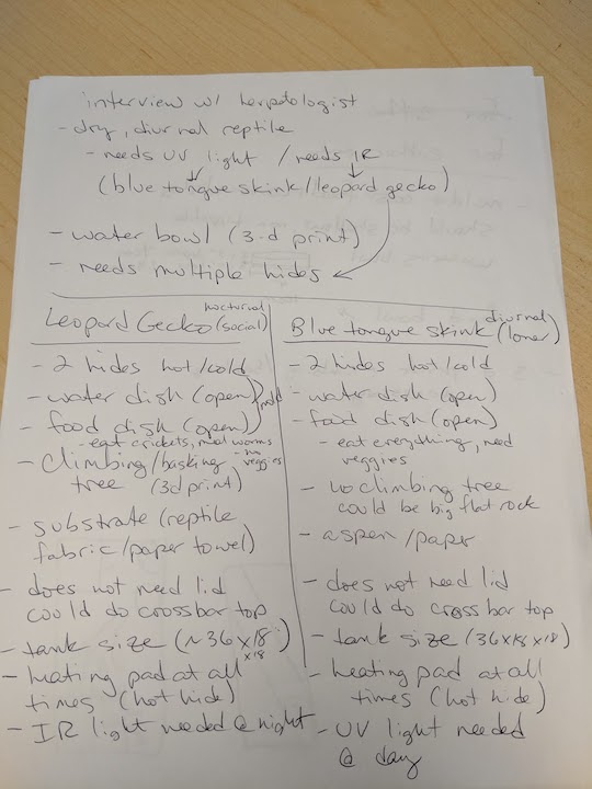
Notes page 1
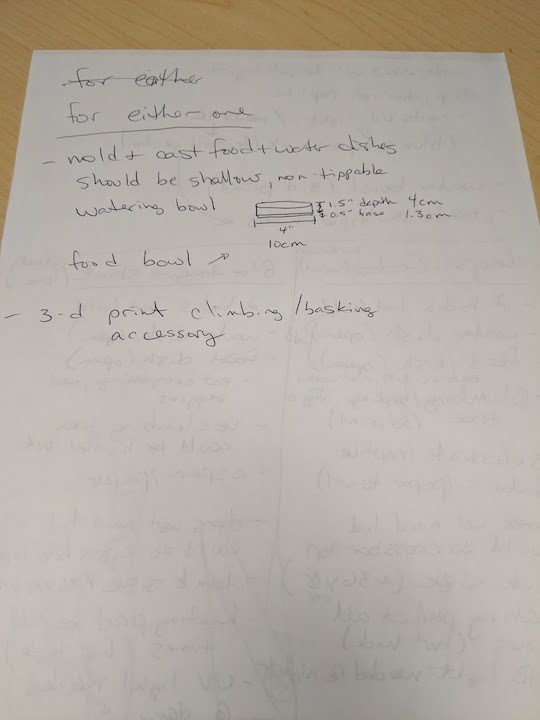
Notes page 2
Once I had it narrowed down to two types of reptiles with similar habitat requirements, I could start planning the size and scope of my habitat project.
I spoke with Saverio Silli, my Global Evaluator, who has been INVALUABLE in helping me. I outlined the following plan to him and he said, "I think this is a perfect plan, and you can write this info right in the project management documentation page :)". I love his attitude! So, following is the outline I discussed with him.
- Final Project - Animal (reptile) habitat:
- Project Management – yes, I have all sorts of sketches and designs
- CAD – I am using Fusion360, as well as Eagle and TinkerCad to design several pieces
- CAM - as above, using Fusion360 to generate toolpaths and g-code files
- Computer Controlled Cutting – I am laser cutting my acrylic pieces and vinyl cutting some decorative pieces for the sides
- Computer Controlled Machining – I will make the structural support base for the acrylic habitat on the ShopBot
- 3-D Printing – I will print a habitat feature such as a basking log or hiding spot for the animal (ETA: I 3-D printed the food/water bowl to serve as my piece to mold)
- Molding and Casting – I will create food safe molds to make the food and water bowls for the animal
- Electronics Design – I am modifying the Satshakit board to hold my ambient light sensor and removing a few unneeded pins to make room
- Electronics Production – I will make and solder the board designed above
- Embedded Programming – I will use the Arduino interface to program my modified Satshakit board
- Input – I will have an ambient light sensor on my board
- Output – when the ambient light goes below a certain level, the board will turn on the LED strip attached to the acrylic housing
- Wildcard/composite – I will make a composite piece either to go across the top of the habitat to prevent escape OR it will be a decorative piece
Process
Computer Controlled Cutting - Vinyl Cutter and Laser Cutter
I used our Silhoutte Cameo vinyl cutter to cut some decorative stickers for the sides of the habitat. I searched for free, open source silhoutte images of lizards and dinosaurs, anything that felt a bit whimsical, because that is the "feel" I am going for here.
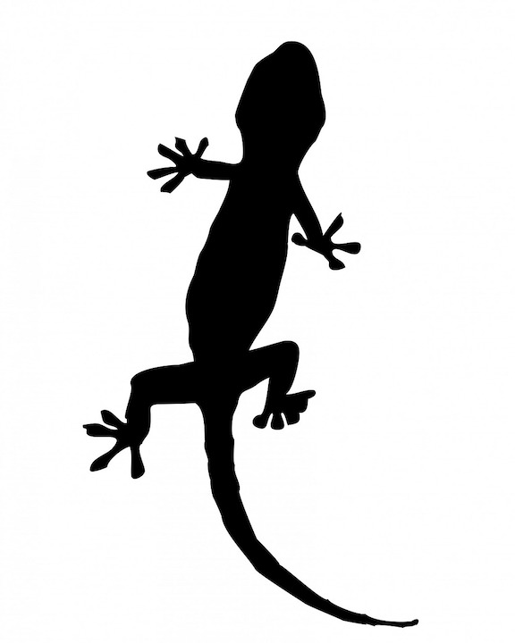
Since the tank will most likely be housing a gecko, I had to get a silhoutte of one of those
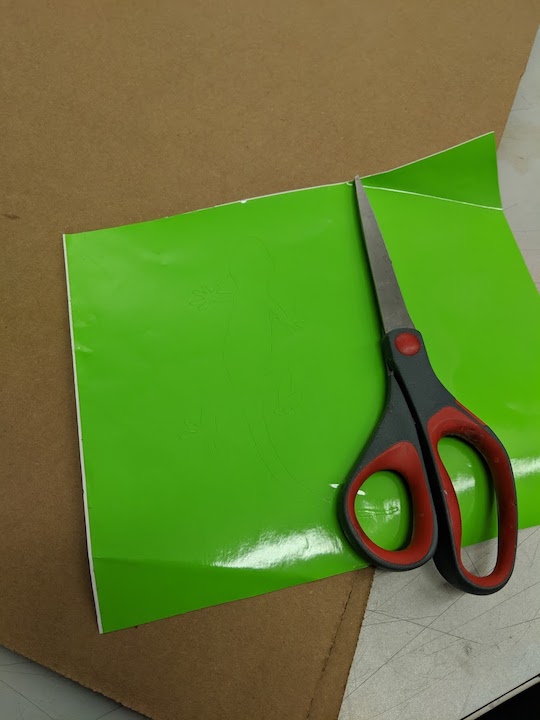
The cut gecko sticker, a little hard to see, in a brilliant green
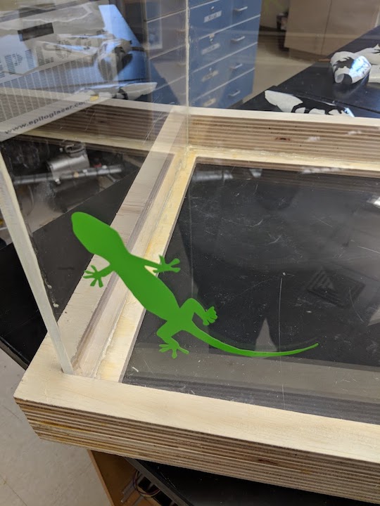
The gecko sticker in place on the habitat wall
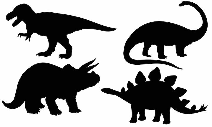
The dinosaur sillhouttes
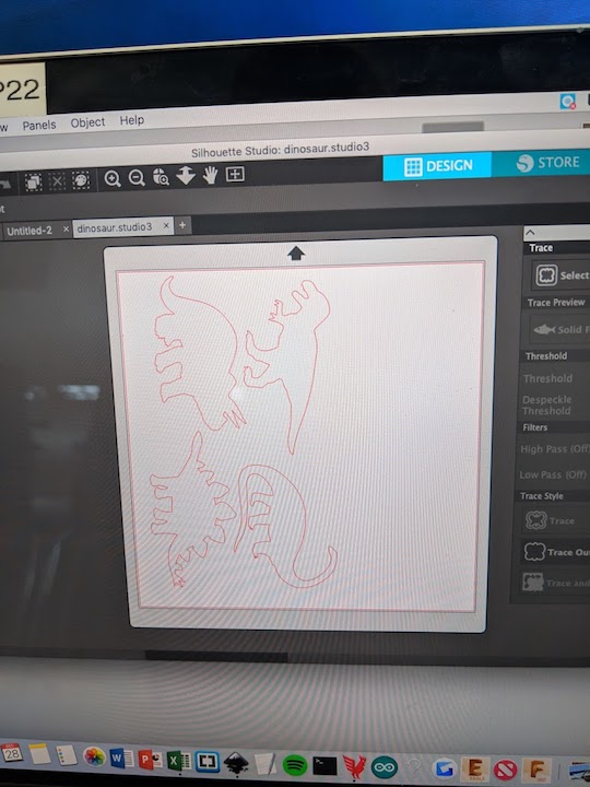
The silhouettes loaded into the software, ready to cut
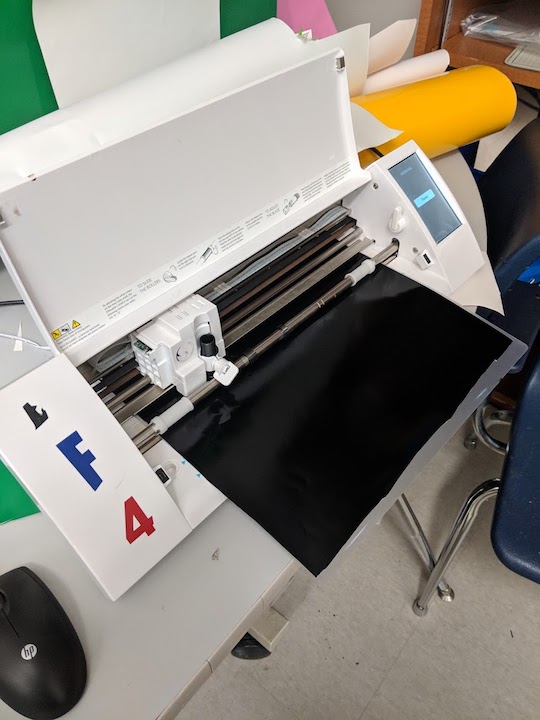
The dinosaurs getting cut. I chose black for them.
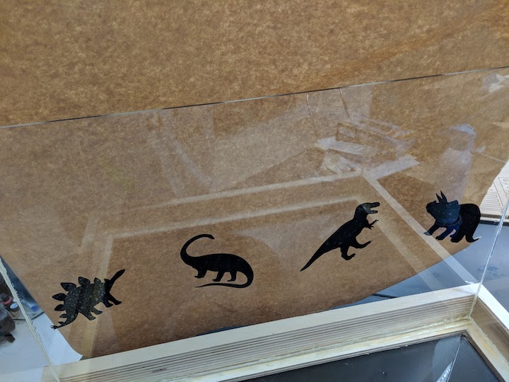
The dinosaur stickers in place on the habitat walls
The walls of the habitat were cut from 1/4" acrylic on our 50W Epliog Laser Cutter. In hindsight, I would have gone with 1/8", but in the planning phases that felt a little too thin and flimsy. However, the 1/4" is really overkill. It's too thick and it makes the habitat overall too heavy AND it was more expensive. However, it's what I had and what I ordered, and I didn't want to spend any more money, so I used it for this project. Definitely, going forward, 1/8" on any other iterations of this that I make. It required four runs of the laser cutter at 3 speed, 100 power and 100 frequency to cut all the way through. I then used an acrylic adhesive to glue the walls together and to the base, forming the main part of the habitat.
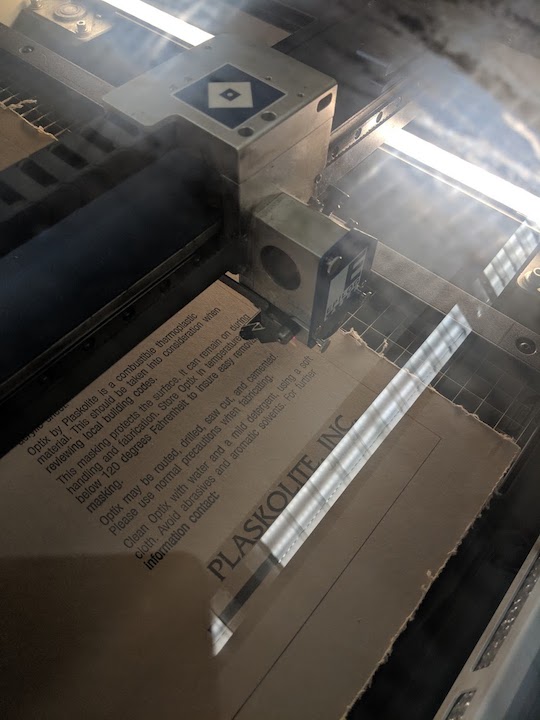
Not much to see here, the laser is cutting through the paper and the acrylic
A short video of the laser cutter in action. The paper did occasionally flare up, but it didn't seem to affect the cutting or the final product at all.
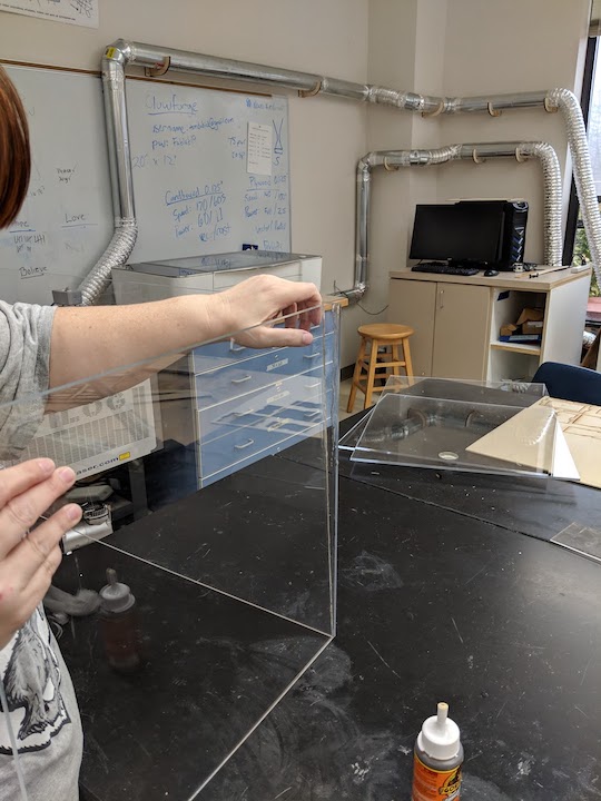
Here the walls are being glued together with an acrylic adhesive (Gorilla Glue)
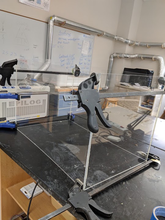
The four walls glued together, clamped and curing
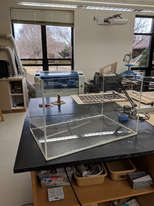
Here is the finished habitat, standing without support.
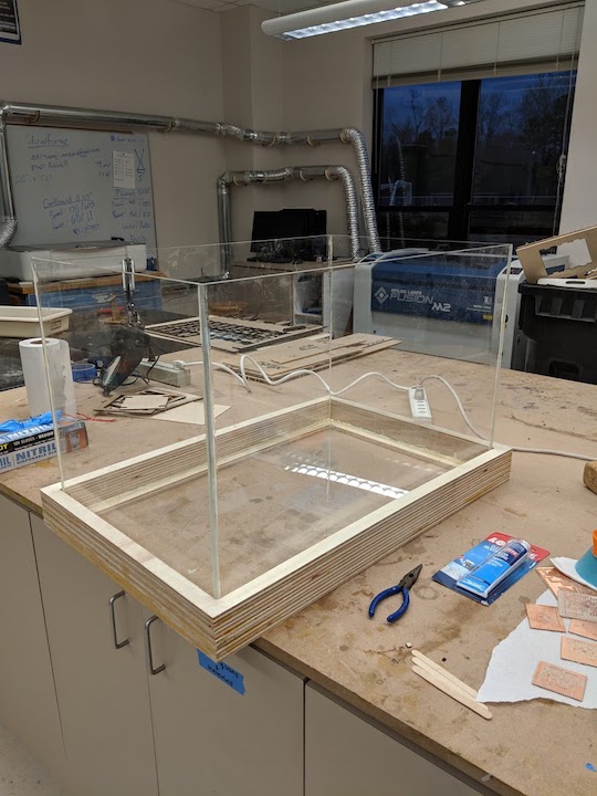
Here is the finished habitat in its wooden support base
Computer Controlled Machining - ShopBot
I began sketching out ideas for my tank. Many ideas were started and then discarded. I originally thought to have a composite base with wooden supports for the corners, but I scrapped that idea because it seemed less functional, and honestly, kind of ugly. Good design should be attractive, as well as functional! I settled on a wooden base for support for the acrylic sides and bottom of the habitat. The process for creating that can be found in Week 07 - Computer Controlled Machining. There I detail all the failures and then the final design of the base of the habitat.
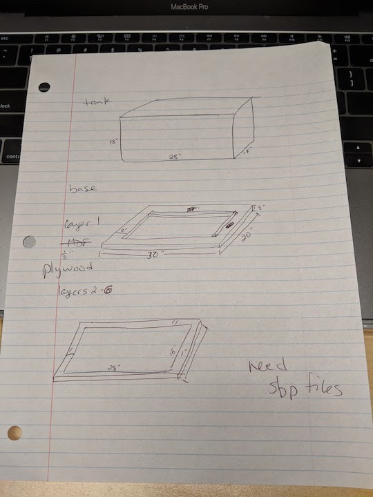
Some final sketches for the tank and wooden base
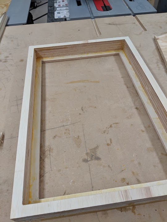
The finished wooden support base
3-D Printing
I designed and printed a bespoke food and water bowl which would be sized appropriately for the animal that the habitat was going to house. I used our Lulzbot 3-D printers as documented in Week 5. I also learned a new skill for this, because I designed the piece in TinkerCad, something I had never really worked with successfully before today. I learned how to connect and align different shapes, so I could make the bowl exactly like I wanted it. I made it shallow, so that a short-legged lizard could easily reach inside it. Many lizards are fed live mealworms and they can crawl a bit, so I also designed a slight lip on the upper edge to prevent the mealworms from crawling out.
This 3-D printed piece is to be used to make the mold for food and water bowls, for a variety of reasons. I do not think that the PLA used for 3-D printing is "food-safe" and I would not want to use it for food and water for a live animal. Additionally, it is very lightweight and could be easily overturned, creating a mess in the habitat. I plan to mold and cast this piece so that the food and water bowls are food-safe and heavier. Also, with the ability to mold more food and water bowls, if they get dirty or gross, I can simply pop out another set!
Here is my design file in .stl Food Bowl (.stl)
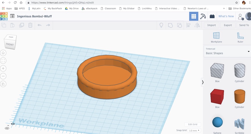
The piece being designed in TinkerCad
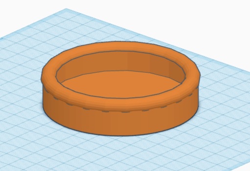
A closer view in TinkerCad, still
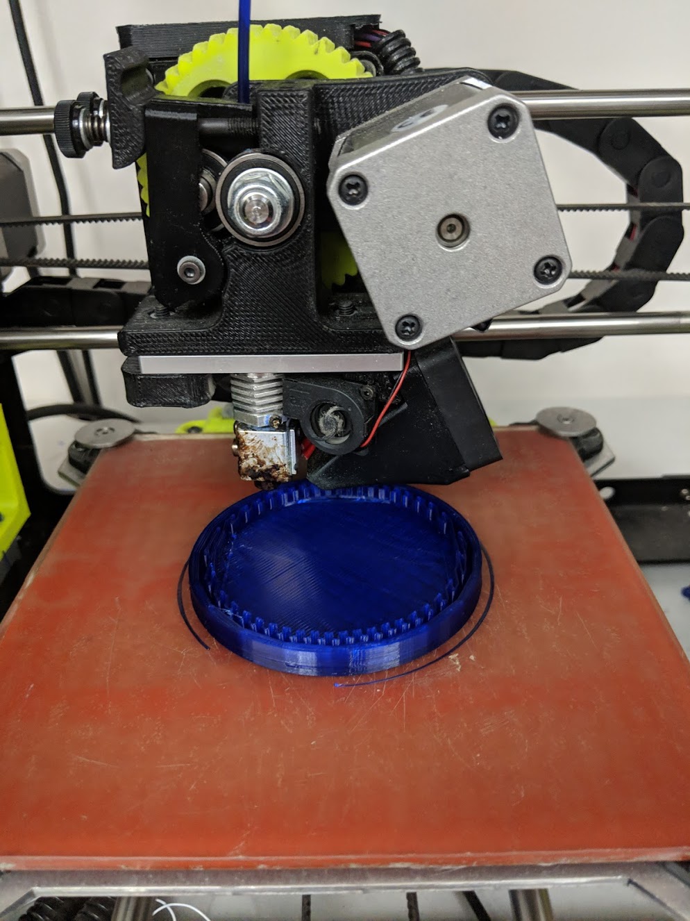
The bowl, in the process of being printed on a Lulzbot 3-D printer
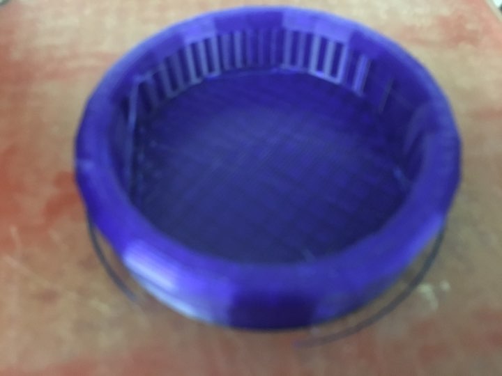
It's done! Success!
Ha! Just kidding. It's never done right on the first try. Or even the second. But if you persevere, IT WILL GET DONE. After I molded this first printed piece, I realized I would not be able to cast it, because the base was so shallow the bowls would have no bottom. So, back to the drawing board and a new bowl.
The third time was the charm, I printed a piece with a very long base so that it would allow the molding material to be deep enough.
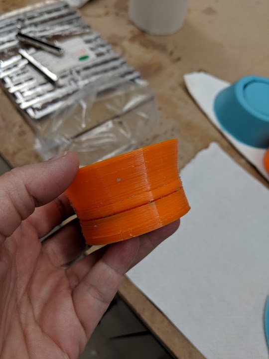
The final bowl
This final one finally worked, because I incorporated a long enough base to allow the mold to be deep enough so that the bowl would have a bottom. It really is difficult, sometimes, thinking about the positive and negative spaces.
Molding and Casting
Making the Mold
I knew that I wanted to mold and cast the food and water bowls for my animal habitat, for a variety of reasons. First and foremost, these sorts of bowls can get dirty and gross and harbor micro-organisms that can be hard to clean and dangerous to the health of the animals. Therefore, I wanted to be able to create a bowl as needed, on demand, and a mold that I could cast at will seemed the perfect use for this. I had initially thought to 3-D print the food and water bowls, but I soon realized they were too lightweight and could be tipped over, making a mess. Also, there is some debate about the food-safety of PLA/ABS plastics, so I wanted to use only materials that would be safe for the animal(s). I did some research into molding and casting materials, finally finding this FAQ from Smooth-On. It seems apparent to me that if a material is aquarium safe, it will be food and water safe for a reptile, as well. So, working from this list, I chose Mold-Star 30 as my molding material, and Smooth-Cast 326 as my casting material.
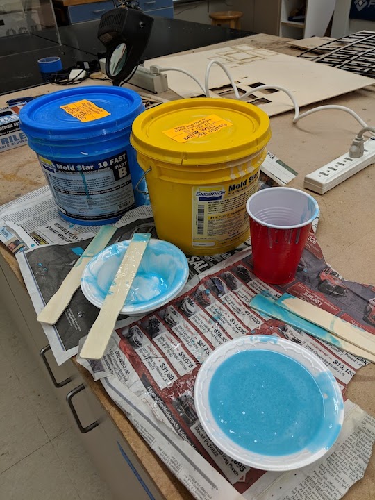
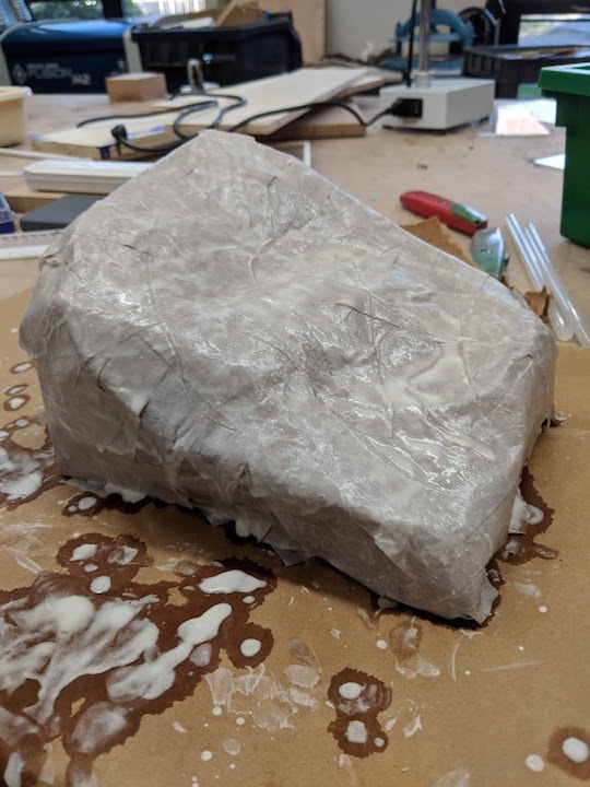
I first 3-D printed the bowl as I wanted, shallow and wide with a lip to prevent mealworms from escaping. Then I affixed the bowl to the bottom of a cardboard bucket that I could use to pour the molding material into. After that, I mixed the Mold Star A and B components very well, and combined them 1:1 by volume. That mixture also received a GOOD mixing. After that, I poured the material SLOWLY over my affixed bowl, to minimize air bubbles in the material. Mold Star has a 6 hour cure time, but I was not able to return to the lab for almost 48 hours before I demolded it.
The 3-d printed bowl glued to the bottom of the cardboard bucket
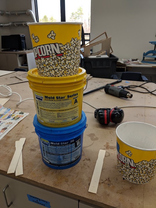
The Mold Star 30 A and B compounds and the bucket I was using for mixing
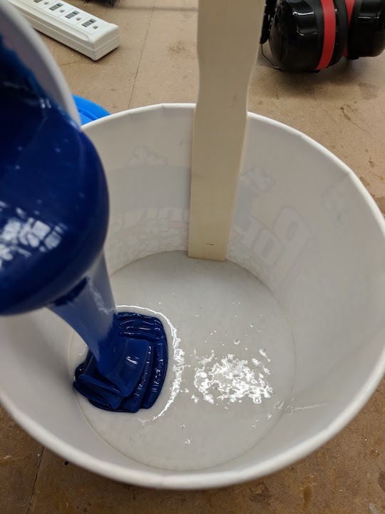
Adding compound B to compound A in a 1:1 by volume ratio
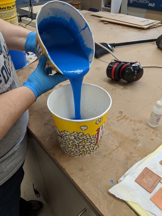
Pouring the well mixed material very slowly over my 3-d printed piece to make the mold
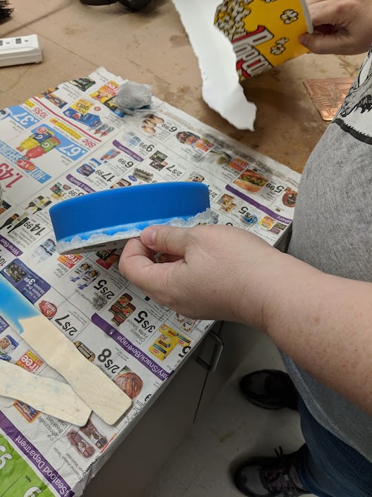
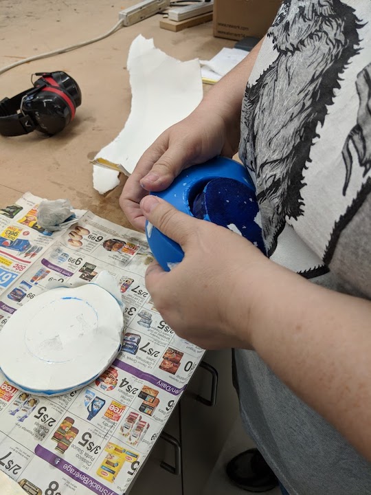
Unmolding the bowl
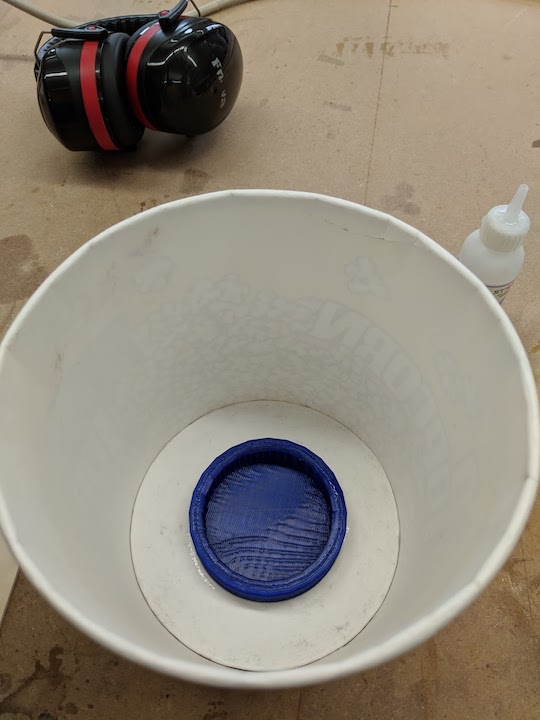
As stated above in 3-D printing, the first printed bowl wouldn't work. So, decided to remake it, and had to make a new mold. Something else I learned, the cyanoacrylate ("super glue") that I was using to hold the 3-d print in the bottom of the styrofoam bowl was apparently retarding the curing of the molding material. The edges that were in contact with the glue never cured properly. The second and third times around I used Mold-Star 16 Fast because it had a 30 minute curing time but was still aquarium safe.
The second bowl being molded. I don't have a picture of the third bowl being molded, but it looked just like this
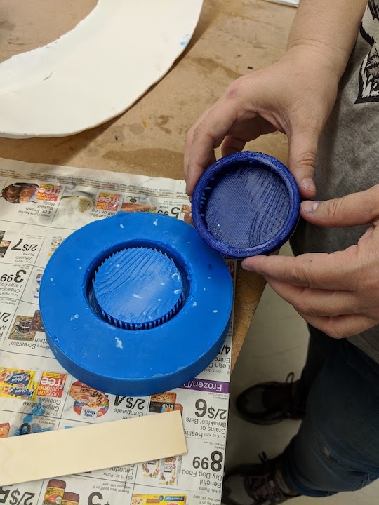
Eventually, I got all the kinks worked out between having a long enough base to make a bottom for my bowl and using double sided tape to hold the 3-d print down so that the mold material would fully cure.
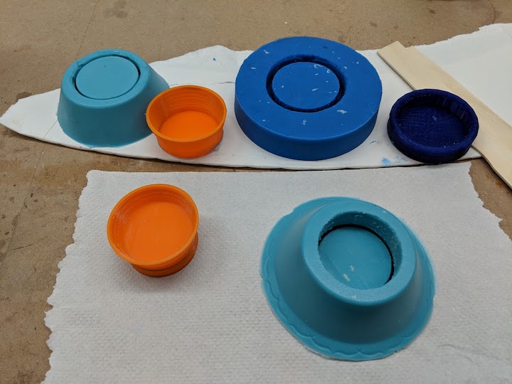
The three prints with their respective molds
Casting the Mold
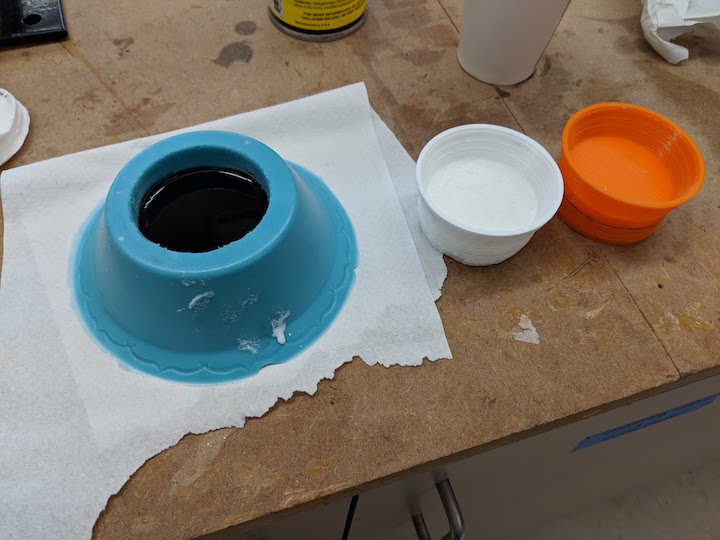
I finally had a mold I was happy with and I could start casting. Working from my list of aquarium safe materials listed above, I decided to use Smooth Cast 325 which has a pot life of 2.5 minutes and a cure time of 10 minutes. However, I didn't have enough to make multiple casts with that, so I also had to use Smooth Cast 326, which had a longer cure time of 60 minutes. I casted the 325 first and got one bowl done quickly, then unmolded it. When I was mixing up the 326, I decided to add some color, so I used the Smooth On So Strong liquid colorant. I chose black to use for the food bowl, mixed it up and cast it.
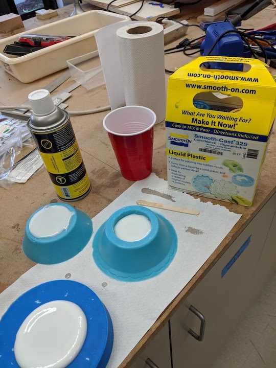
The first bowl in the process of curing. I tried the other molds, just for fun
The first bowl, next to its 3-d print, plus the second bowl being cast in black
Electronics Design
So, knowing that I had to actually DESIGN a board and not just copy one from someone else, I decided to work on modifying the oh-so-useful and helpful Sastshakit cnc board. Below is an abbreviated list of the changes I made, some pictures of the planning process, as well as screenshots of the modified schematic, board, and FabModules output.
- Changes:
- Remove pins 5-9 and ADC6 and ADC7
- The above pins were removed to make space on the board for the ambient light sensor
- This board will be purpose built for my function
- However, I left the analog pins on top because of their I2C protocal capabilities, in case I want to add more sensors
- I also left a few digital pins on the bottom
- Added ambient light sensor and resistor in space created by removing the other pins
I took my sketched out ideas and went to Eagle to modify the Satshakit board. Pictures and files are below.
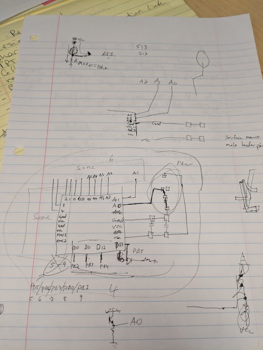
Sketching out what I want to remove and how the light sensor will fit
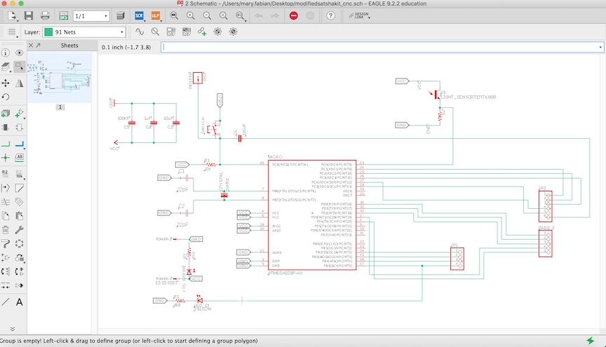
Here is the schematic in Eagle after I modified the original Satshakit
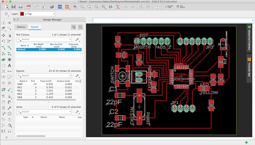
The matching board in Eagle
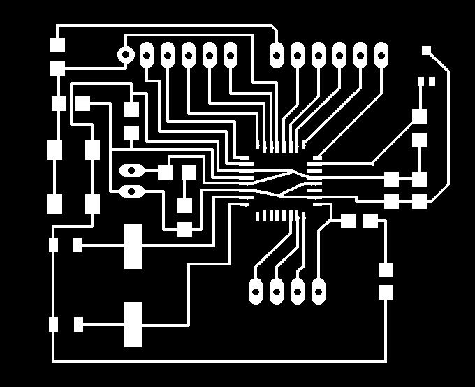
The board ready to export for milling
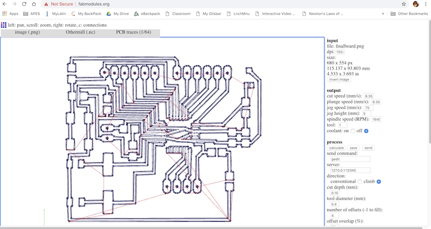
The .png after loading into FabModules and processing for the OtherMill (1/64" tool for traces, 4 offsets)

I also made an outline file to cut the board out of the material
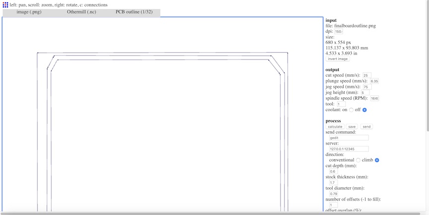
The FabModules setup for cutting out the outline (1/32" tool, 1 offset)
Download the .sch, .brd, and .nc files below
Modified Board (.sch)
Modified Board (.brd)
Modified Board Traces (.nc)
Modified Board Outline (.nc)
Electronics Production
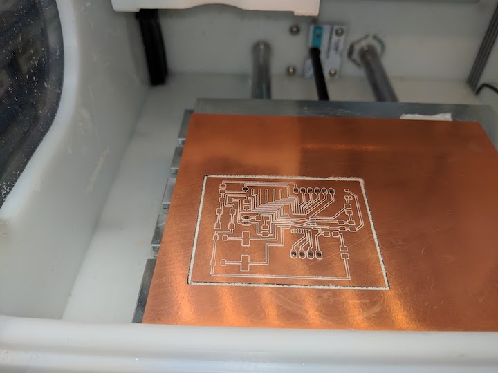
Sigh. Well, the best laid plans, so they say. I loaded up my files into the OtherMill, as I have done SEVERAL times before. It said it would take about 50 minutes, which seemed long, but whatever. I ran it, and thought it looked odd... really large on the FR-1 blank. Maybe this board was bigger for some reason? That didn't make sense, but I kept going.
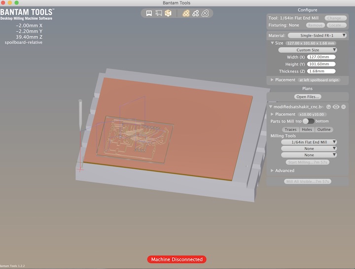
The final board file loaded into Bantam Tools, ready to be milled on the OtherMill
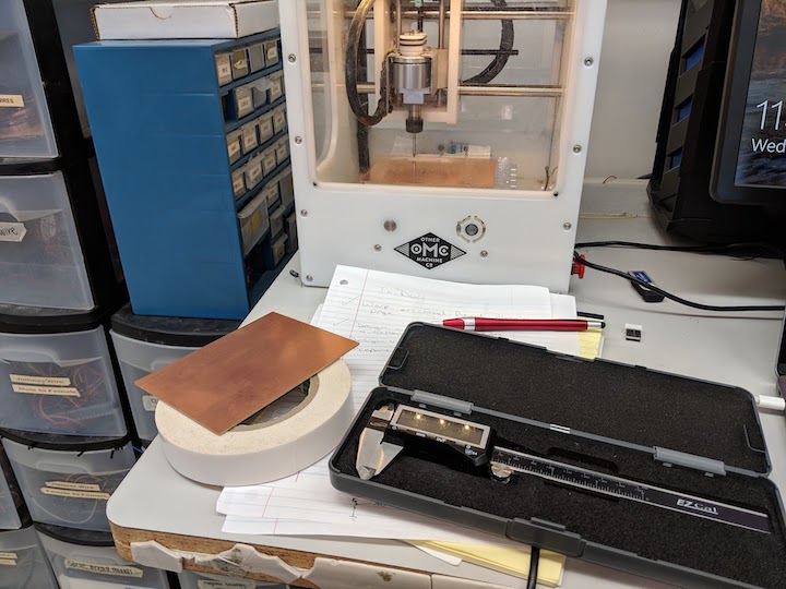
After extensive measuring and prep, milling has begun!
I soon realized that something was wrong, but I decided to let the whole thing continue. I started doing some more research while the milling was going on, eventually landing on the Bantom Tools Resource page for Double Sided Boards, as I couldn't find one for single sided. I started browsing through, congratulating myself for doing what they had suggested in terms of measuring and taping down. But then something in the step-by-step walkthrough caught my eye... "Import a double-sided PCB file. EAGLE .brd and Gerber files are both supported." I could import my Eagle .brd file?!?! I didn't have to go through all that exporting of a monochrome image, importing into FabModules, and calculating the g-code from that? I decided to try this, since when I pulled my board off the mill it looked terrible. Bits of copper were hanging off and some traces looked to be completely non-existent. So, I loaded the Eagle .brd file in and it immediately looked better. The size seemed more in keeping with what I was expecting, and the option to mill the holes and outline were there, also! I would not have to drill the pin holes?! This was so helpful and I am so glad I learned this!
Second attempt is being milled. Fingers are crossed!
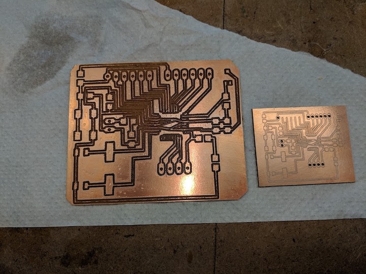
Side by side comparison of the two boards. The new one looks so professional!
I am still not sure why the g-code generated by FabModules was so far off, but I am extremely glad I learned that I can upload an Eagle .brd file into Bantam Tools for the OtherMill. That is a huge time-saver (and apparently mistake fixer). I've pulled all my parts, so on to the soldering!
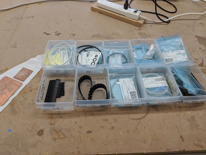
All my parts are here and ready to solder!
I was not as ready as I thought I was. (Of course). I realized, upon showing pictures of the new board to my partner that evening, if you look at the upper left part of the board, that one set of pads had not milled out. I had no idea why? They were in the schematic and on the .brd file. The next day I went in, and sure enough, when I looked at the file the pads were there, but they would NOT import into Bantam Tools. I had to delete that set of pads and add a different set (I have no idea why), but this fix seemed to work. I was nervous about the TINY space between the traces on the board, so I decided to try to use Fabmodules again, and see if I could get more spacing with offsets. Long story short, I ended up making, in total, 8(!) boards before getting one that was the right size AND had spacing I felt I could work with. I also messed up soldering on 2 boards, before I finally got one that was not shorted out somewhere!
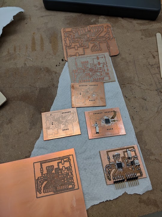
Here are the 7 failures. Some are the wrong size, some are not milled correctly, and some are not soldered correctly
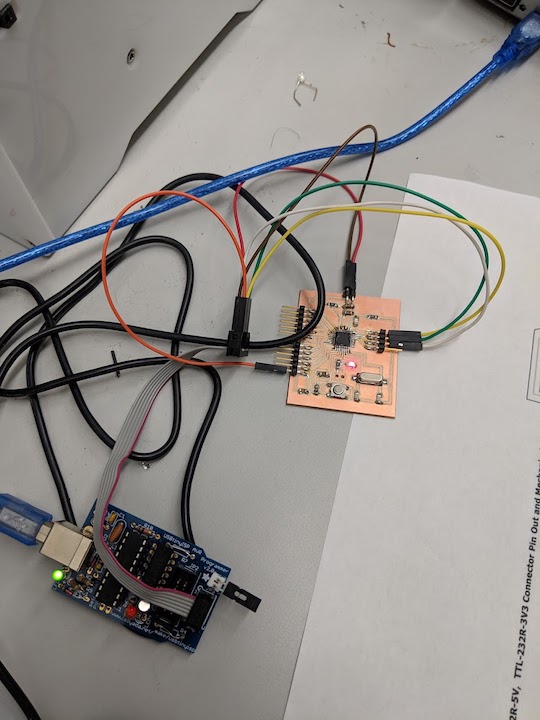
Success! Here is the board getting it's bootloader burned on
Embedded Programming
So, after a long string of frustrating failures, I finally got my board milled correctly, soldered correctly, and working. I burned the bootloader as outlined earlier. Then I modified some Arduino code to register the ambient light sensor and to turn the green LED on if the ambient light was below a certain level. To determine that level, I hooked the board up to the Arduino serial monitor and checked the numbers that represented different amounts of light. I decided that if the light value was below 100, it should register that as the cutoff and turn on the green LED.
The modified Arduino code to make the LED turn on when the light levels are low
Input Device
After I had the Arduino code compiled and uploaded as outlined above, I tested it and it worked perfectly! I took a video showing the operation. When you cover the light sensor and the ambient light level is below the cutoff threshold, the green LED turns on. When you remove the cover and the ambient light is high, the green LED turns off.
Video of the sensor working.
All in all, this was TOUGH. But I got it done and this board will work with my Final Project perfectly! I am pretty excited to be nearing the finish line.
Output Device
As I documented in Week 10 - Input Devices, I modifed the Satshakit board to have an onboard ambient light sensor, which actually measures 'illuminance', in lux. This will work in my Environmentally Responsive Animal Habitat Final Project. When the ambient light levels drop below (or go above, depending on how you program it) a certain level, a "High" signal is sent to the output pin. This can then be used to turn on a heat lamp, UV light, etc, inside the habitat. As with everything else I've been designing for this habitat, the safety of the animal is of primary concern. So, to eliminate high voltage wiring safety concerns, I chose to use the IoT Power Relay from Digital Loggers, Inc to turn the heat lamp, etc, on and off. It has four onboard outlets, two that are "off" unless told to be "on", one that is "on" unless told to be "off", and one that is always "on". It finally arrived and I set about hooking it up.
Well, like EVERYTHING else on this project, nothing works the first time, right? I realized I didn't have enough ground pins to hook up the board to the ftdi chip for power AND hook up a ground to the IoT relay. I ended up soldering some wires together to make a splitter with two male wires and a female wire.
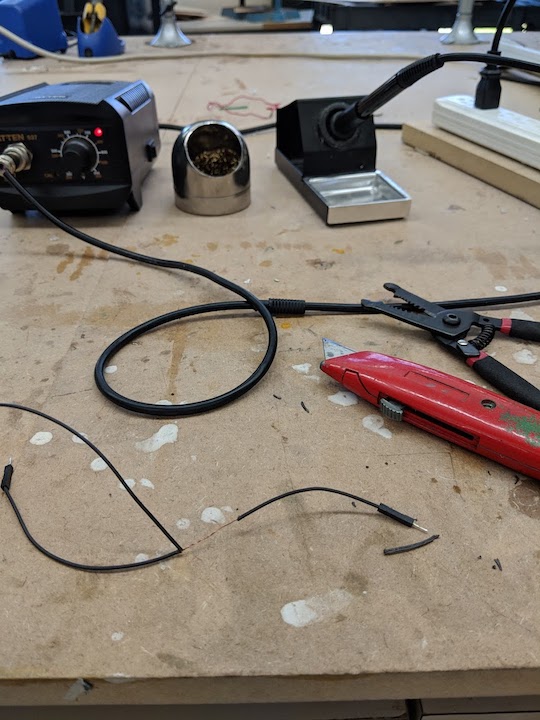
Splicing and soldering my splitter
So that ended up working pretty well. I hooked up the board to the ftdi chip for power, plugged it into the "always on" outlet on the IoT relay, and wired the output pin and ground into the IoT relay. I used a plasma ball to plug into the off-unless-on outlet so I could see if it worked.
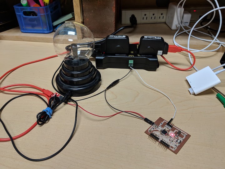
The setup with the board hooked into the ftdi chip for power, the IoT relay, and a plasma ball
IT WORKS!!! I cannot believe it, this is the last thing I had to do for my project and it works and I am so, SO excited.
The light sensor and IoT relay working together to turn the plasma ball on and off
The board in place on the habitat, when the room lights are turned off, the light in the habitat comes on
Wildcard/composite
Because a live animal is going into this habitat, I was very careful that all the materials I used to create it were non-toxic and animal safe. I knew I wanted to make a composite piece for decoration and animal enrichment. This piece would mimic a dry desert rock or basking area. I originally had thought to make the composite out of burlap and epoxy, but I was not sure of the epoxy material's ability to be used in an animal habitat. (I knew the urethane casting material was NOT considered aquarium safe, for example.) I looked into other composite materials and finally decided to use Papier-mâché, or paper mache as it's usually spelled in English. This material has been used since the Egyptian times and is a very strong and durable composite. It can be made from a variety of materials, as I learned at the Recipes Page at Ultimate Paper Mache. I chose to use the recipe with only food ingredients, simply making a paste out of flour and water. But first, I had to make the support structure, called the armature, that I would layer the composite material strips across. I made the armature out of foam, craft sticks, hot glue, and craft paper. I built it to have terraced layers for the reptile to be able to crawl up onto, but not so tall it could escape. Once the armature was finished, I mixed up the paper mache and began layering strips of newsprint material across it.
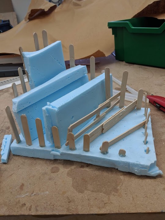
The armature, almost finished. You can see all the parts that went into making it
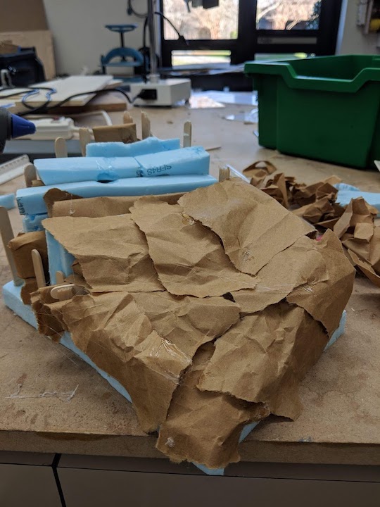
The armature, getting covered with craft paper to have a solid surface to layer the paper mache over
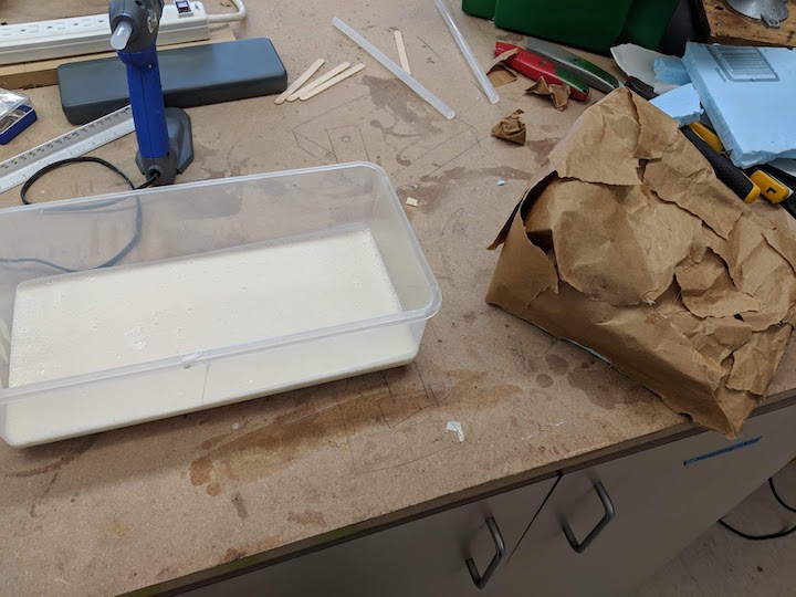
The paper mache paste and the armature
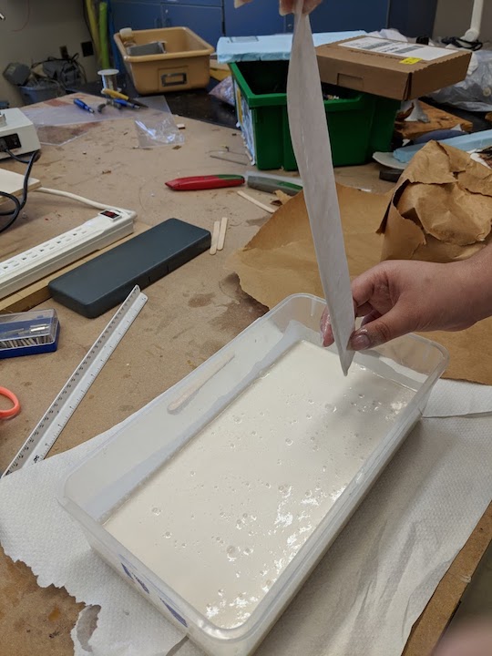
Running a strip of newsprint material through the paste. You want it wet but not dripping with paste.
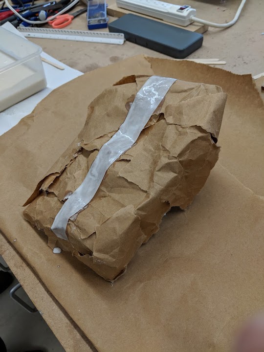
The first piece is in place!
The armature is completely covered with paper mache. It will dry hard and solid
Wildcard/Textile
Because I had some extra time and was looking for something to "dress up" the habitat, I decided to knit a lounging hammock for the reptile. I had seen these in reptile habitats before and thought they were pretty cute. I already knew how to knit, so I worked up a pattern that would make a triangular hammock that could be attached to the corner of the habitat and began.
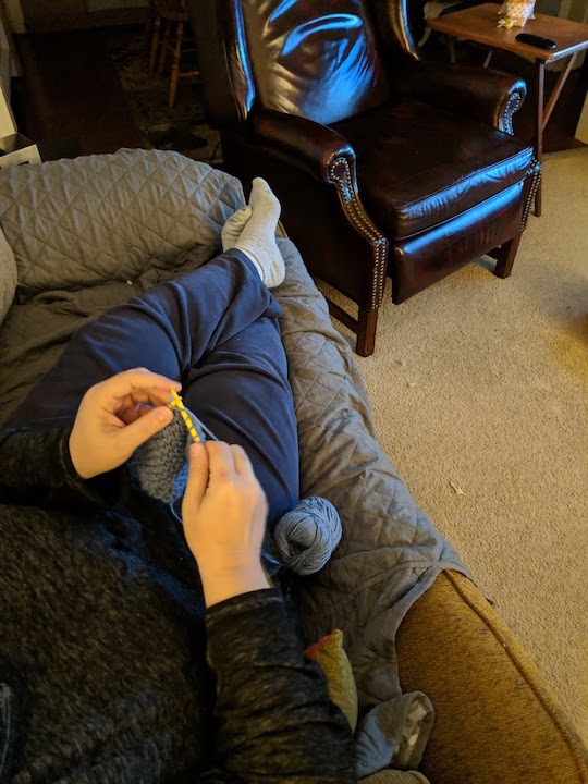
Knitting the hammock
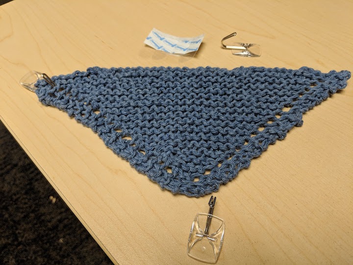
The finished hammock ready to be installed
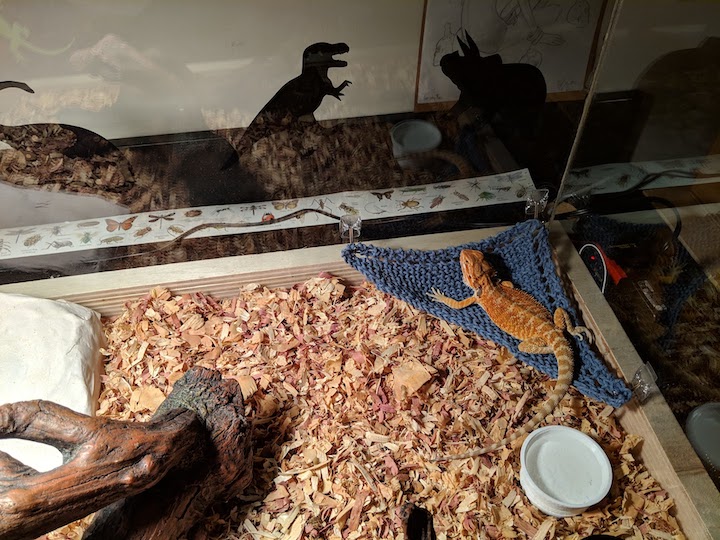
Pascal enjoying the hammock
It's Done!
And that's the end of all my planning and process notes! To see the final project go to my Final Result page. Thanks for reading!