Exercise 07 - Computer-Controlled Machining
Assignment
Group Assignment
test runout, alignment, speeds, feeds, and toolpaths for your machine
Individual Assignment
make something big :)
Group Assignment
We did various tests on our ShopBot, including checking the runout, the levelness of the sacrificial layer, and the tolerances of cuts to some test pieces. We tested the runout with an Alina Dial Test Indicator, shown below. We discovered the runout to be on the order of [XXX].
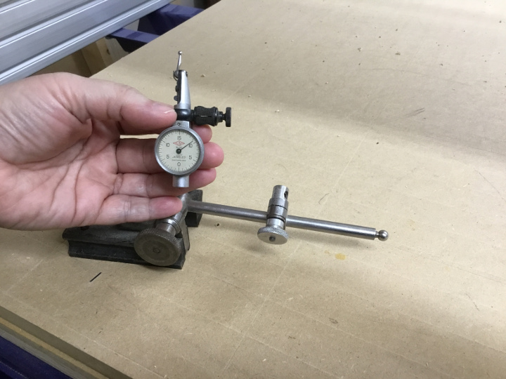
Alina Dial Test Indicator
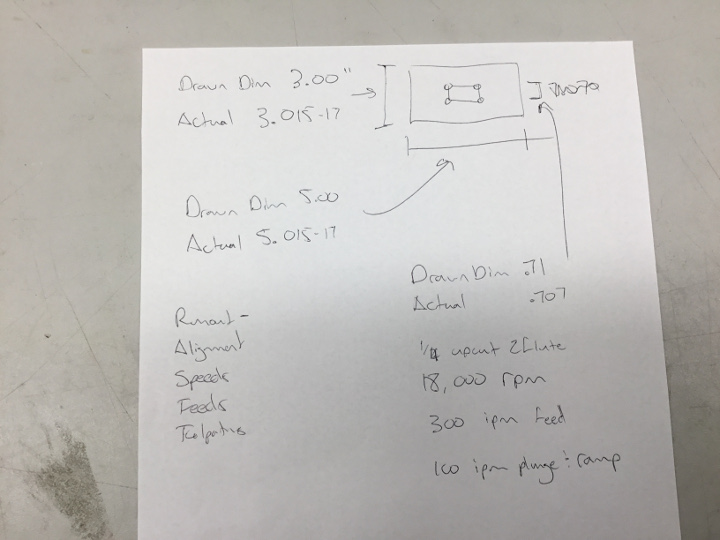
We also tested the precision tolerance on some test cuts. The test pieces were designed to be exactly 3.00" by 5.00" and it turned out to be consistently over by 0.015-0.017", actually measuring 3.015-17" by 5.015-17". The rectangular cut in the middle had a drawn dimension of 0.71" but measured an actual dimension of 0.707", which is consistent with the others, around 0.015" on either end. The test pieces were cut with a 1/4" upcut tool at 18,000 rpm and a 300 ipm feed.
- The test files we ran for the ShopBot tolerance testing can be found here.
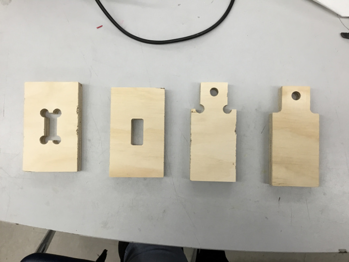
The cut test pieces
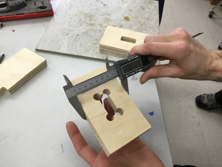
Measuring the precision of the cuts
Doing some "figuring" to measure tolerances
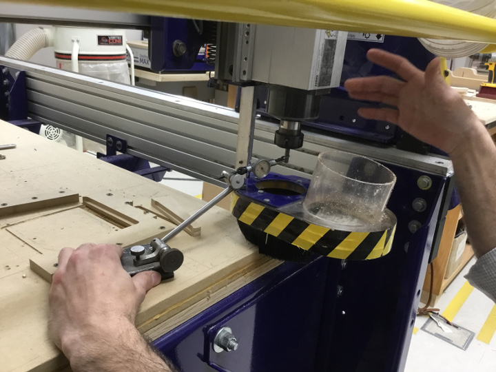
ShopBot runout testing
Individual Assignment - Part 1
Design
I love the idea of making a piece of furniture. Neil said this week's assignment was his favorite and I agree. I have made some furniture in the past with table saws, radial arm saws, etc. I have renovated my kitchen and built pens and containments for my goats (which never worked). I was really excited to try to make something on the ShopBot we have in our Lab, as opposed to the tedious measuring (twice but cutting once) and laying out of the wood in a more traditional carpentry setting. I didn't really know where to begin, though, so I started with some online research. I googled 'Shopbot projects' and looked at pictures. I found several designs that appealed to me and had a lot of ideas. (I also called family members to see if they had a "need" for any furniture pieces, which might help me decide what direction to go, but the consensus was "no, thanks".) I finally decided I was going to make a bench, similar to the tutorial found here at ShopBot Projects.
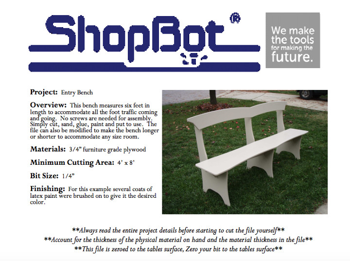
Image from ShopBot Project page
The zipped files for the bench were included from the ShopBot Projects page. I have linked the unzipped files below.
I had never used the ShopBot, or Vcarve, before, so I poked around a bit before just loading my files into the ShopBot and going. I opened VCarve and played around with drawing things and using the menus and generating toolpaths. I took the .sbp files I had from the ShopBot Projects page and generated new toolpaths, just to make sure I could do it.
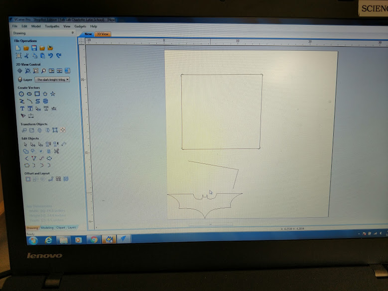
Practicing drawing shapes on VCarve
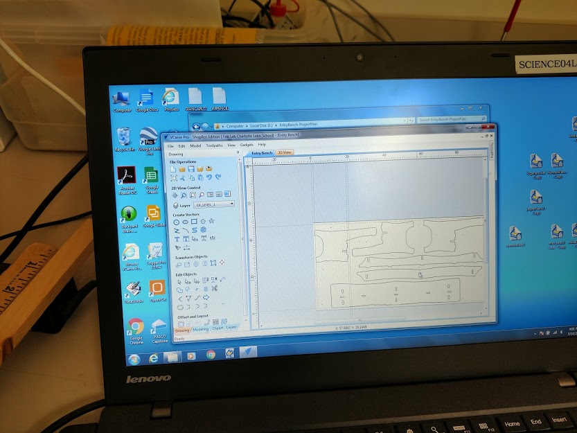
The pieces for the bench laid out on VCarve, ready to cut
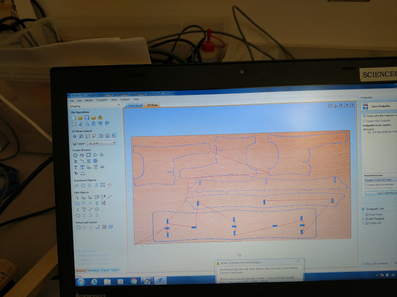
The toolpaths generated and ready to go!
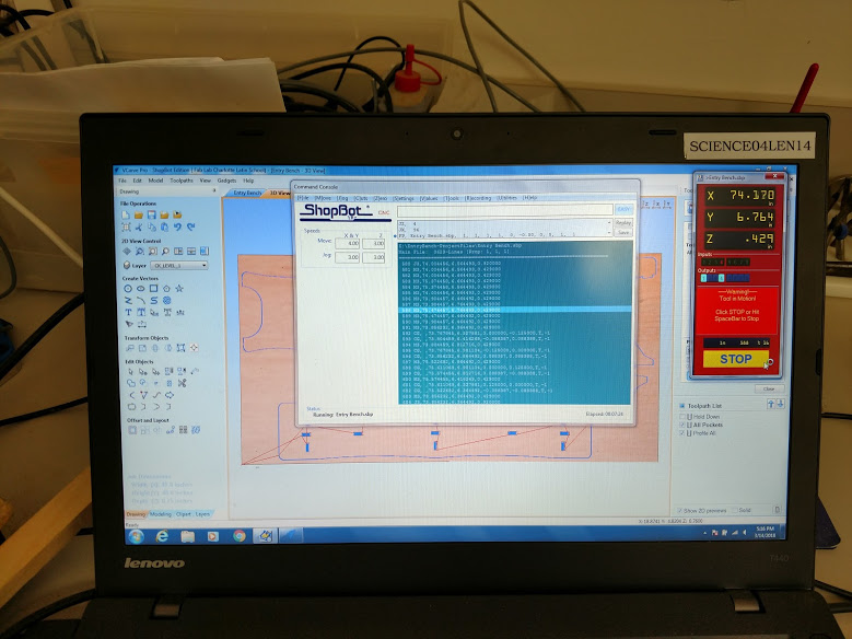
The gcode in ShopBot
Implementation
At this point, it was time to send the files to the ShopBot and make the magic happen. It was louder than I thought it would be, which initially made me nervous because I remembered what Neil said about listening to the ShopBot and gauging how it was going based on the sound. It made sense after a while, though, as it started cutting and I could distinguish the different sounds the machine made when cutting, moving, etc.
Several of the pieces have been cut. It goes faster than I thought it would
Video of the ShopBot cutting out the bench
A small mistake, explained below.
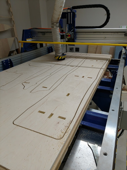
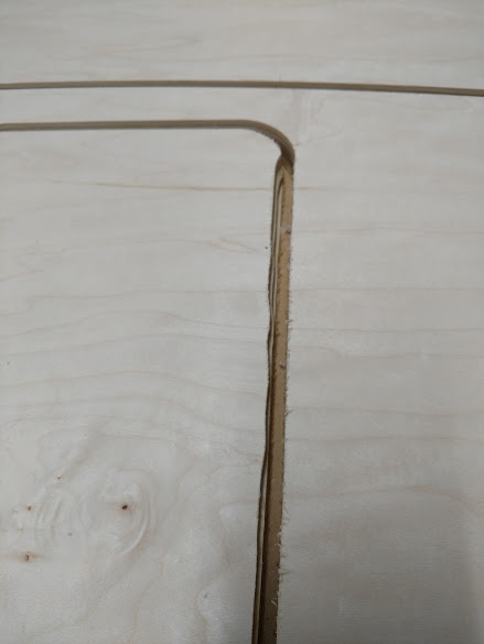
I did make one major mistake when cutting out the bench with the ShopBot, which I won't make again. The design came with a toolpath to cut holes for suggested "Hold Down" screws. I dcided to omit this step as I assumed just screwing the material around the edges would be enough. (It was not.) The pieces "wobbled" and moved during cutting and created wave-like patterns in sections that should have been perfectly straight. If I had screwed in the hold down screws where suggested, I think it would have taken care of the problem. Listen to the experts, I suppose! Below I have the completely cut pieces, ready to be broken out of their tabs and assembled.
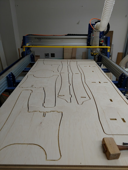
The completed pieces on the ShopBot
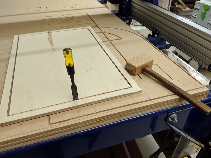
To make the pieces look more finished, I decided to route the edges before assembling the bench. I had never used a router before, but after a few minutes of training I was off and running. I really like the way the routed edges make the piece look more polished. After routing, and lots of sanding, I assembled the pieces. I did use glue to assemble it because I knew I was going to put it in the hallway at school and allow students to sit on it.
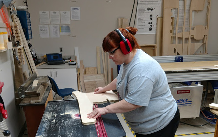
Routing the edges of the pieces
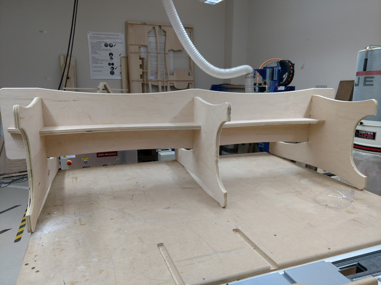
The parts assembled (waiting for the glue to dry)
Product 1
I did have one problem in the implementation of the bench, related again to not following the suggestions for where to place the hold down screws. Instead of making a slot in the back that the support pieces fit in, the ShopBot cut all the way through the material, making a hole that was visible from the front. My supposition is that the material bowed up from only being screwed on the edges, which made it higher in the middle and get punched through.
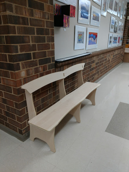
The completed bench

It's sturdy!
All in all, I really liked making this, and I have already thought about how I could do it better next time. I really like the ShopBot and am planning on making some other pieces soon.
Individual Assignment - Part 2
Design
After working on the bench, I felt more comfortable with the ShopBot. However, in the ensuing months that passed since I last did this, I forgot a couple things AND several things in our Lab had changed. Following is the documentation for the piece I made for my Final Project on the ShopBot.
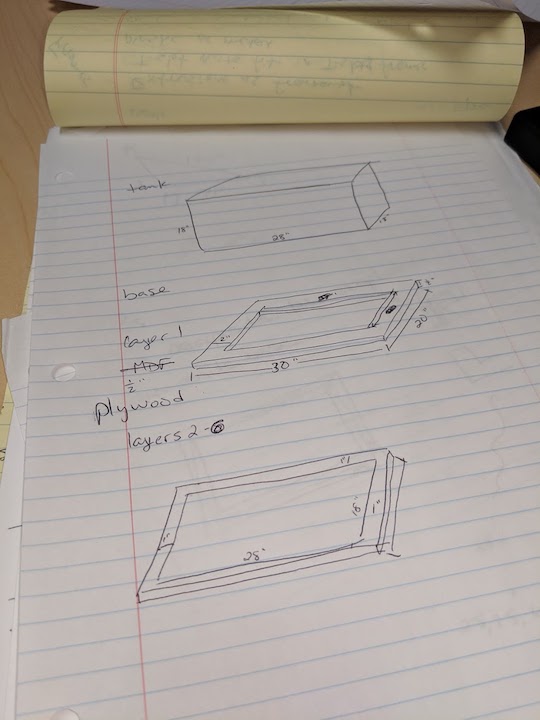
I had one failed design that I am going to document here. My final design for my Final Project is documented below this one. I am making an animal(reptile) habitat for my Final Project. I am cutting the acrylic sides on the laser cutter and gluing them together with an acrylic epoxy. However, I didn't feel like this was going to be sturdy enough, especially, laterally, so I wanted to design a base that would provide lateral support for the acrylic walls, AND support for the acrylic base. At first I had thought I would make a composite base that I would slot some corner supports into, but I realized that was not going to be as good looking as I wanted this to be, and also, not as strong as a wood base. But I didn't realize this until AFTER this first failed attempt. Of course. A really rough sketch of the sides and some planning I did are pictured below.
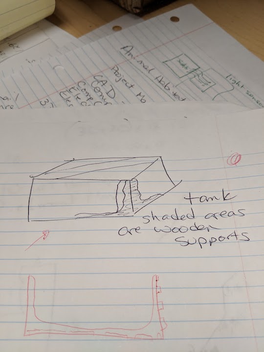
The rough design of how the sides would fit together around the acrylic edge
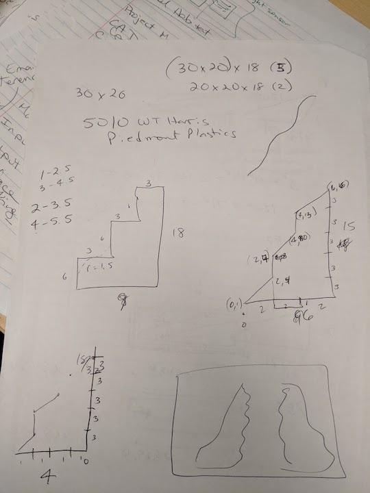
Roughly planning out before drawing it in Fusion360.
I used Fusion360 again for the CAD and CAM. I went with a simple 2-D cut for this and dog-legged the scrap edges so the tabs would be nice and square.
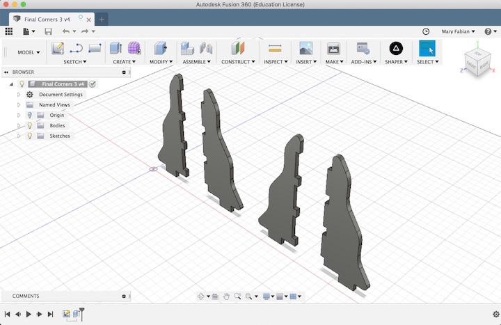
The design in Fusion
Download the Fusion360 .f3d file here.
I cut the pieces out on the ShopBot with a 1/4" flat end tool and the cut turned out quite nice. But as I said, these didn't really fit what I needed, so I ended up scrapping this whole idea.
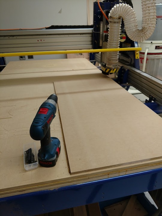
Setting up
The ShopBot in action
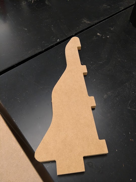
One piece before combining it with another to make a corner
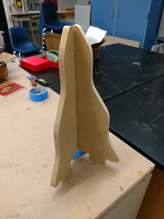
The corner assembled and standing on its own
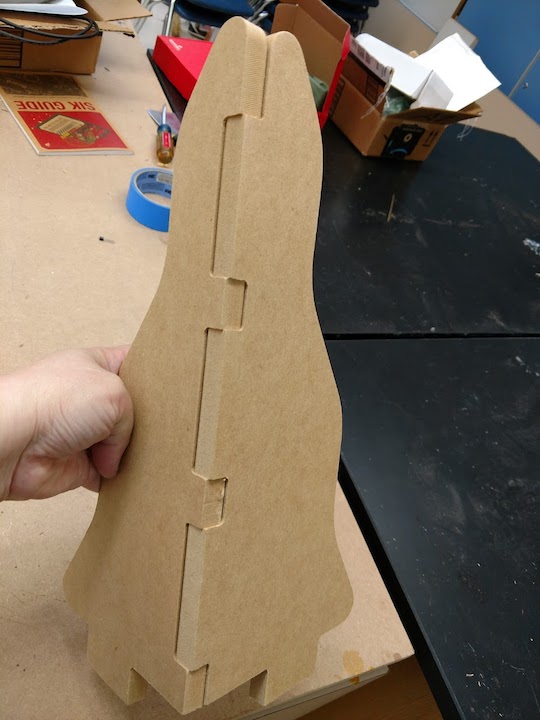
The back side
A video of me shaking it, etc, to show it's sturdy and to see all the connections.
As stated above, I originally had thought to make the base in a composite, but soon realized this would not be adequate. A solid wood base would be a perfect piece to ShopBot. I used Fusion360 to design the base pieces. Below you will find some of the planning I did for the piece, and the Fusion360 file for downloading.
Download (.svg) File here.
After designing the base layers in Fusion, I wanted to work on them on the new software our Lab had, Aspire, by Vectric. Aspire is a lot more user friendly and allows you to figure out roughing and finishing toolpaths quite easily. However, I quickly realized that I could not easily download an .svg file from Fusion360. A quick Google search led me to the Shaper Utility add in for Fusion. Once that was added to Fusion, I was quickly able to export an .svg file and open it in Aspire. I had to set up the job in Aspire, which you do on the left. You pick your material size, thickness, where your Z reference is, etc. I originally picked the machine bed, because that was the default, and had to go back and reprocess everything to the material surface when I was actually cutting (because I realized I was wrong).
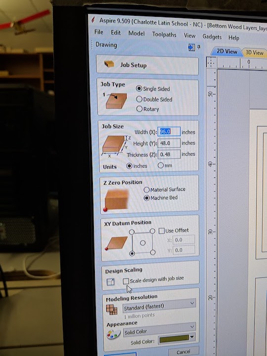
Setting up the job in Aspire
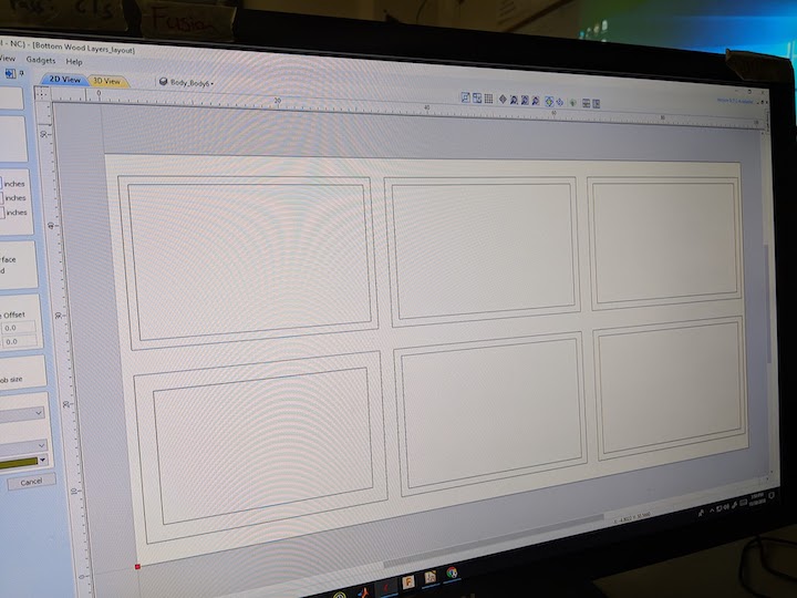
The job laid out to fit on one sheet of plywood
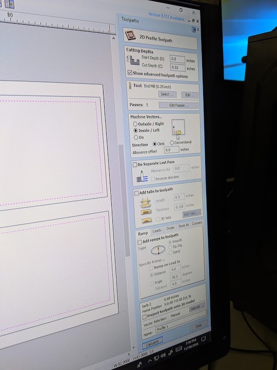
Choosing the correct feeds and speeds for 1/2" plywood
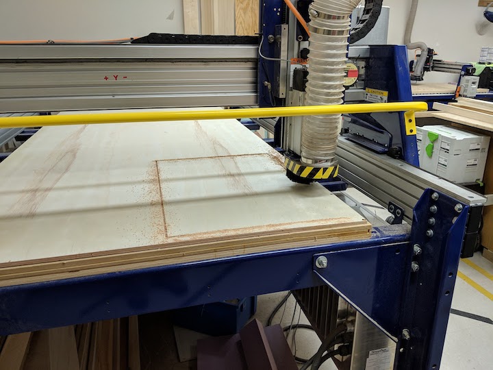
The first cut is always the most nerve wracking. Did I set it up correctly??
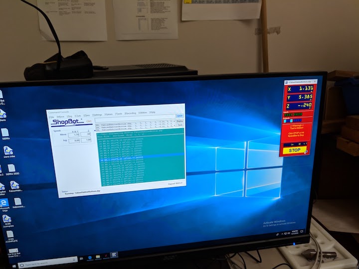
The ShopBot executing the gcode. I always find it fascinating that a string of numbers can have such meaning to a machine
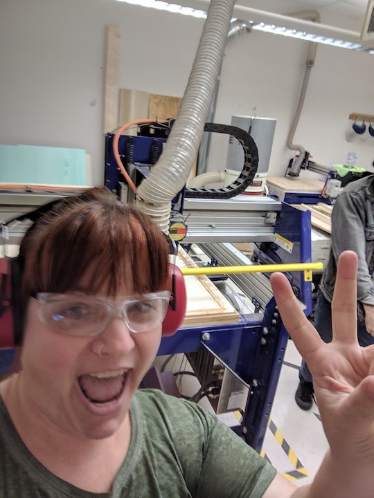
A ShopBot selfie (demonstrating proper personal protective equipment)
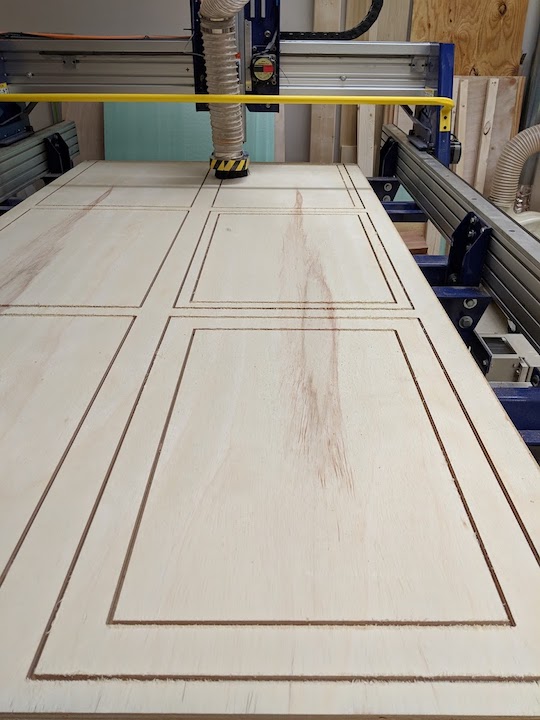
Almost done!
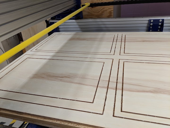
The finished piece - the square corners are awesome!
Removing the tabs to free the pieces
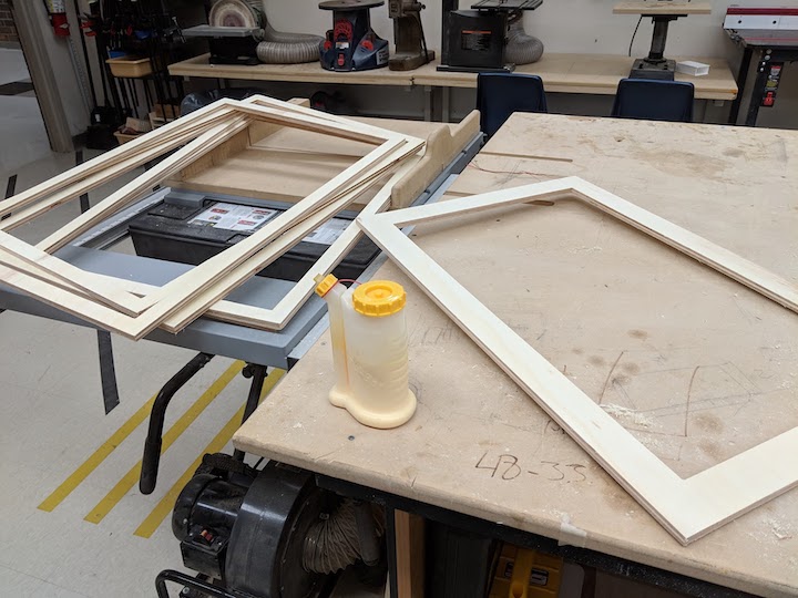
It took a bit of sanding, but here are the pieces, ready to glue
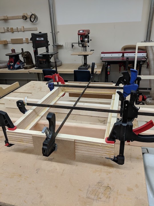
After the glue, all clamped up and ready to dry
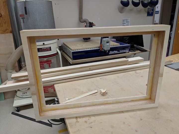
The finished base
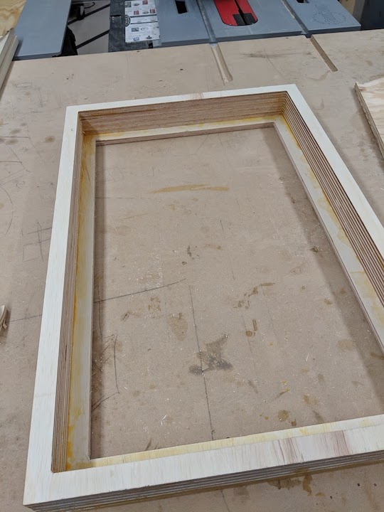
Another view of the finished base
Overall, I know this piece is not very sophisticated, but it's actually a necessary structural piece for my final project. It also helped me remember how to use the ShopBot and actually get a lot more comfortable. Before I had to ask for help, but I was able to execute this by myself. Additionally, I was able to troubleshoot my problem when I saw the first "cut" in the air above the wood, I realized I had set my Z reference incorrectly. I was able to go back in, change my job settings and reprocess each job (I had set the inner and outer cuts to be different jobs). I really really like the ability in Aspire to tell it to square off the corners without having to do the "dog bone" cuts that I had done in the past. I always thought those looked terrible.