

Week 8
Computer control machining
Group Assignment
Test runout, alignment, speeds, feeds, and tool path for your machine
Individual Assignment
make something big
Checklist
1 Explained how you made your files for machining (2D or 3D)
2 Shown how you made something BIG (setting up the machine,
using fixings, testing joints, adjusting feeds and speeds, depth
of cut etc)
3 Described problems and how you fixed them
4 Included your design files and ‘hero shot’ photos of final object
Learning from this week
1 Operating shop-bot cnc
2 Making tool path for cnc
3 Designing furniture of 1:1 scale and assemble it
Speed and Feed
Chip load: ~ 0.001-0.010" = feed rate (inches per minute) /
(RPM x number of flutes)
Cut depth: ~ tool diameter
Step-over: ~ tool diameter/2
About this Week
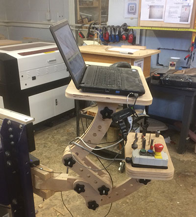
This week we need to make something big so i decided to make laptop stand for our lab Shopbot CNC machine , As it will help all CNC users in lab to operate machine comfortably for this i started looking for some reference on Internet , i found some project which i took as a reference for designing my own design and I did 3d cnc work in week 10 .
Group Assignment
My contribution in Group Work is to do 3d CNC and Do documentation of this week group work Group Work Link
Referance 2 - Description
i used this reference for making cnc laptop table , i want to do some modification in this as per my requirement
changes i want to do in this
1 this model have 7 degree of freedom as it is difficult to make it stable at perticular orientation by fixing 6 frictional joints
2 it have many linkages i want to make it simple by reducing linkages to 2-3
3 it have separate stand / table top for power control remote and laptop ,i want single stand for this
Steps for Designing the Model
As i am starting from zero so the steps i took for designing cnc laptop stand
1 Designing cad model and do assembly check
2 Design mockup from cardboard
3 Make 2d drawinng for cnc
4 Making cuttiig tool path for cutting
5 Operating machine and do cnc cutting
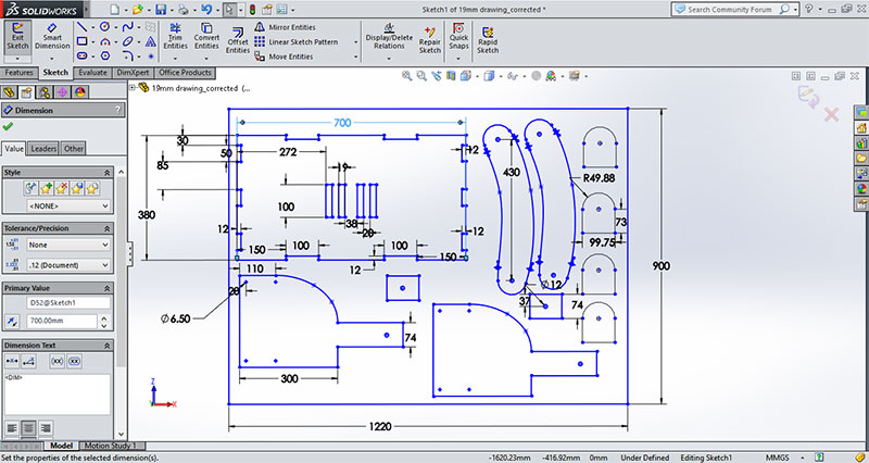
Cad Model for Mockup

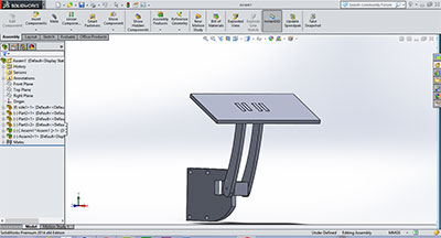
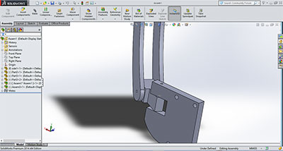
This cad model is made in solid-works and i did this by making different parts and doing assembly of them this is i just made for visualization and checking dimensional relation
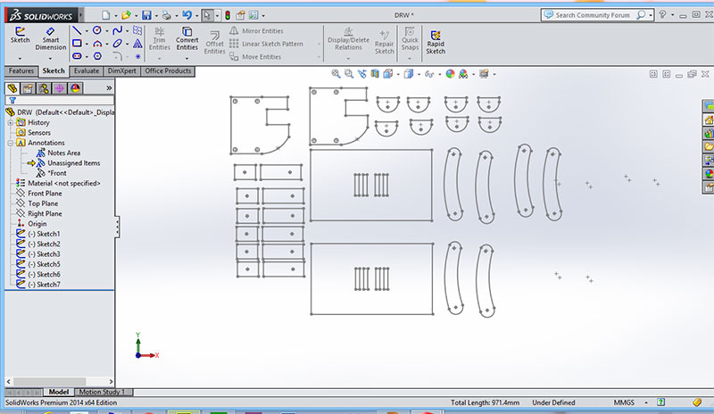
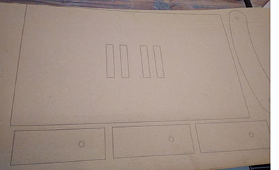
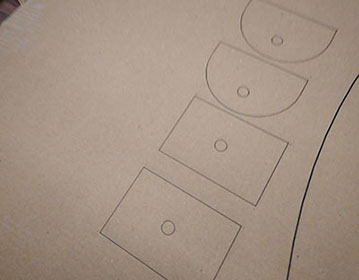
2D Design of for laser cutting
Cardboard Mockup
I did cardboard mockup of above cad model in which i cut cardboard using laser cutting machine ,the cad design for mockup i made in solidworks by taking 2d sketch of all assembled part
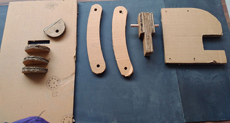
Assembly of laser cutting files
After cutting from laser i join this cardboard sheets as per my desired thickness
Video of testing Mockup
Designing Final Model
Changes done in Mock-up Design
1 i changed the height of model as earlier on testing mock i find arm length is short so i increased this
2 i removed one rotational joint along the hing ( the joint which give rotation about hing point ) as later i find there is no need of this joint in design also it may week hing point support
for more see both video of mockup and final to compare model working
CNC of final model
For cutting in cnc i used Partworks 2d for toolpath generation as we have this software installed in lab's laptop i also used this earlier for other cnc work , there are other software also as v curve and fusion 360 which you can try
Creating toolpath for cnc in 2d partworks
Step 1 Open Partworks and click on create new file
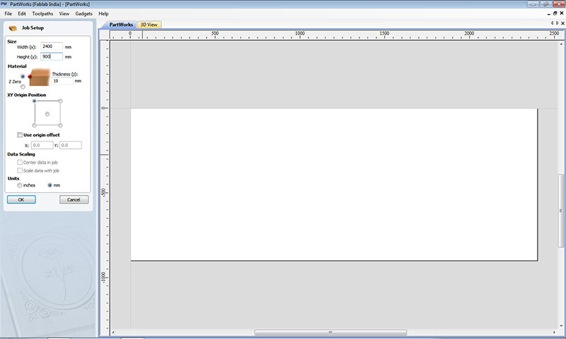
Step 2 Set the size of your sheet as my sheet is of 2400*900 so i put this dimension in that and set material z zero at at top and material thickness of 19mm
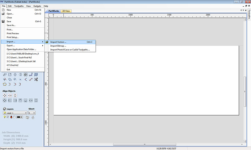
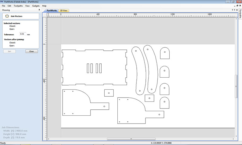
Step 3 Go to file option and click on import and import vector from here i.e dxf file which you made for cnc
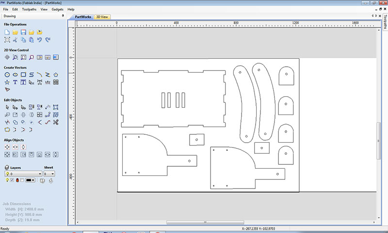
Step 4 Now join all the open vector using join command in last row and first column of edit option so it make close boundary of your vectors.
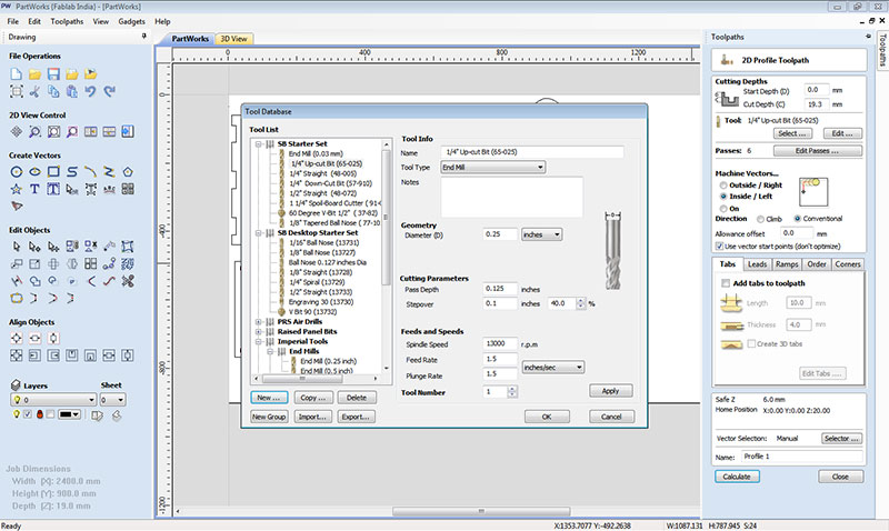
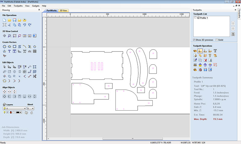
Step 5 select inner profile of drawing and go to toolpath and select create profile toolpath on this the setting i keep for tool and cut depth to 19.3mm, i want to run my tool inside the boundary as Shown.
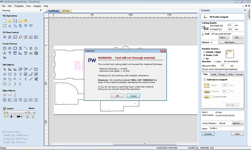
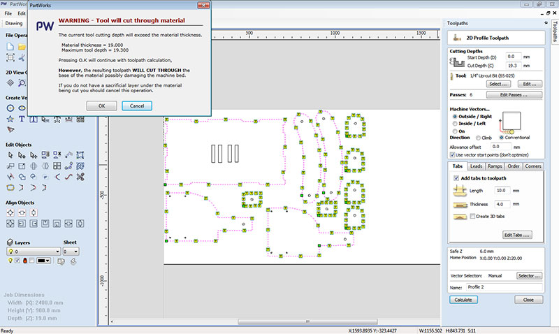
Step 6 once you select the tool and keep all parameters and click on calculate to make toolpath for the file it is showing you warning that cut depth is 19.3mm and material thickness is 19 mm
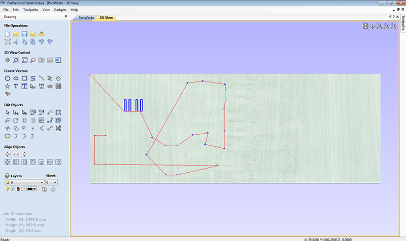
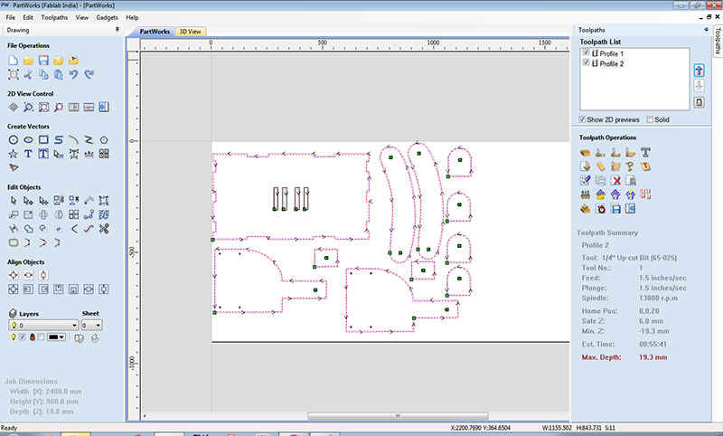
Now you can check the toolpath in 3d view on clicking on top to 3d view it shows you tool movement
Step 7 Create outer profile toolpath , once the toolpath is created now go to toolpath option and unclick the profile option and select the outer boundary profile and click on create toolpath option
Step 8 select the tool and add tabs in outer profile as tabs are joints which keep your cutting parts joint with your sheet so while cutting your tool will not move other parts ( here i select length of 10 mm and 4mm thickness)
Step 9 Now calculate the toolpath again and select both the toolpath it will show you total time it take for cutting as here it is showing here 55 minute for total cutting time and click on save toolpath option at right side
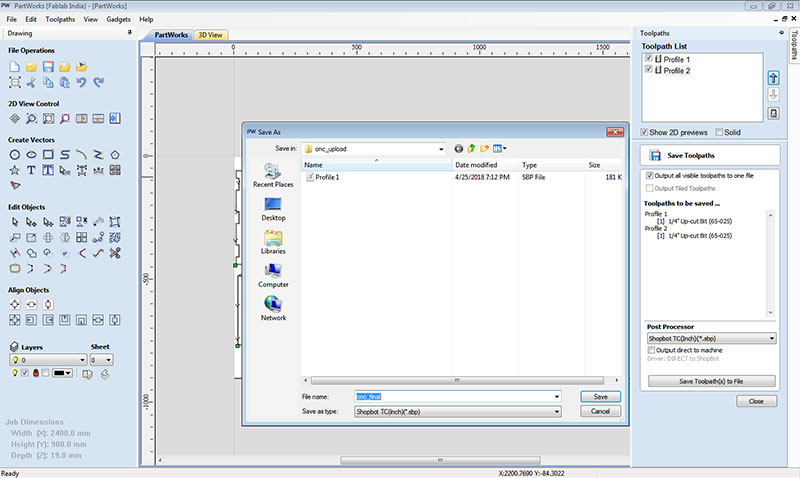
Now save toolpath to file it will save your file in .sbp format this file is gcode that is machine code for cnc cutting we load this in partworks for cutting
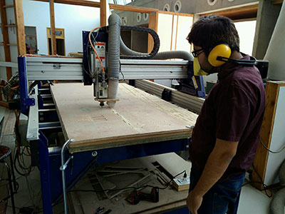
Machine Handling
On machine switch and connect cables and set laptop and mount the tool on tool head

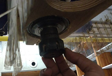
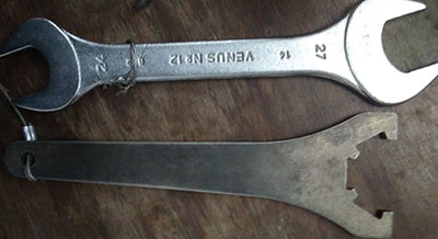
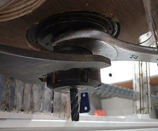
Set sheet on bed and mount the tool and and set the tool in the collet and fix the collat on the tool head
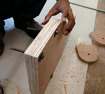
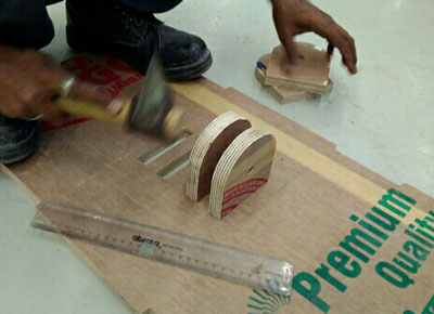
Tabs in cutting path

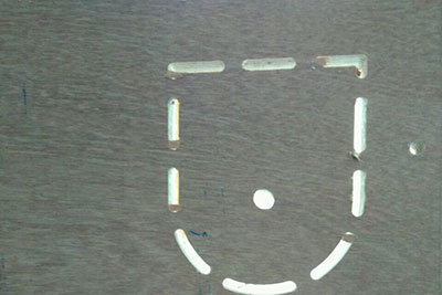
This image i taken from top
This image taken from bottom when i removed the sheet from bed
Operation on Shopbot
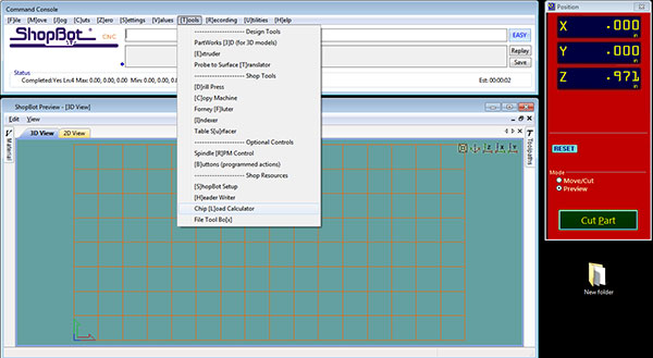
Chip Load Calculation
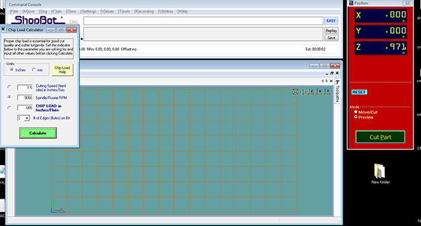
For chip load calculation i used the chip load calculator which is in shopbot software as we all use this software for operation machine , on this go to tools option and click on tools and chip load calculator , here is another link for chip load calculator shared by global evaluator
Here enter values of cutting feed rate , chip load and number of flute it will give you rpm or you can find out any parameter on giving value of rest 3 parameters
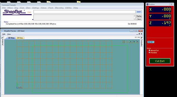
this is start window of shopbot after running spindle warm up (from c5 commond in setting ) you need to set origin ( for this go to move setting and set origin )and load file from cut Part
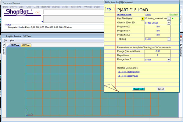
When you load file this window will pop up , now press entre and it will ask if spindle is on or not press start button on remote to on spindle and start cutting process
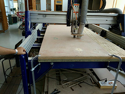
Doing Assembly of CNC Cutted Parts
As i perfect sizes of pieces so they get fixed easily on table top on fixing everything i mount the table on side of cnc and it is fixed perfectely over side of cnc i take help of mr bhavani singh technician in our workshop in fitting this to shopbot
Final Model Video
This video shows how you can adjust to move your laptop from position to another
This will show how to lock this at one position
Areas of Improvement
For anyone who wants to fabricate this design should consider the areas of improvement what i find in my design
1 In my design i have given side cuts for fixing boundary rib you can fix that for safty of your laptop
2 the bottom part which is fixed to cnc is not so strong along the bar you can increase its thickness, in my design this is of 40mm you can increase it to 60 mm as there is very little vibration due to this.
3 The rotating screw which i use inside the plywood for adjusting its movement is not holding the ribs so strongly or it may damage the internal surface on long use for avoiding this use a Al pipe in Centre of screw which will be in contact with wood and tight the knob in side for better holding.
else i find everything good about what i made in terms of design , egromnomics and strength

This work by Gaurav wadhwa is licensed under a Creative Commons Attribution-NonCommercial 4.0 International License.