Week 17 - Wildcard Week
For wildcard week, I’m testing different approaches, including composites, for making my final project casing.
Setting a brief
The assignment this week is to: “design and produce something with a digital fabrication process (incorporating computer-aided design and manufacturing) not covered in another assignment, documenting the requirements that your assignment meets, and including everything necessary to reproduce it.”
I want to use this week to make progress on my final project, and in particular the project casing. For a project with a strong aesthetic element, this is an important part, and I don’t want to fall back to common makerspace approaches such as finger-jointed laser-cut ply boxes, or a 3D printed plastic case.
The tests I’m running are:
- Can I use composites to make either the main box, or just the side panels
- Can I use folded metal to make the main part of the casing
- Can I cut and score aluminium for a casing using the milling machine we have in the lab
Cardboard prototype
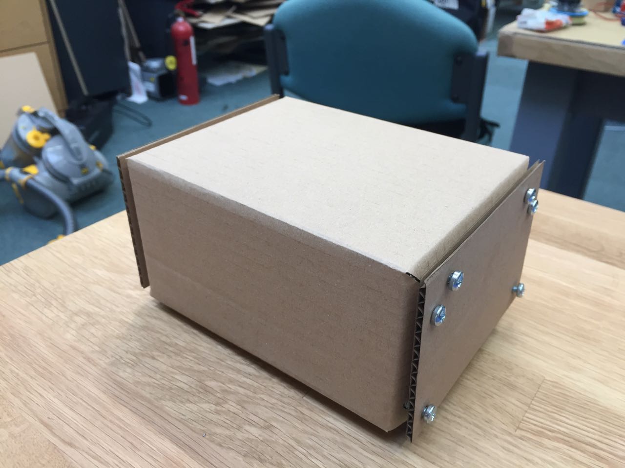
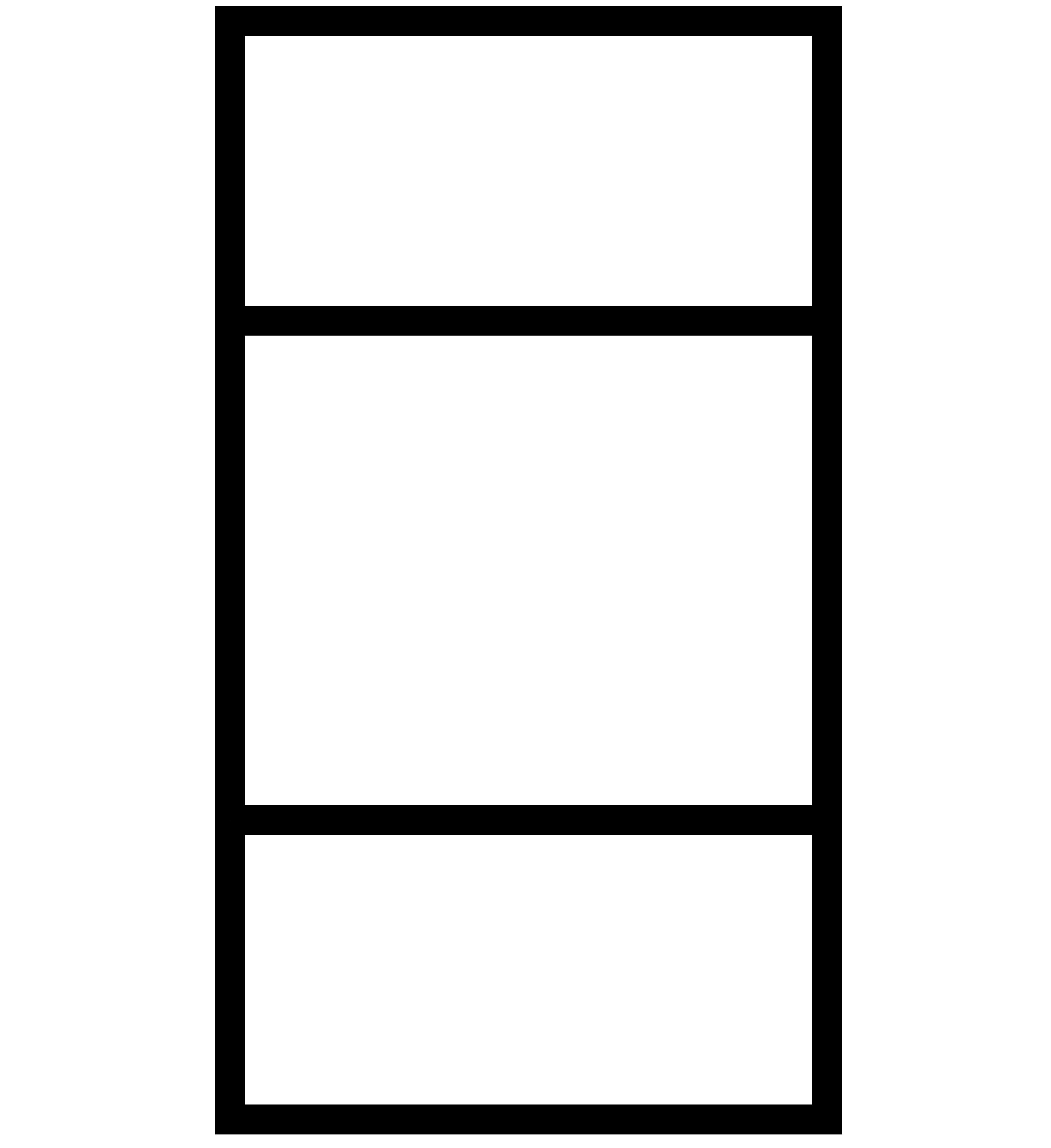
I started by making a simple card prototype to get a sense of the overall shape, size and assembly of my basic casing idea.
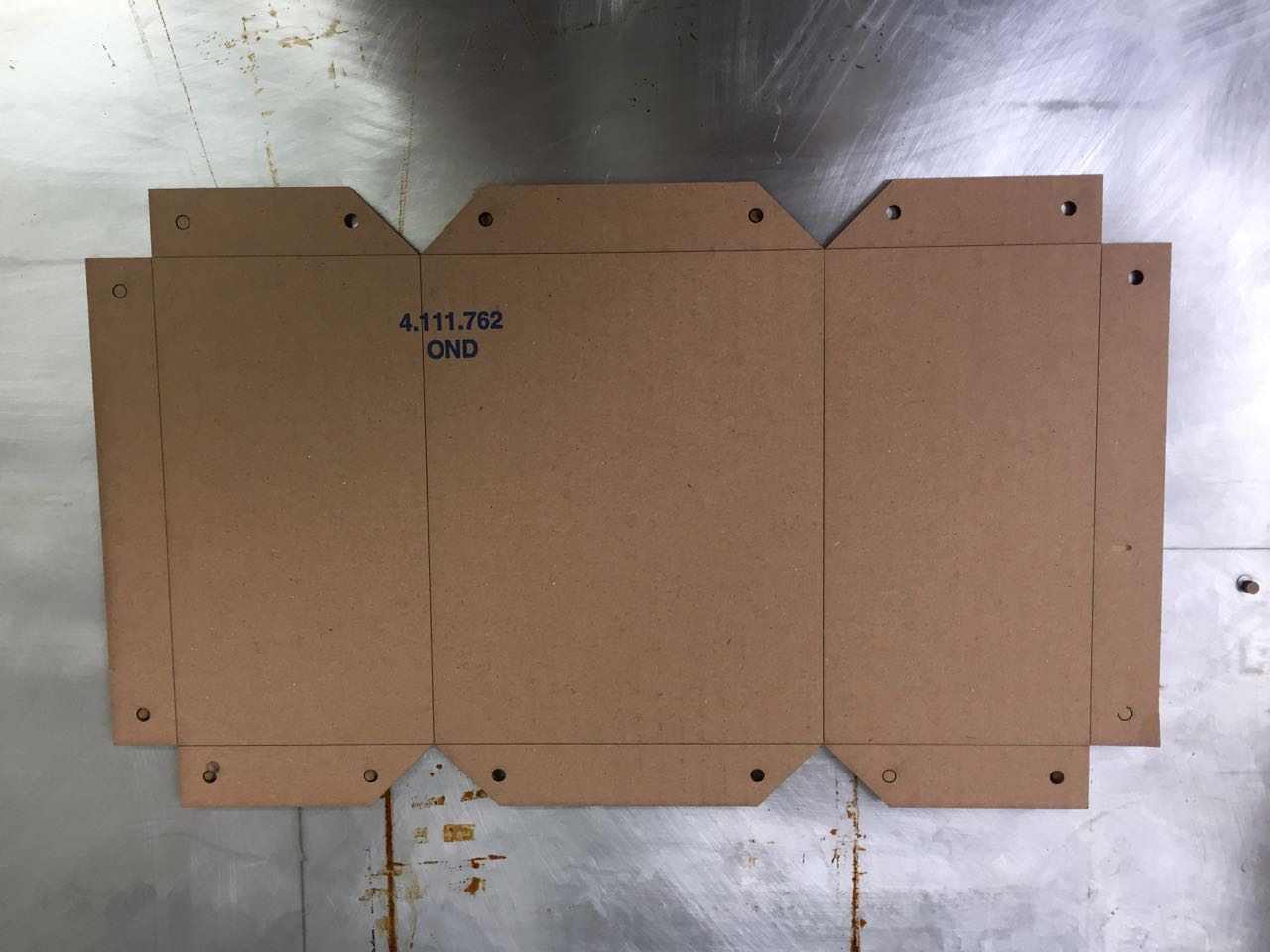
It consists of a central folded part, with flat side panels that cover the folding tabs. These could be attached by bolts or rivets.
Composite corner test
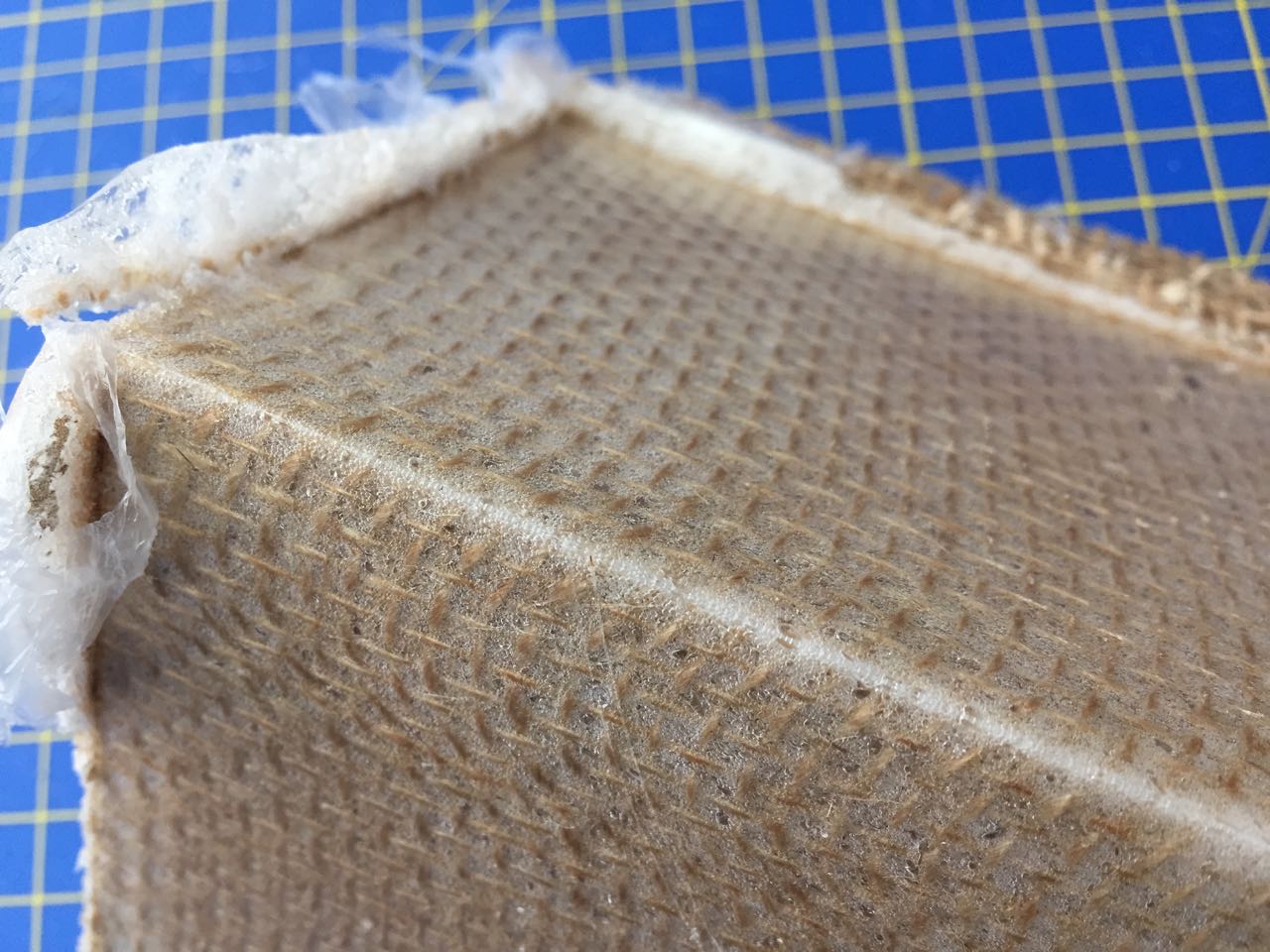
My box needs good sharp corners, flat faces, and a good even surface texture. So I tried a simple composite test to see if I could make a folded box using this method.
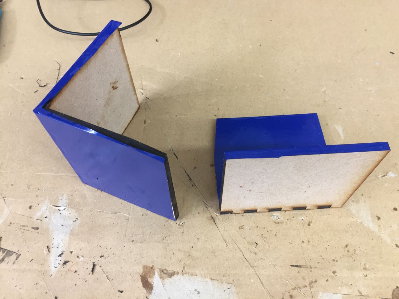
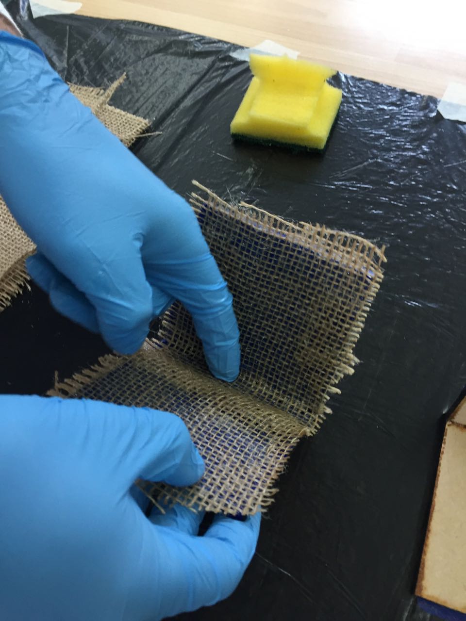
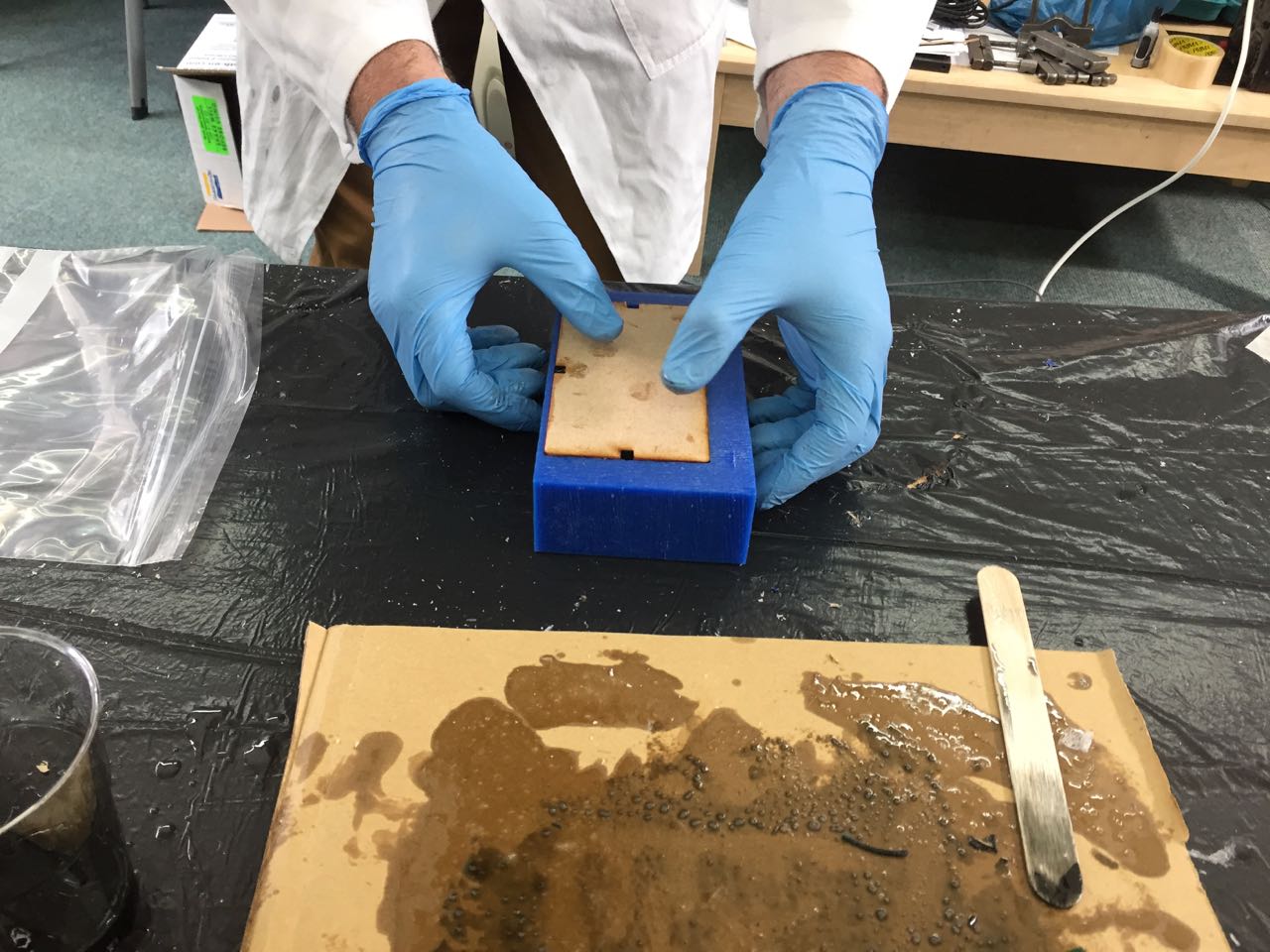
I made a simple corner mold out of MDF, covering the interiors faces with vinyl to aid release.
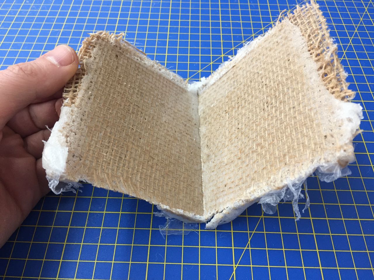
I used the 2-part Smooth-Cast 326 resin, and loose-woven hessian as my materials
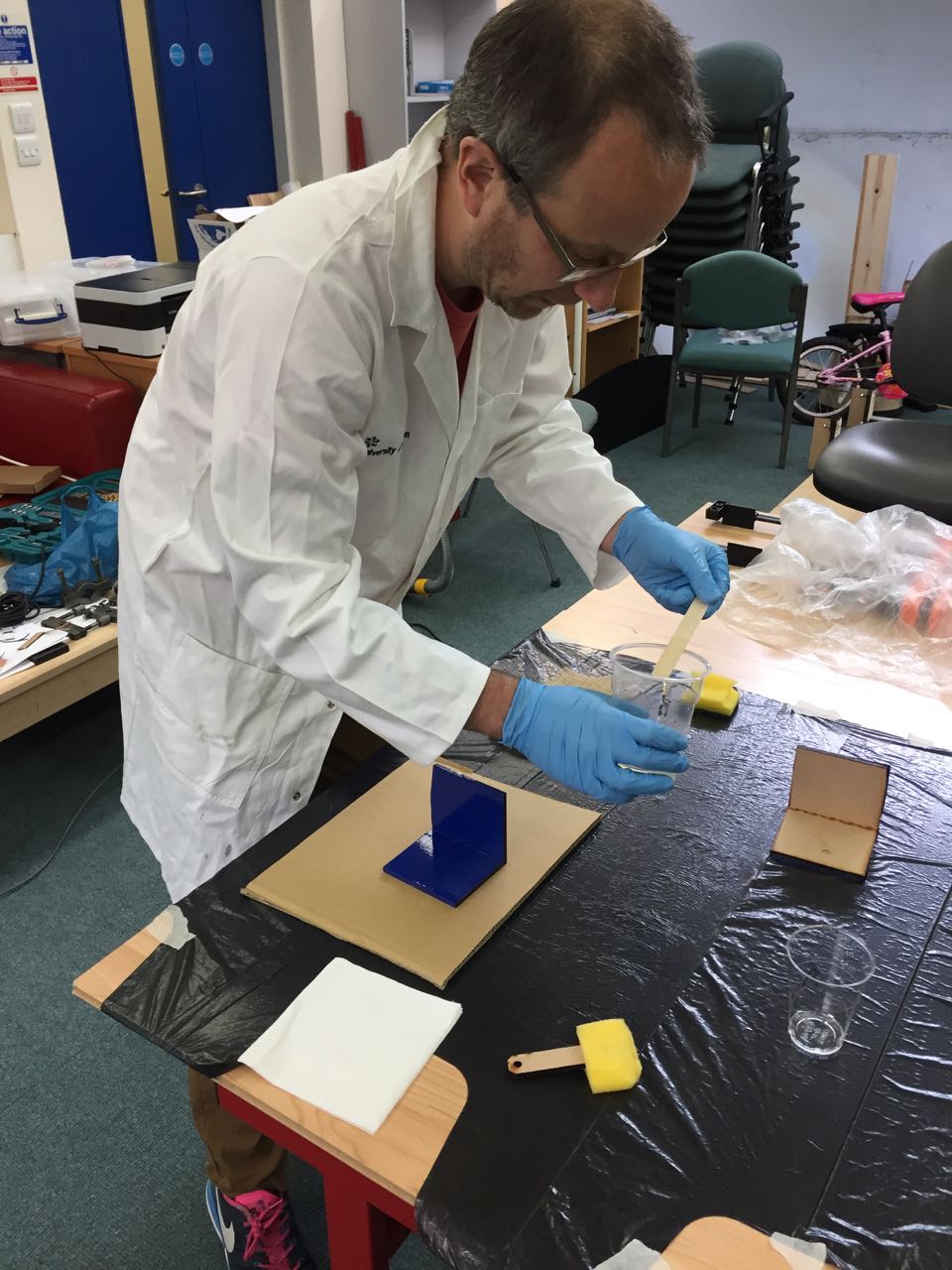
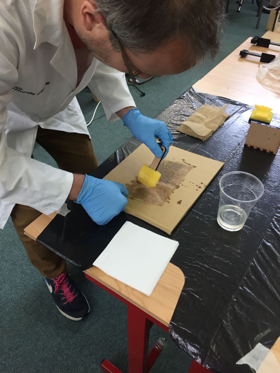
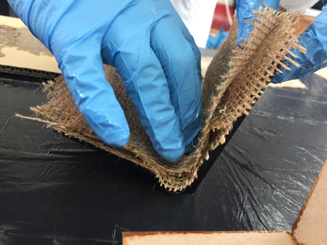
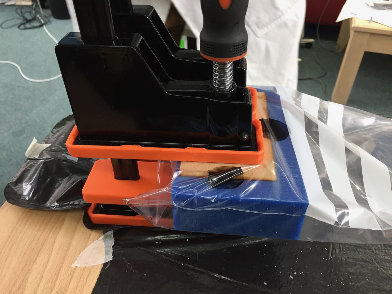
I applied 4 layers, then clamped the mold together inside
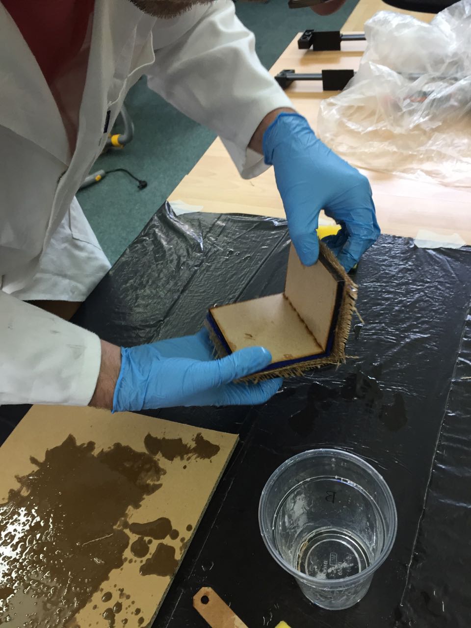
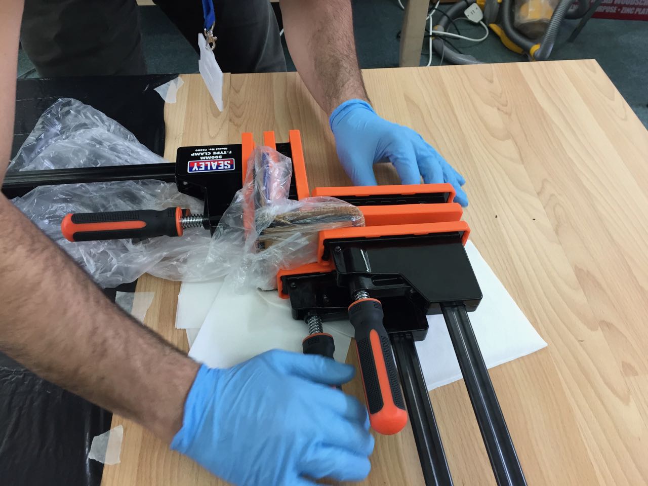
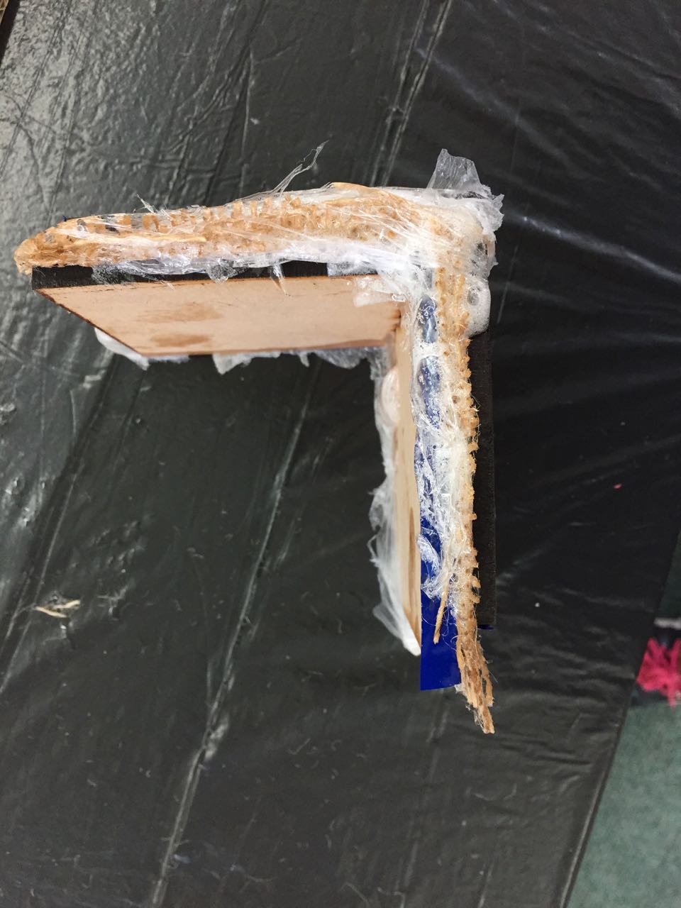
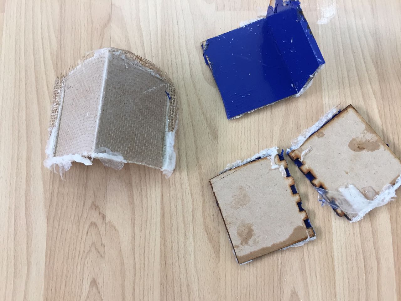
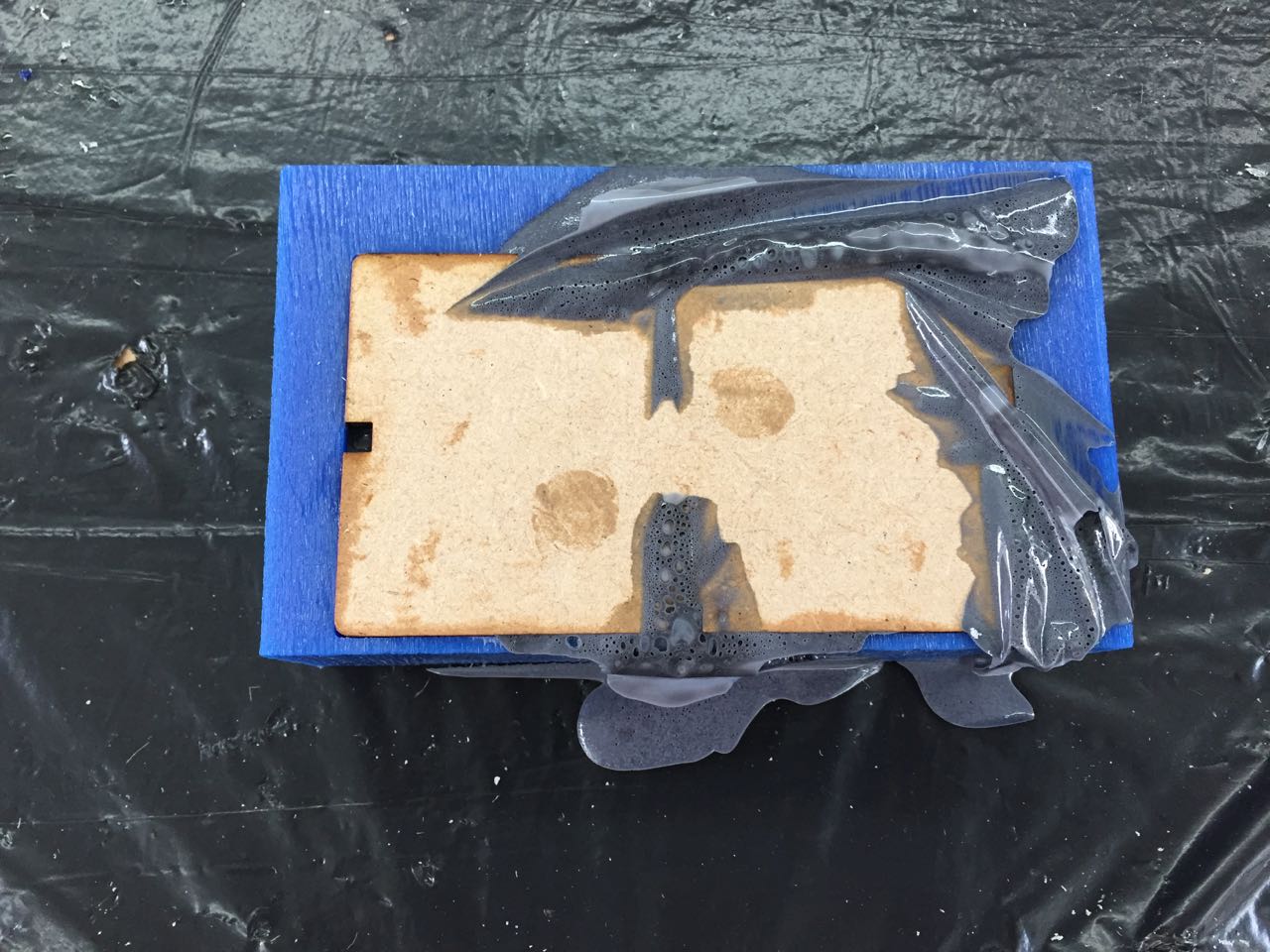
The process worked pretty well; the composite is strong and light, though too flexible for my needs. Also, some of the texture of the hessian has come through to the outside face. Maybe this could be solved with a different kind of resin.
I also had quite a lot of air in the mix, which deteriorated the outside surface.
Composite side panel test
Next, I wanted to try making a simpler part of the box, the side panels, which need to be strong, flat, have smooth faces, and resist damage.
I also wanted to try a different fibre, and also experiment with a sandwich construction, where the central layer is made of a lightweight material.
And I wanted to form the part with good surfaces out of the mold, so minimal post-processing would be necessary
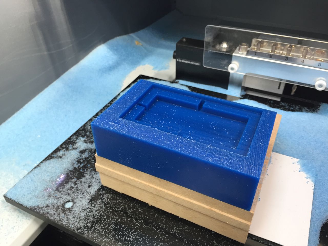
I used Fusion 360 to model a mold part. The part is simple – an 8mm thick rounded rectangle – I added vent holes to allow excess resin to escape in a more controlled way, and I used the laser cutter to cut the second part of the mold – a simple flat lid.
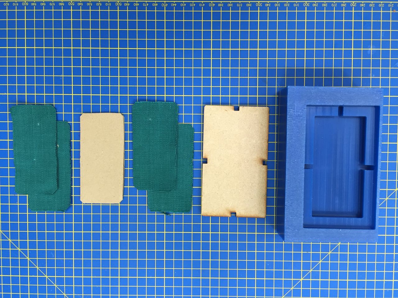
For the composite, I used 2 layers of cotton canvas, then a layer of corrugated cardboard, followed by two more layers of canvas.
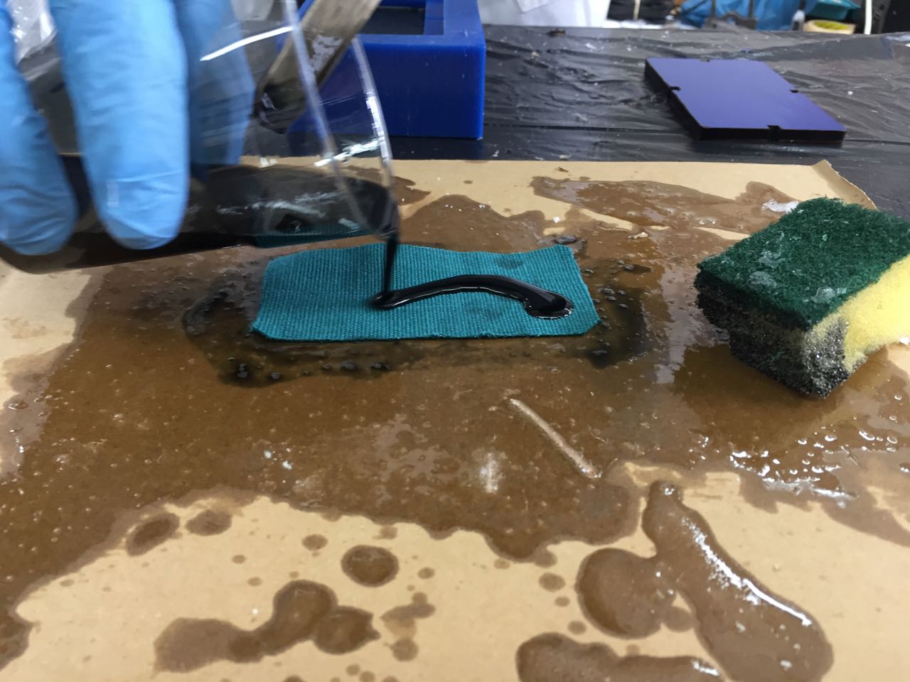
I used clamps to compress the mold
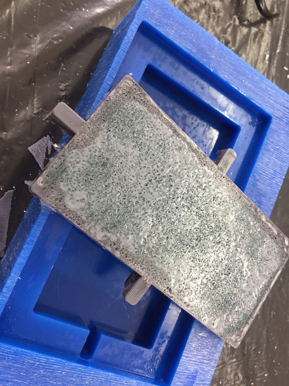
The part released fine, but had a very poor surface finish. Some of this could perhaps be remedied with a finishing coat, though there were many voids in the edges, which would need a lot of filler to fix.
## Folded metal test
Metal would be the ideal material for my project. I want to create a device that wouldn’t look out of place in the Nostromo, so a rough, heavy-duty, industrial casing is the kind of look I’m going for.
But metal is difficult to form with the tools we have easy access to at the lab, so I wanted to try some tests to see what is feasible.
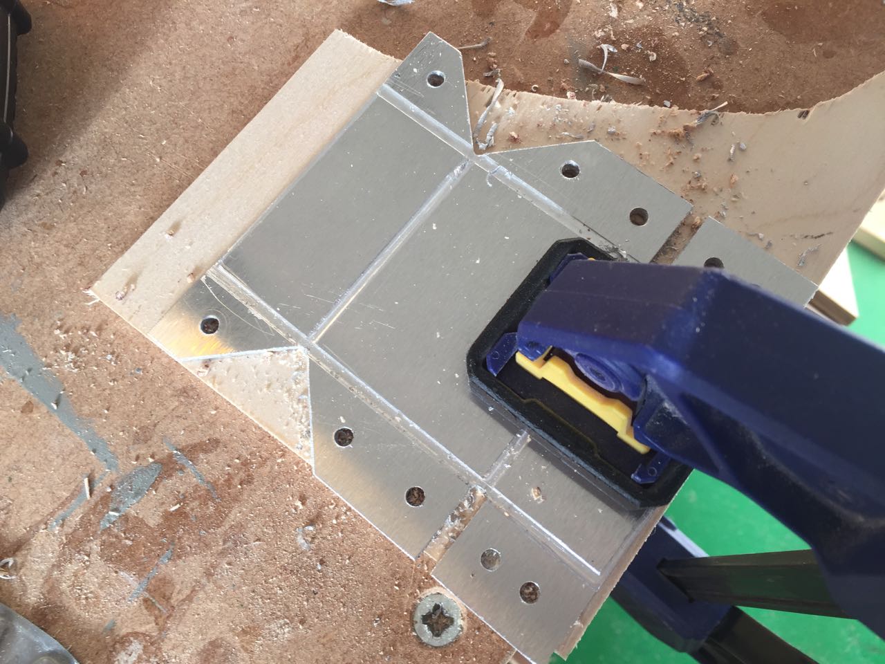
I started with a scrap piece of 2mm aluminium, and tried scoring it on the Roland MDX-50 so that I could create precise folds.
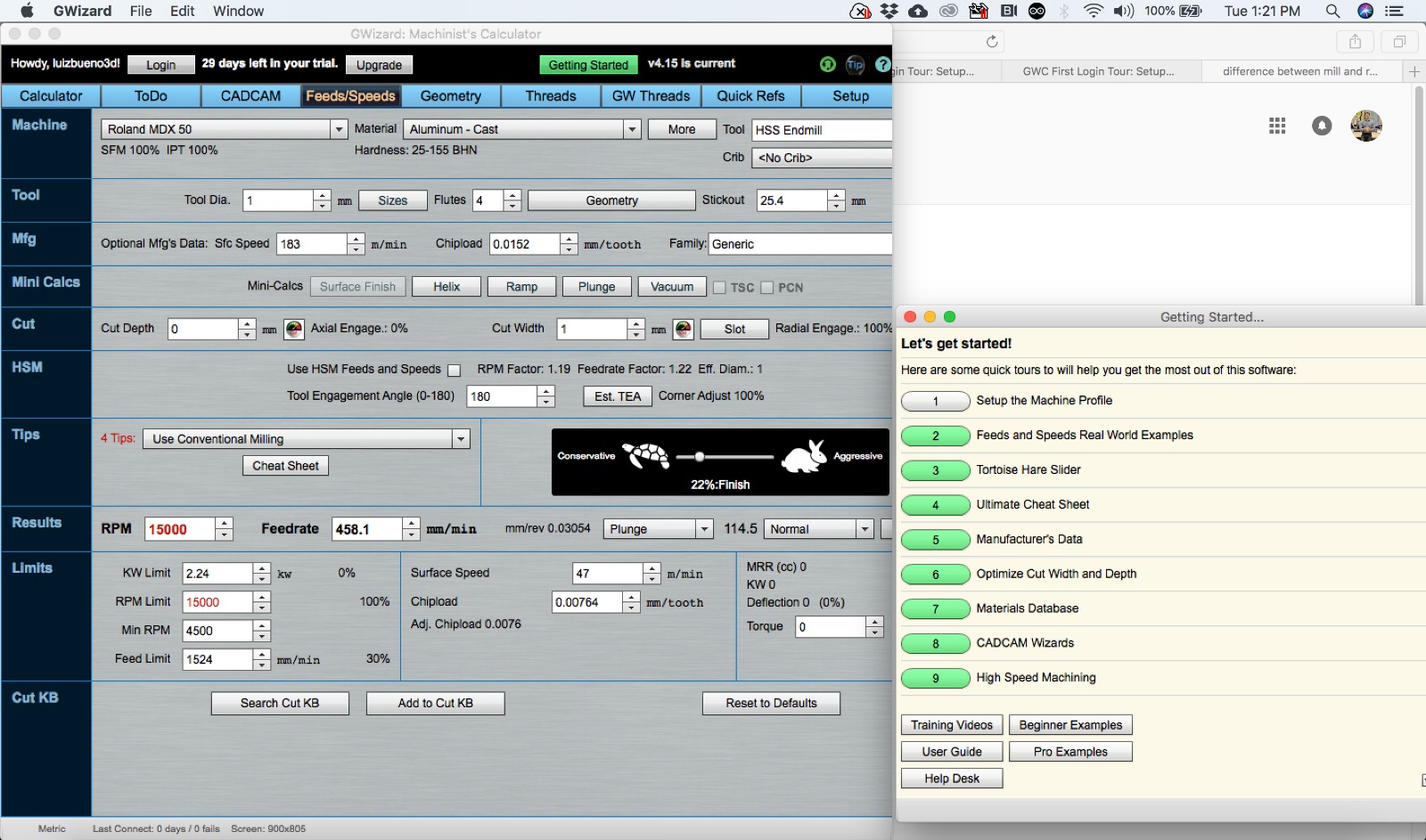
Luiz used GWizard software, to work out some initial feed and speed settings for our mill:
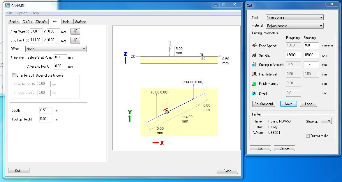
We used Roland ClickMILL software to create simple 0.5mm deep score lines across the Aluminium.
Test 1: 1mm flat-nosed bit, conservative settings
- Feed speed: 400mm/minute
- Spindle speed: 15000 rpm/minute
- Cut-in (depth of each pass): 0.25mm
I wanted to try a very thin score line, so used the smallest bit we have. I used a conservative (slow) feed speed, with a high spindle speed (the highest our mill is capable of).
It cut successfully, but the milling did not produce a lot of clean chips, with residue building up along the cut line.
Test 2: 1mm bit, higher speed
- Feed speed: 500mm/minute
- Spindle speed: 15000 rpm/minute
Next, I tried another score line, at a higher speed. But there was no noticeable improvement in quality. Also, the drill bit broke on this setting. So next, we moved to a 3mm bit.
Test 3: 3mm bit flat-nosed bit
- Feed speed: 600mm/minute
- Spindle speed: 15000 rpm/minute
- Cut-in (depth of each pass): 0.1mm
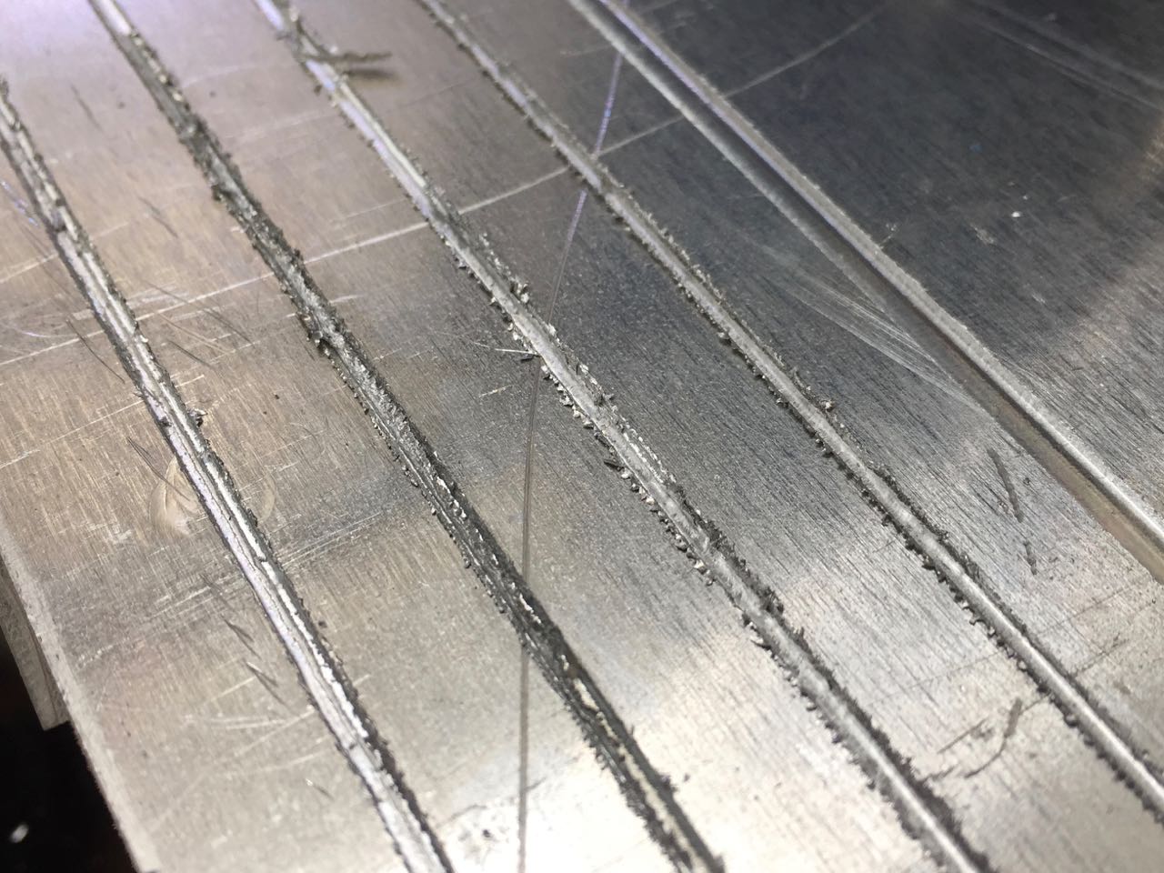
We also increased the speed for this test, and used a more conservative setting for the cut depth. The bit survived, but there was a lot of doughy swarf left in the cut line, which was being drawn into the drill bit as it passed back and forth.
Test 4: 3mm bit flat-nosed bit
- Feed speed: 900mm/minute
- Spindle speed: 15000 rpm/minute
- Cut-in (depth of each pass): 0.1mm
Finally, we tried the same bit with a higher speed. This gave the cleanest cut, with small chips flying from the bit rather than staying in the cut.
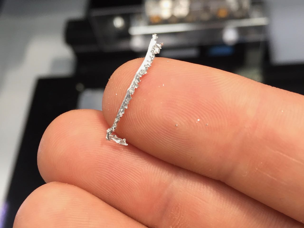
This is some of the soft waste material I removed from the test cuts.
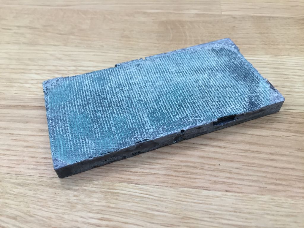
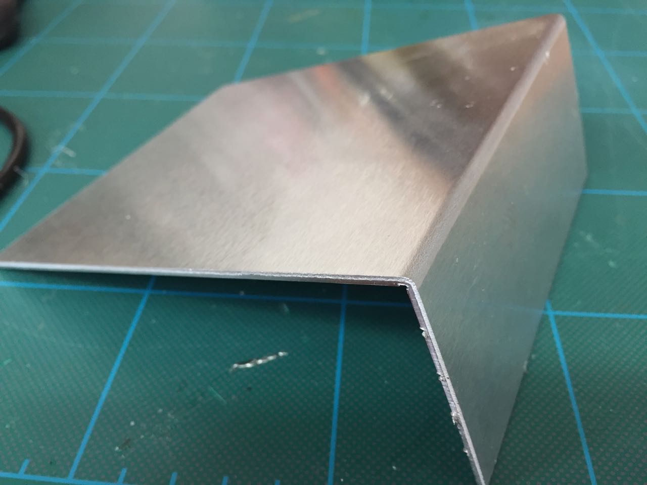
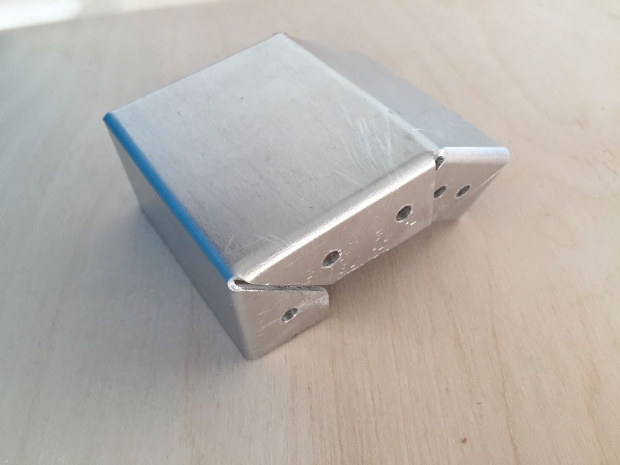
I was able to fold the metal in a vice just using my hands
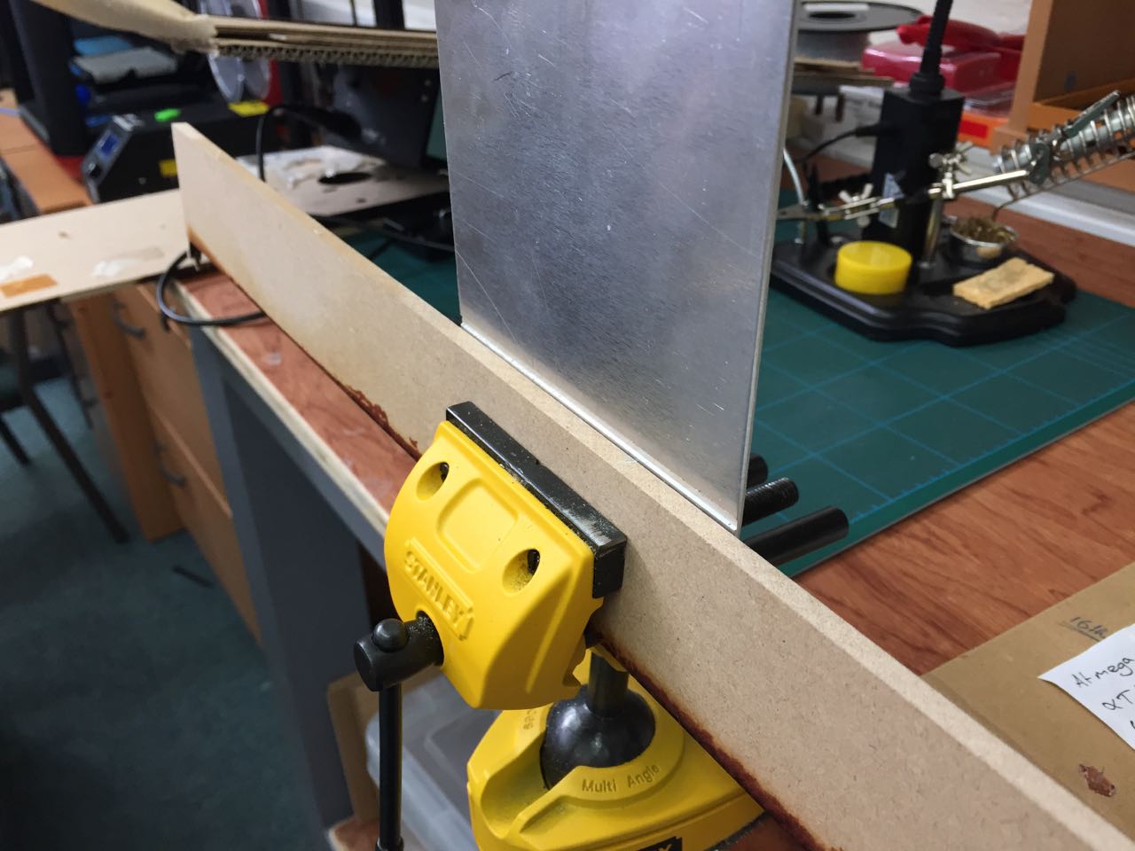
The fold was clean and precise. I was very happy with this result.
## A simple box
Next, I tried creating a simple folded box, to test the scoring method and also cutting out the outline of the part.
I used Illustrator to create the box net, and then exported the artwork as PNGs so I could create cutting paths in Fab Modules.
I started by cutting the outline. I used the same settings as in the final tests. Immediately we hit a problem as the machine tried to mill the 4mm assembly holes, and caused the spindle to ‘experience overcurrent’.
So I cancelled the job, and generated new paths without the holes. I also changed the speed from 15mm/sec down to 10mm/sec.
However, this again caused an overload, so for the next attempt, I used the speed override on the machine itself to reduce the feed speed down to about 40% (i.e. 4mm/sec).
At this stage, we decided to cancel the job again, so we could cut the score lines, as we were worried the part ould move in the process of it being cut out. I narrowly avoided the mistake of setting the cut depth to the same as the material depth.
Then I went back ot the outline, and I was able to cut out the whole part in about an hour.
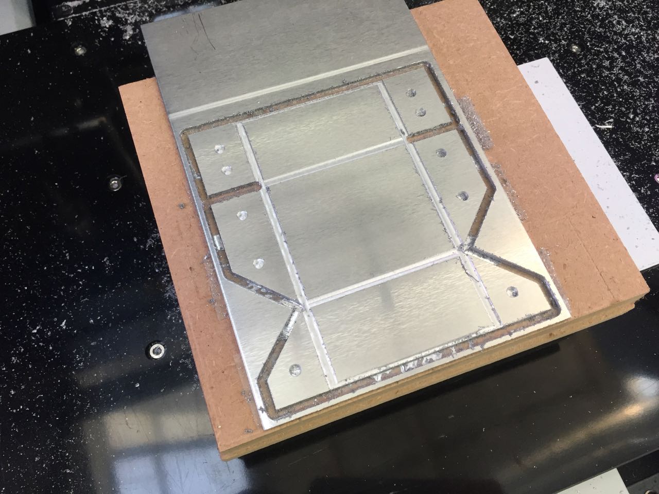
I used an electric drill to cut the assembly holes and a file to clean up the cut edges.
Then I used a vice and pliers to fold the box. One set of corners, with diagonal cuts, folded well, the other set (with overlapping tabs) didn’t. I could probably make these work by offsetting the score lines for these tabs.
Files
Mold parts for side panel test
Folded metal test net: