Week 14 - Networking and communications
Tests of I2C communication on Arduino (and DIY Arduino-style) boards
Experiment 1: Connecting 2 Arduino boards
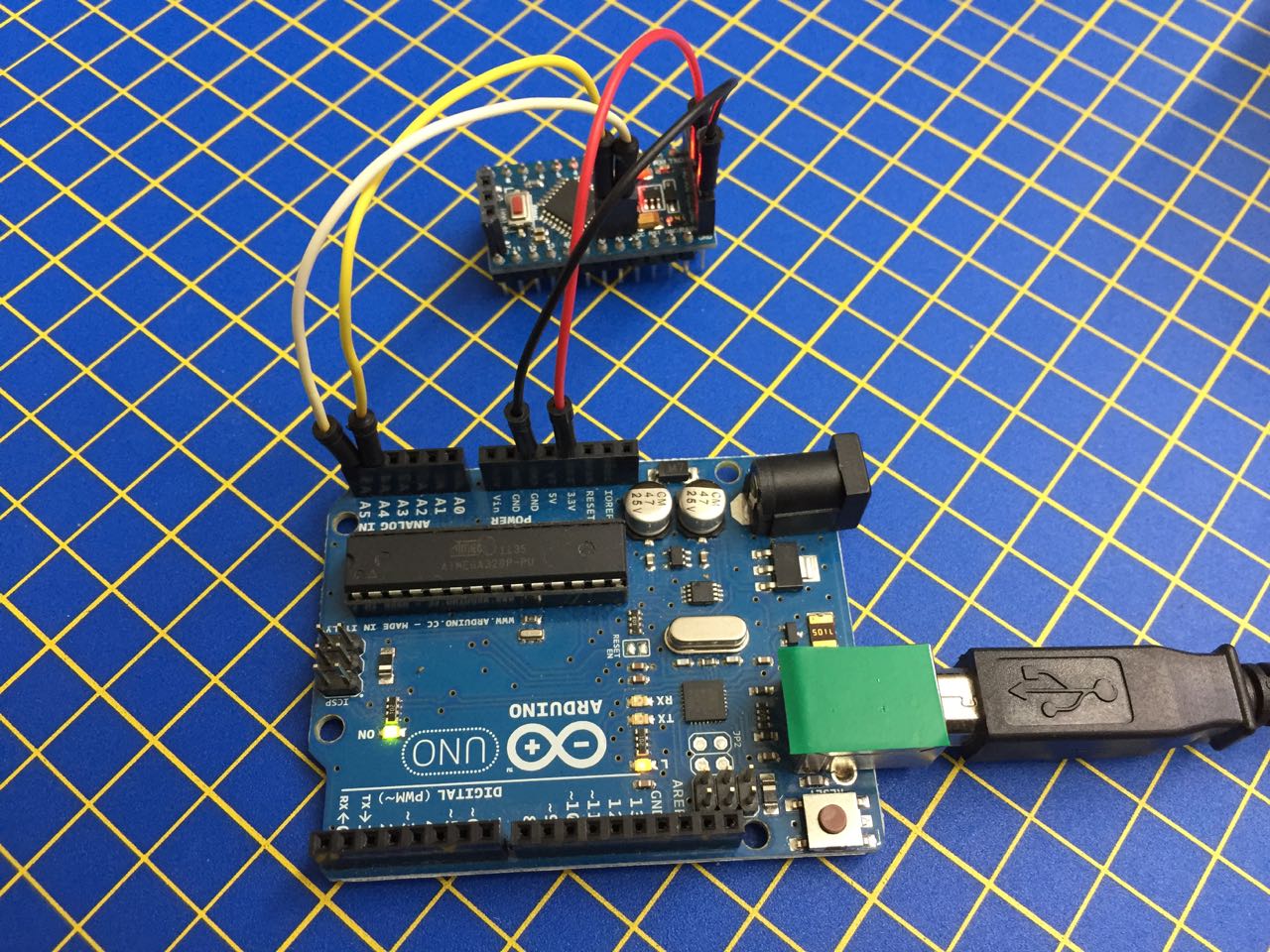
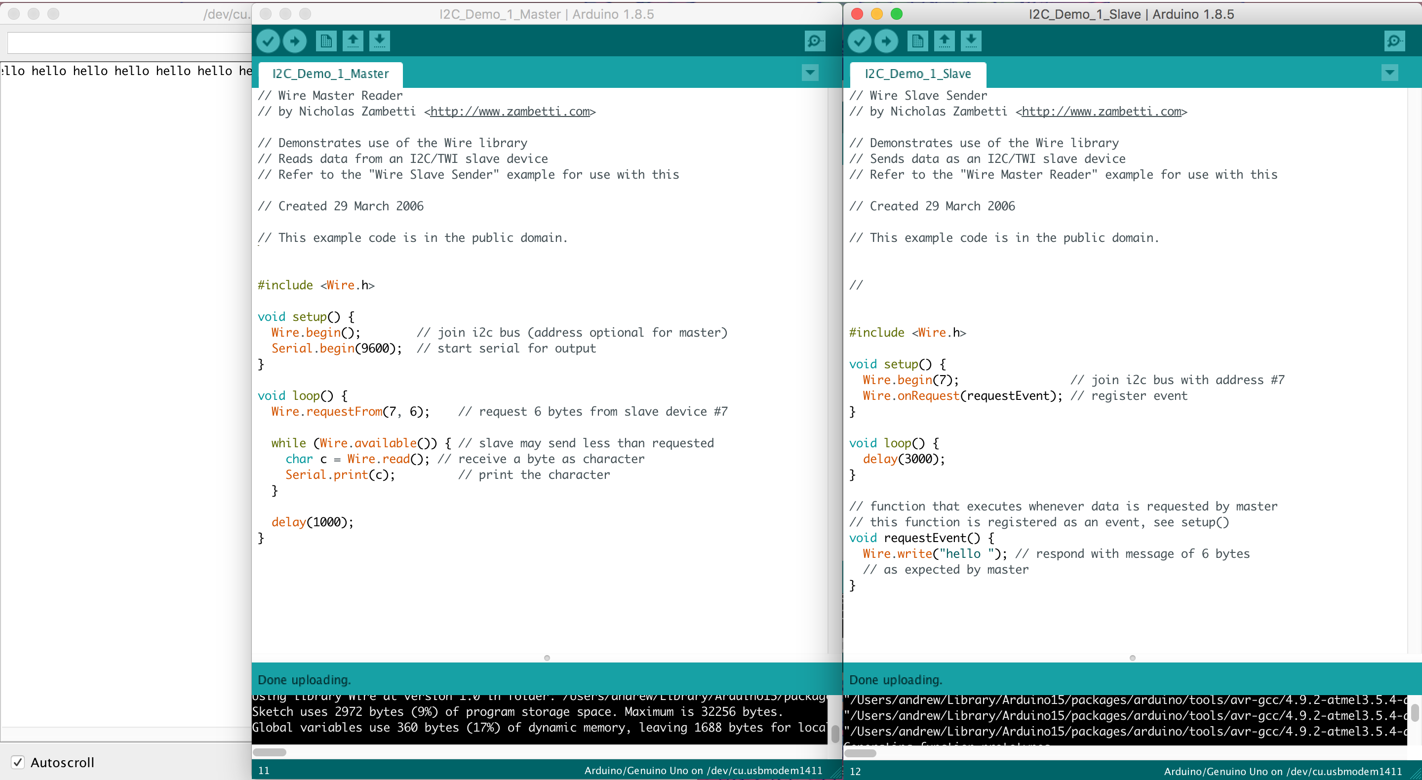
I used a commercial Arduino Uno and Arduino Pro Miny board together with demo files from the Arduino Wire library for I2C. I connected my 2 boards as per the schematic on the example code page:
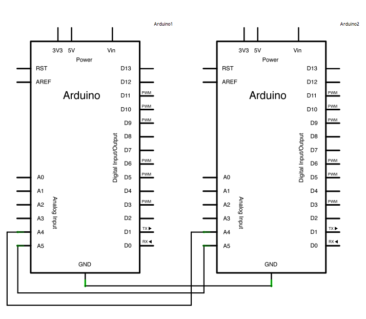
The serial clock pin (SCL, 5) and serial data pin (SDA, 4) are connected between each board, as are GND, but because the Pro Mny runs at 3.3V, I used the 3.3V VCC on the Arduino Uno to connect VCC.
I was able to get these two boards to communicate sending serial data (characters) back and forth (using the same code as experiment 2, below).
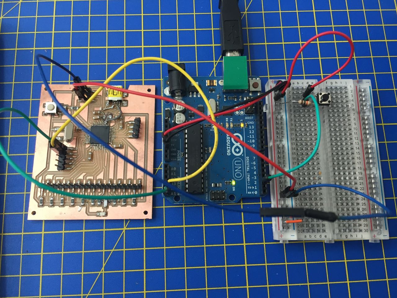
Experiment 2: Connecting an Arduino to my Input Devices board
The board I made for the Input Devices assignment is essentially an Arduino Leonardo, so I was able to replicate the first experiment with these two boards using the same code. I just had to figure out how to access the pins on my board. Some of these are exposed on the ISP header.
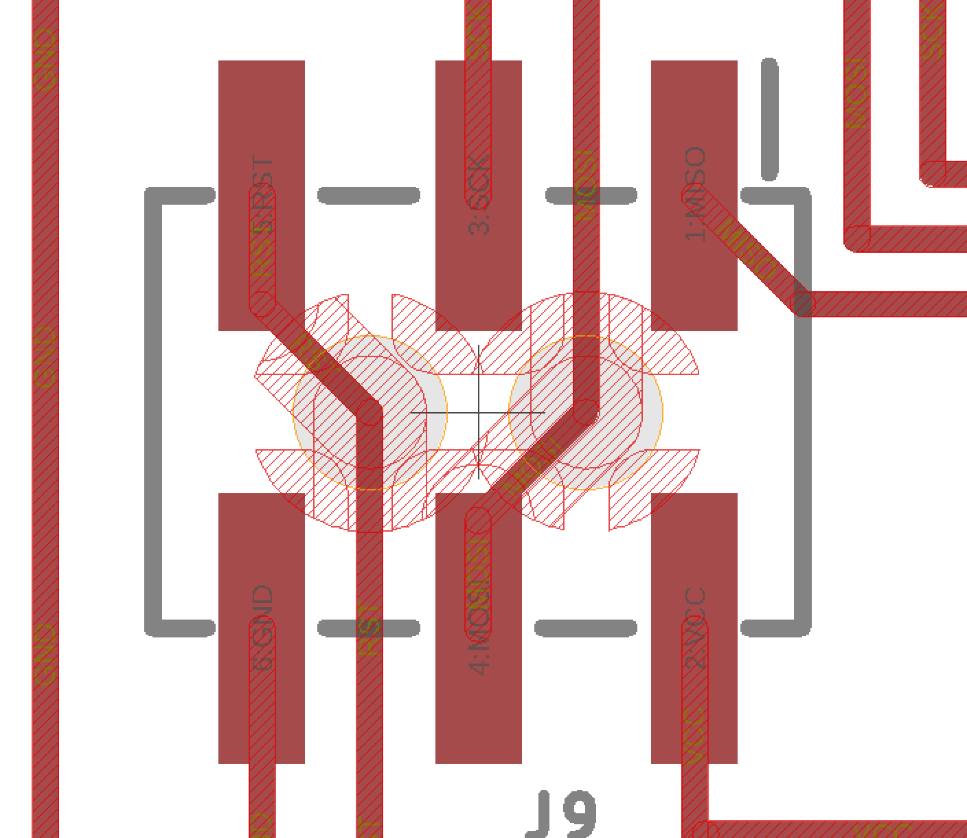
- VCC: ISP header bottom right
- GND: ISP header botom left
The I2C pins themselves are exposed on my 5-pin header
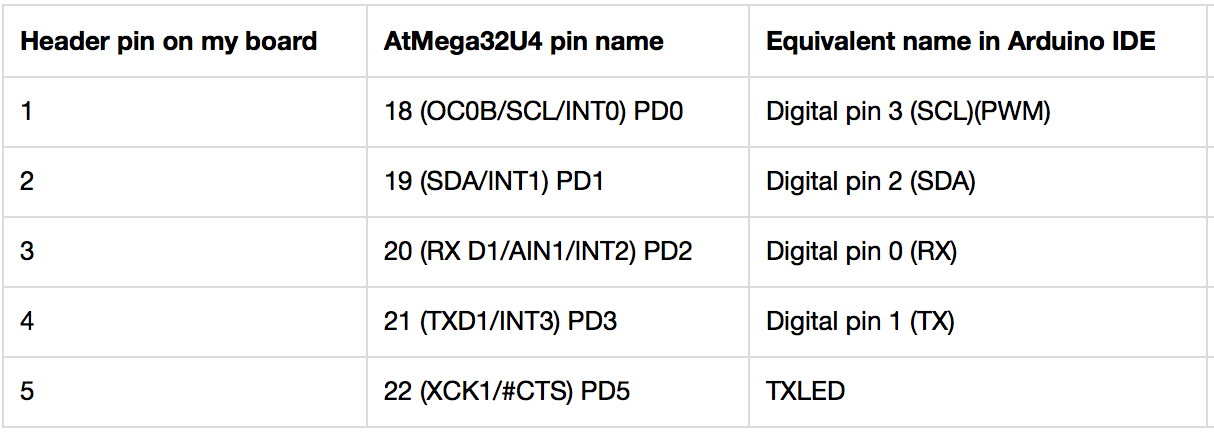
Using the same code as before (attached below), I was able to send data back and forth again.
Experiment 3: Trying another way to control my Input Devices board
While these experiments showed I was able to communicate between the boards, I wanted to try one more test, to see if I could use a physical input on one, to control an output on another. So I wired up a buton to my Arduino Uno, and adapted some of the demo code so I could use it to control an LED on my Input Devices board.
My previous code used Wire.requestFrom() and Wire.onRequest() to request and listen for data:
Master:
void loop() {
  Wire.requestFrom(7, 6);       // request 6 bytes from slave device #7

  while (Wire.available()) {    // slave may send less than requested
    char c = Wire.read();       // receive a byte as character
    Serial.print(c);            // print the character
  }

  delay(1000);
}
Slave:
void setup() {
  Wire.begin(7);                // join i2c bus with address #7
  Wire.onRequest(requestEvent); // register event
}

void loop() {
  delay(3000);
}

// function that executes whenever data is requested by master
// this function is registered as an event, see setup()
void requestEvent() {
  Wire.write("hello ");         // respond with message of 6 bytes as expected by master
}
My new code uses Wire.beginTransmission() and Wire.endTransmission() on the master to send the commands to the slave:
Master:
void loop() {

  // read the state of the pushbutton value:
  buttonState = digitalRead(buttonPin);

  if (buttonState == 1) {

    // turn LED on:
    Wire.beginTransmission(7); // address of slave is 7
    Wire.write(1);             // sends value byte
    Wire.endTransmission();    // stop transmitting

    } else {

    // turn LED off:
    Wire.beginTransmission(7); // address of slave is 7
    Wire.write(0);             // sends value byte
    Wire.endTransmission();    // stop transmitting
   }
}
Slave:
void setup() {

  // initialize the LED pin as an output:
  pinMode(ledPin, OUTPUT);
  digitalWrite(ledPin, LOW);

  Wire.begin(7);                   // join i2c bus with address #7

  // Attach a function to trigger when something is received.
  // From http://www.instructables.com/id/I2C-between-Arduinos/
  Wire.onReceive(receiveEvent);

}

void receiveEvent(int bytes) {
   x = Wire.read();                // read one character from the I2C
}

void loop() {
  if (x == 0) {
      digitalWrite(ledPin, LOW);   // received an OFF command
  }

  if (x == 1) {
      digitalWrite(ledPin, HIGH);  // received an ON command
  }
}
Here’s a video of it working:
Group assignment
We used I2C to communicate between different boards from the group
Files
Experiments 1 and 2: sending serial data back and forth:
Experiment 3: sending a command from master to slave: