Week 13 - Application interfaces
I’m working towards combining the elements of my final project, in this case, starting with connecting an SD card reader and LCD screen to my board, and displaying information from the SD card on that screen.
Connecting an SD card breakout board
I have a simple board with just an SD card slot and pins on a header. The first step is to figure out how to connect these pins. This board use SPI to communicate wit th Arduino. From the SPI docs:
Serial Peripheral Interface (SPI) is a synchronous serial data protocol used by microcontrollers for communicating with one or more peripheral devices quickly over short distances. It can also be used for communication between two microcontrollers. With an SPI connection there is always one master device (usually a microcontroller) which controls the peripheral devices. Typically there are three lines common to all the devices:
- MISO (Master In Slave Out) - The Slave line for sending data to the master,
- MOSI (Master Out Slave In) - The Master line for sending data to the peripherals,
- SCK (Serial Clock) - The clock pulses which synchronize data transmission generated by the master and one line specific for every device:
- SS (Slave Select) - the pin on each device that the master can use to enable and disable specific devices.
These acronyms can be confusing. It seems that:
- SCK = CLK (Serial Clock)
- CS = SS (Chip Select, or Slave Select)
First, I tried the board with a standard (commercial) Arduino board. I connected the pins as follows:
- MOSI - pin 11
- MISO - pin 12
- CLK - pin 13
- CS - pin 4
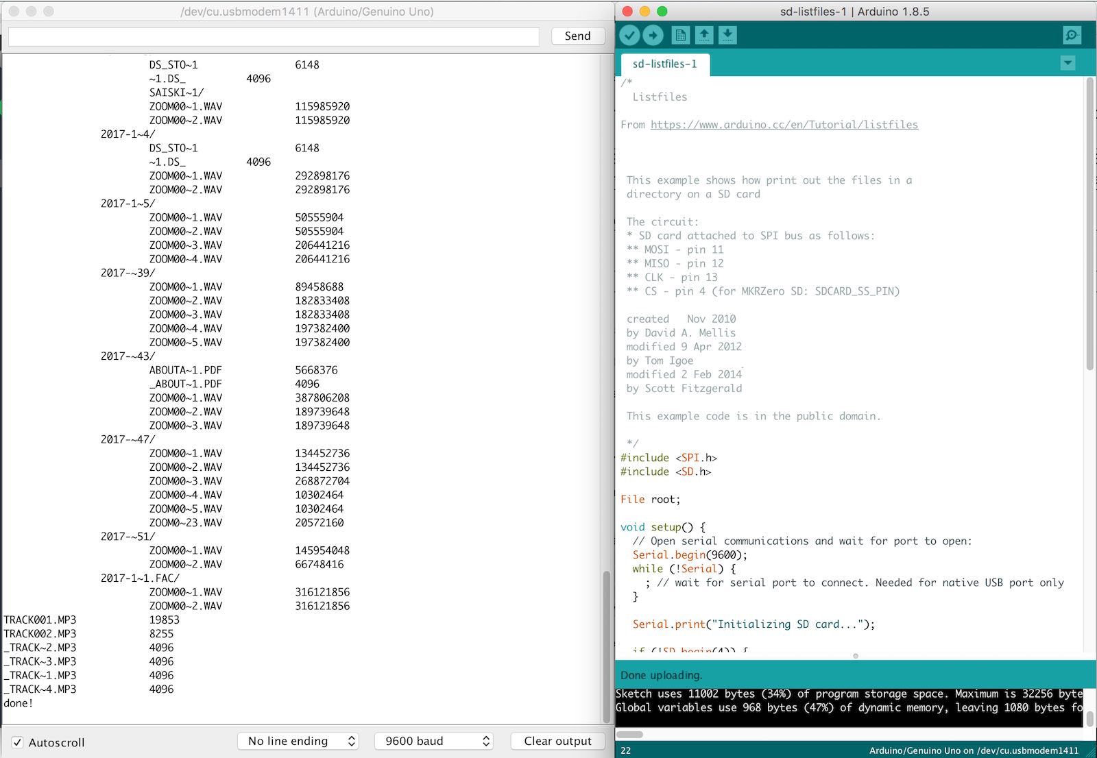
I also connected GND and 5V on my board. Using an SD card formatted as FAT16, I was able to read the contents using the example ‘Listfiles.ino’ sketch that comes with the SD.h library:
Formatting SD cards
By default, macOS puts all sorts of hidden files on an SD card as part of its search/indexing functionality. When read in a FAT16 reader, these show up as extraneous files.
I was able to find a way to format my card to remove these files.
To format the SD card, you will need the path to the SD card device and the SD card device number.
- Insert the SD Card into a card reader.
- If you don’t know how to find the device number of the SD Card, here is one way to do it: 2b. Open Disk Utility 2c. Highlight the SD Card device (upper icon), not the SD Card volume (lower icon) 2d. Click Erase at the top of the window 2e. Select Volume Format: MS-DOS (FAT) Click Erase… > Click Erase The SD Card Volume Name will change to the UNIX device number e.g. “disk5s1”. Note this number as it will change by itself to “Untitled”. It is now formatted in MS-DOS FAT 32. We need to reformat it in FAT 16. Once you have the device number of the SD Card, you need the path to the SD card device.
- For my Mac, the path to devices is “/dev”. In a terminal window: type “cd /dev” and hit the “Return” key to go to the “dev” directory. Then type “ls” (with a lower case L) and “Return” key. You should see the SD Card device number listed. Formatting the SD Card in FAT 16:
- In Disk Utility, highlight the SD Card device and click Unmount at the top, not Eject. The desktop icon of the SD card will disappear.
- Go to the Terminal window. Be careful to type the following command with the correct letter case and spacing. Again, make sure you type the correct device number and path as you can very easily erase your hard drive in UNIX. Type the command: newfs_msdos -F 16 (path to SD Card device)/(SD Card device number) e.g. newfs_msdos -F 16 /dev/disk5s1 and hit the “Return” key.
- If you get just a new prompt (or a prompt with some warnings, e.g. below), the command executed successfully. You can remove the SD Card; it is now formatted in FAT 16. You can verify this in Disk Utility after mounting the SD Card. If you get some instructions on the newfs_msdos command with a new prompt, the command did not execute. Make sure you enter the command with the correct case and spacing. Hint: to re-enter a previous command you typed, hit the up arrow repeatedly. For more information, type: “man newfs_msdos”. Scroll with arrow keys. Type “q” to quit and return to prompt.
For me, the Terminal command was:
cd /dev
sudo newfs_msdos -F 16 disk2s1
Again, I was able to run some of the example sketches with this card using my Arduino and also using my own Leonardo board that I made for Output Devices week.
Adding an LCD display
I have an LCD bitmap display that uses a KS0108 controller.
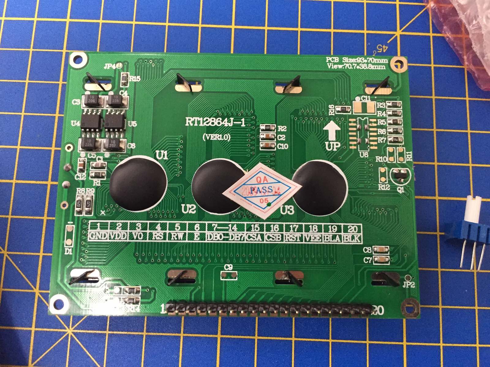
This kind of display can be driven with the openGLCD Arduino library. The documentation includes a pinout table for a KS0108 panel. From this, I was able to create a pinout mapping table that also worked for a Leonardo board, then map this to the pins on an ATMega32U4, and then to the header configuration on my own board:
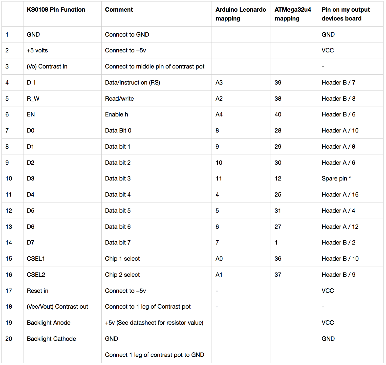
For an explanation of Header A, Header B, etc. see my Output Devices assignment writeup
In the course of wiring the LCD panel up, I realised that I needed to access a pin that I had not brought out to my header (ATMega32u4 pin 12). Fortunately, I was able to solder on a single header pin to some exposed (isolated) copper on the board, and bridge this to pin 12, so I could use this pin.
I was able to run the demo sketches from the openGLCD library to confim hat my board worked.
Connecting the SD card reader to the LCD display.
I combined libraries and example code for:
- reading an SD card (from https://www.arduino.cc/en/Tutorial/listfiles)
- displaying text on an LCD screen (from openGLCD Library - Hello World sketch)
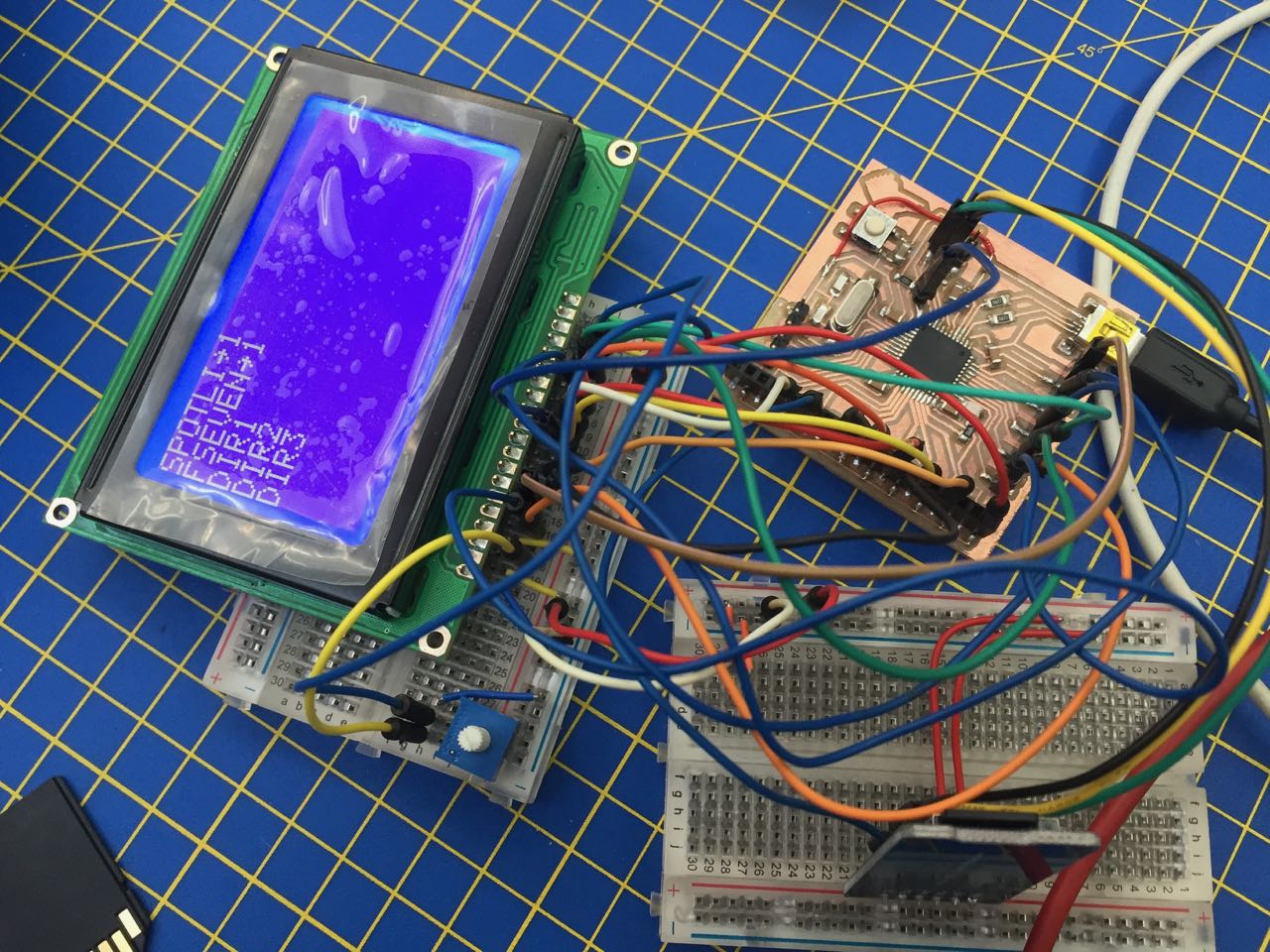
To read the root level directories on an SD card, and print the listing to my LCD screen (full sketch at the bottom of this page)
// SD card setup
#include <SPI.h>
#include <SD.h>
File root;
String fileList = "Blah";

// LCD screen setup
#include <openGLCD.h>


void setup() {
  // Open serial communications and wait for port to open:
  Serial.begin(9600);
  while (!Serial) {
    ; // wait for serial port to connect. Needed for native USB port only

  // Initialize the GLCD
  GLCD.Init();

 // Select the font for the default text area
  GLCD.SelectFont(System5x7);
  }


  Serial.print("Initializing SD card...");

  if (!SD.begin(12)) {
    Serial.println("initialization failed!");
    while (1);
  }
  Serial.println("initialization done.");

  root = SD.open("/");

  printDirectory(root, 0);

  Serial.println("done!");
}


void loop() {
  // nothing happens after setup finishes.
}

void printDirectory(File dir, int numTabs) {
  // loop through all the files in the root directory
  while (true) {

    File entry =  dir.openNextFile();
    if (! entry) {
      // no more files
      break;
    }

    // I only want it to print directories, not files
    if (entry.isDirectory()) {
      //  Serial.println("/");

     for (uint8_t i = 0; i < numTabs; i++) {
        Serial.print('\t');
      }

      // entry.name() is the title of each file or folder it finds
      Serial.println(entry.name());
      // Also print it to the LCD screen
      GLCD.println(entry.name());

      // this loop recursively goes through directories and also prints what it finds inside
      // I don't want this, so comment it out
      // printDirectory(entry, numTabs + 1);

    } else {
      // ignore files
    }
    entry.close();
  }
}
This worked:
Next steps
A screen like this could be useful in my final project, however, rather than displaying (unhelpful 8.3 formatted) directory names, I’d like it to display human-readable information like album name or artist, pulled from, say the ID3 tag information in an MP3 file. Or perhaps a text file at the root of each directory.
It might also be helpful to make the display interactive, for example, allowing the user to step through and select items from the display – though it’s worth noting that this is not the point of my final project, where album selection should be made entirely by media card.
## Interfacing with a desktop computer using Processing
I also experimented with Processing, to see if I could control a display on my Mac using external hardware. I had the idea of reading the media cards from my final project, identifying which card has ben placed in the device, and then rendering an image of that card on the computer screen.
I started by using an Arduino and a breadboard with 3 buttons. By pressing the buttonds, I could change the display of boxes on the canvas generated by Processing.
After this prototype, I shifted over to using the hardware in my final project: an ATMega32u4-based DIY board, connected to a DIY breakout board containing 8 photo-interrupt sensors connected to a PISO shift register.
The key difference here, is that the data I was getting over serial was a single 3 digit number (range 0-255), as opposed to a convenient comma-separated string of 1s and 0s. SO I had to do some extra work in Processing to convert this into a useful format.
However, I was able to get it working, and had a lot of fun figuring out Processing for the first time.
Group assignment
Comparing interface and application programming tools
Group assignment docs PDF export
Files
Arduino SD — LCD test file:
Arduino and breadboard — Processing test
DIY board — Processing test