Week 9 - Program your board to do something
Programming boards with as many different programming languages and programming environments as possible
Programming the Hello World board in the Arduino IDE
I used
- Environment: Arduino IDE
- Written in: Arduino library (C with some encapsulated libraries)
- Uploaded with: AVRDude (built into the IDE)
My Arduino sketch:
/*
  Button

  Turns on and off a light emitting diode(LED) connected to digital pin 13,
  when pressing a pushbutton attached to pin 2.

  The circuit:
  - LED attached from pin 13 to ground
  - pushbutton attached to pin 2 from +5V
  - 10K resistor attached to pin 2 from ground

  - Note: on most Arduinos there is already an LED on the board
    attached to pin 13.

  created 2005
  by DojoDave <http://www.0j0.org>
  modified 30 Aug 2011
  by Tom Igoe

  This example code is in the public domain.

  http://www.arduino.cc/en/Tutorial/Button
*/

// constants won't change. They're used here to set pin numbers:
const int buttonPin = 7;     // the number of the pushbutton pin
const int ledPin =  2;      // the number of the LED pin

// variables will change:
int buttonState = 0;         // variable for reading the pushbutton status

void setup() {
  // initialize the LED pin as an output:
  pinMode(ledPin, OUTPUT);
  // initialize the pushbutton pin as an input:
  pinMode(buttonPin, INPUT);
}

void loop() {
  // read the state of the pushbutton value:
  buttonState = digitalRead(buttonPin);

  // check if the pushbutton is pressed. If it is, the buttonState is HIGH:
  if (buttonState == HIGH) {
    // turn LED on:
    digitalWrite(ledPin, HIGH);
  } else {
    // turn LED off:
    digitalWrite(ledPin, LOW);
  }
}
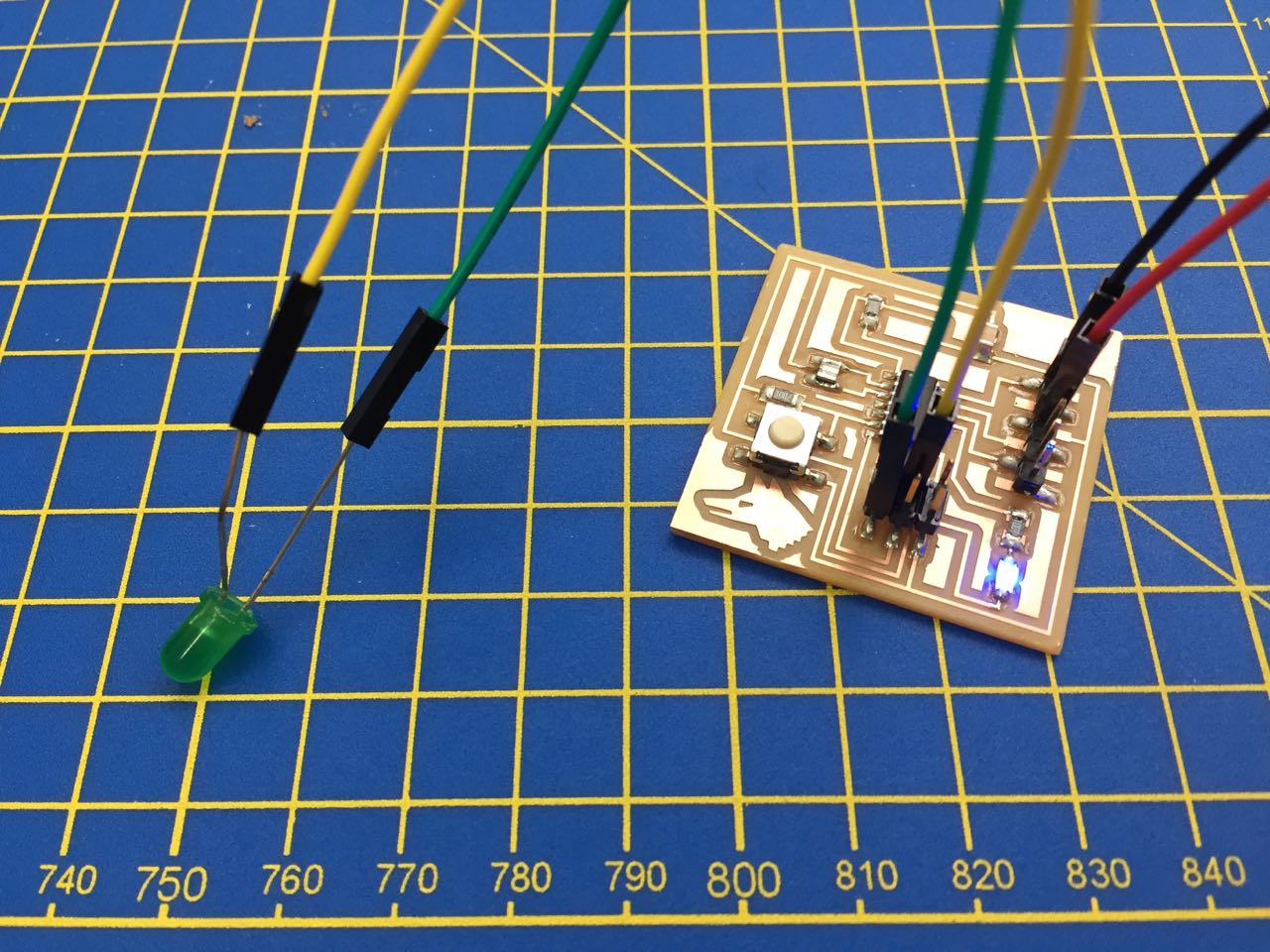
(My LED is wired to pin 2, and my button to pin 7 (and then to VCC, so when pressed it sends a digital HIGH signal).
Multitasking, and getting an extra pin
I know in my project I will have to rund several systems at once, so I ned to understnd how to get my board to multitask. There are some good instructions here. I used this code to accomplish a few things:
- Using millis() instead of delay() to control time
- Encapsulating logic into functions, classes and constructors to make my code more portable and modular
- Using a spare pin on the ATTiny44, which you can access after you’ve programmed the board and removed the programmer from the header (the SCK pin which is connected to PA4 on the ATTiny, which can be accessed with pin number 4)
class Flasher
{
  // Class Member Variables
  // These are initialized at startup
  int ledPin;      // the number of the LED pin
  long OnTime;     // milliseconds of on-time
  long OffTime;    // milliseconds of off-time

  // These maintain the current state
  int ledState;                 // ledState used to set the LED
  unsigned long previousMillis;   // will store last time LED was updated

  // Constructor - creates a Flasher
  // and initializes the member variables and state
  public:
  Flasher(int pin, long on, long off)
  {
  ledPin = pin;
  pinMode(ledPin, OUTPUT);

  OnTime = on;
  OffTime = off;

  ledState = LOW;
  previousMillis = 0;
  }

  void Update()
  {
    // check to see if it's time to change the state of the LED
    unsigned long currentMillis = millis();

    if((ledState == HIGH) && (currentMillis - previousMillis >= OnTime))
    {
      ledState = LOW;  // Turn it off
      previousMillis = currentMillis;  // Remember the time
      digitalWrite(ledPin, ledState);  // Update the actual LED
    }
    else if ((ledState == LOW) && (currentMillis - previousMillis >= OffTime))
    {
      ledState = HIGH;  // turn it on
      previousMillis = currentMillis;   // Remember the time
      digitalWrite(ledPin, ledState);   // Update the actual LED
    }
  }
};


Flasher led1(4, 50, 600); // use pin on ISP header to light second external LED
Flasher led2(2, 350, 350);

void setup()
{
}

void loop()
{
  led1.Update();
  led2.Update();
}
Adding an interrupt
Again, crucial for my project – I need to be able to, for example, stop and start music, at any point. I believe interrupts are used for this purpose.
According to the ATTiny44 datasheet, all the pins can be used as interrupts, including PA7, which my switch is connected to:
Port A, Bit 7 – ADC7/OC0B/ICP1/PCINT7 ADC7: Analog to Digital Converter, Channel 7. OC1B, Output Compare Match output: The PA7 pin can serve as an external output for the Timer/Counter1 Compare Match B. The pin has to be configured as an output (DDA7 set (one)) to serve this function. This is also the output pin for the PWM mode timer function. ICP1, Input Capture Pin: The PA7 pin can act as an Input Capture Pin for Timer/Counter1. PCINT7: Pin Change Interrupt source 7. The PA7 pin can serve as an external interrupt source for pin change interrupt 0.
So far, I’ve got to the stage with the following code where I can
- Blink the LEDs but encapsulate the code into a function (“Update”), classes and constructors (From https://learn.adafruit.com/multi-tasking-the-arduino-part-1?view=all)
- Modify the code for my Hello World Board
- Use one of the spare pins on the ISP header to blink a second LED (the SCK pin which is connected to PA4 on the ATTiny, which can be accessed with pin number 4)
- Set up an interrupt, using code from https://hoast.dk/wordpress/2016/04/01/using-interrupts-with-the-attiny84/ (Rather than using Ardunio interrupt functions, this talks to the ATTiny at a lower level with commands it understands directly)
This code treats the LEDs as 2 systems:
- One blinks by default
- When the switch is pressed the other one also blinks, independedntly, for 2 seconds
- This interrupts the main program for that duration. (I’m not sure if that can be changed, or if it is the nature of interrupts)
- Then the interrupt is ended and the program returns to its pervious behaviour
class Flasher
{
  // Class Member Variables
  // These are initialized at startup
  int ledPin;      // the number of the LED pin
  long OnTime;     // milliseconds of on-time
  long OffTime;    // milliseconds of off-time

  // These maintain the current state
  int ledState;                 // ledState used to set the LED
  unsigned long previousMillis;   // will store last time LED was updated

  // Constructor - creates a Flasher
  // and initializes the member variables and state
  public:
  Flasher(int pin, long on, long off)
  {
  ledPin = pin;
  pinMode(ledPin, OUTPUT);

  OnTime = on;
  OffTime = off;

  ledState = LOW;
  previousMillis = 0;
  }

  void Update()
  {
    // check to see if it's time to change the state of the LED
    unsigned long currentMillis = millis();

    if((ledState == HIGH) && (currentMillis - previousMillis >= OnTime))
    {
      ledState = LOW;  // Turn it off
      previousMillis = currentMillis;  // Remember the time
      digitalWrite(ledPin, ledState);  // Update the actual LED
    }
    else if ((ledState == LOW) && (currentMillis - previousMillis >= OffTime))
    {
      ledState = HIGH;  // turn it on
      previousMillis = currentMillis;   // Remember the time
      digitalWrite(ledPin, ledState);   // Update the actual LED
    }
  }
};


Flasher led1(4, 50, 1600); // use pin on ISP header to light second external LED
Flasher led2(2, 350, 350);


// Interrupt setup
#define buttonPin 7
static int interrupted;

ISR(PCINT0_vect) { // See http://ee-classes.usc.edu/ee459/library/documents/avr_intr_vectors/
  interrupted = true;
}


void handleInterrupt() {
  unsigned long startTime = millis();
  while(millis() - startTime < 2000){ // interrupt the main program for 2 seconds to flash the main LED

    led2.Update();
  }
}

// end of interrupt setup


void setup()
{

  pinMode(buttonPin, INPUT);

  interrupted = false;
  GIMSK |= _BV(PCIE0);   // Enable Pin Change Interrupts
  PCMSK0 |= _BV(PCINT7); // Use PA7 as interrupt pin
  sei(); //Enable interrupts

}

void loop()
{

  led1.Update();

   if(interrupted) {
    handleInterrupt();
	 interrupted = false;  // in this version, I let the interrupt run for a period, then let this fire, and it goes back to the main loop

  }

}
Reading the ATMega32U4 datasheet
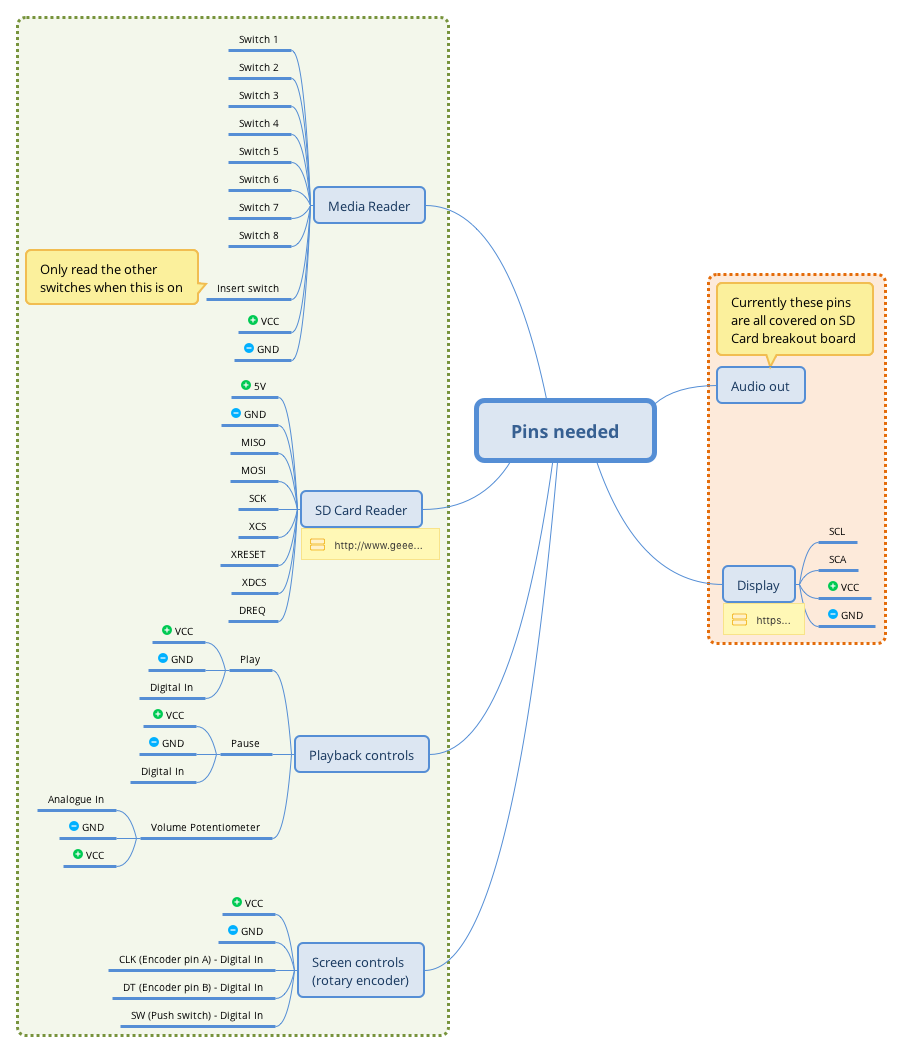
I’ve started mapping out the systems needed for my final project.
From this diagram, I’m creating a draft of the pins I’ll need. Im concerned that my device may need a lot of digital inputs to read all the switches, and so I might need to build a workaround like a key matrix or shift register to combine these inputs into a smaller number of pins.
For now, these are the pins I think I’ll need:
Looking the the ATMega32U4, it has a pinout like this:
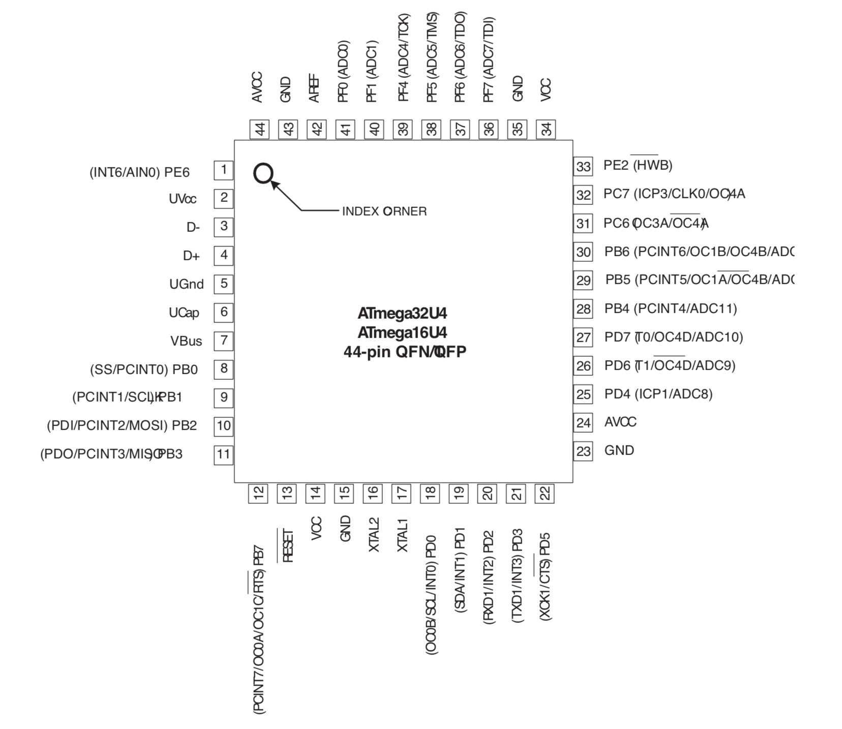
So I can try to map one to the other.
Questions and next steps
- I need to fully spec my final project, so I know exactly what pins I need, and which processor will be suitable
- I need to better understand the libraries needed to drive various parts of my project, e.g. reading data from SD cards, and playing MP3s. This will have an impact on my development approach, especially in how high-level my code will be.
Group assignment
As a group (of mostly non-programmers) we sat down with Michael, who gave us a lesson in Python, and programming the Raspberry Pi.
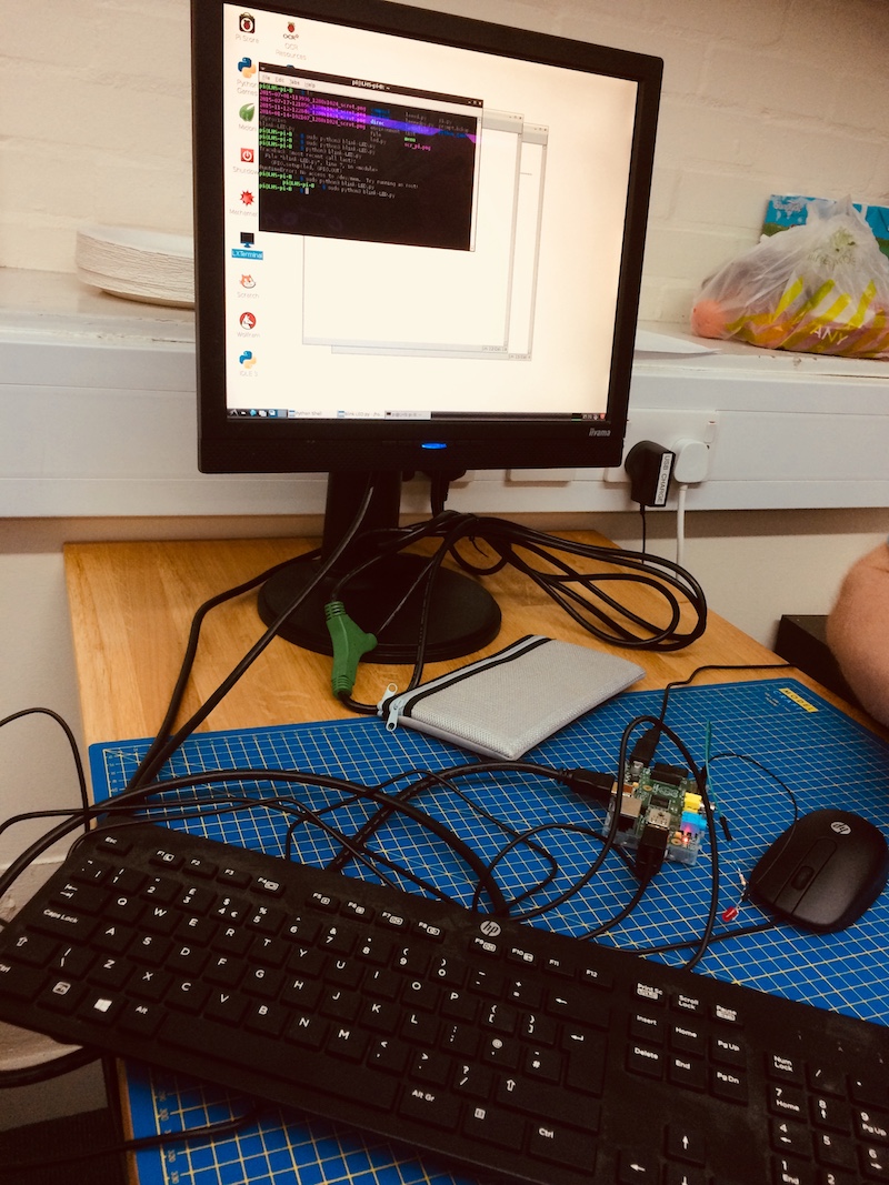
Photo by Derek Covill
We also tried using Python on our own computers and wrote some simple programs like this one:
age = input("How old are you? ")
age = int(age) # convert string to an interger

if age > 40:
    print("You made it!")
elif age < 40:
    print("You don't know you're born")
else:
    print("round number")

    # python uses indenting to tell when you're inside a loop
Our group assignment docs
Embedded programming: Comparing the performance and development workflows for architectures