Week 6 - 3D printing and scanning
Bits to atoms with the 3D printer, and atoms to bits with the 3D scanner
Design a 3D model that couldn’t be fabricated using machines we’ve already covered
I’ve never really printed anything much in a 3D printer, so this is all new territory for me. I figure, as this is a test print, and I’ve never done this before, the model itself isn’t that important.
So I used the built-in object types in Fusion 360 to create a coil about 8cm long, and 3cm diameter. I thought this might have a gentle enough slope that I could print it without support, and if successful, I could get a feel for the mechanical properties of the print: strength, flexibility, springiness, etc.
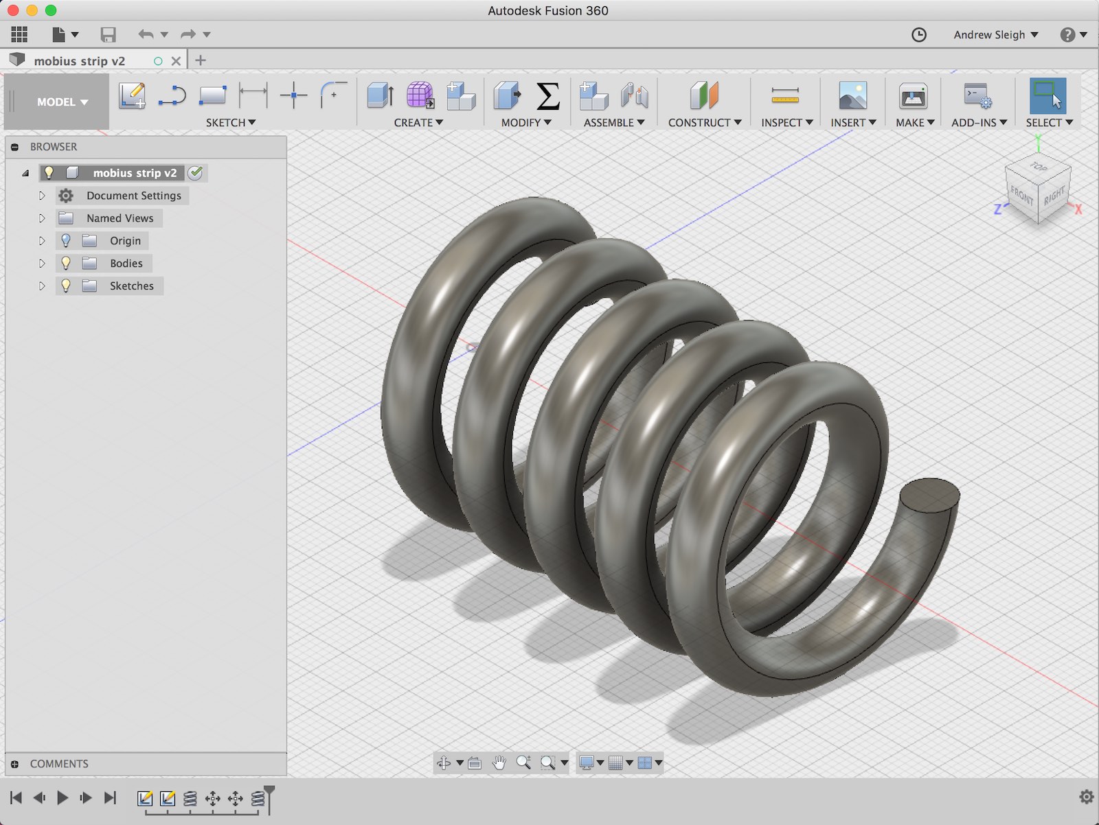
An object like this could not easily be made using subtractive techniques. If you were milling it from a solid block, you’d need a head that could move in all axes, and access the inside of the part. And while it would be technically posible to make it by layering laser cut sheets, almost like contours on a map, this would be a process of manual placement, and the part certainly wouldn’t have any of the mechanical properties of a spring
Then I exported the STL file and opened it in Cura to prepare it for printing.
Group Assignment: documenting the printer
The printer I used is a Creality 3D printer. The lab has documented settings for the printer here:
PDF Export: Instructions for using the CRR10
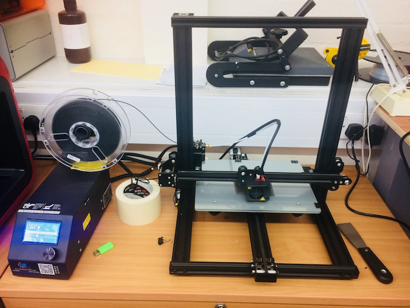
Photo by Derek Covill
This is the CR-10 Mini model, with a build plate of 300mm x 220mm.
Derek also printed some test parts on that printer.
Machine settings
For the first print, I used a 0.6mm nozzle, and printed with PLA.
Layer height: 0.3mm This is about half the diameter of the nozzle. Gives a good speed/quality trade off. A smaller layer height gives higher quality – 0.1mm is lower limit – but slow speeds can be inconveniently slow without much quality difference - maybe even worse as you’re depositing so little material.
Wall thickness: 1.8mm The width of my part is a consistent 6.5mm, and the nozzle is 0.6mm.
Infill: 0% My walls are thick, so I need very litle infill. Usually you’d use more like 20-30%, and if you were going to put the part under pressure or fit a screw in, you’d make this 100%.
Printing temperature: 200°C On the material packaging, they suggest 195-230°C
Build plate: 70°C So that the model will stick to the glass bed. I turned the printer on so the bed could heat to the right temperature before printing.
Diameter: 1.75mm Check the actual material with calipers
Flow: 100% Print speed: 60mm/s Travel speed: 100mm/s Acceleration (Print/travel: 400/4000mm/s2 Cooling: enabled
Support: none Even though this model has overhangs, I want to test printing it without support.
Build plate adhesion: Brim 8mm A ’skirt’ just goes around the part, not in contact. As this model is quite top-heavy, brim seems like a more supportive option.
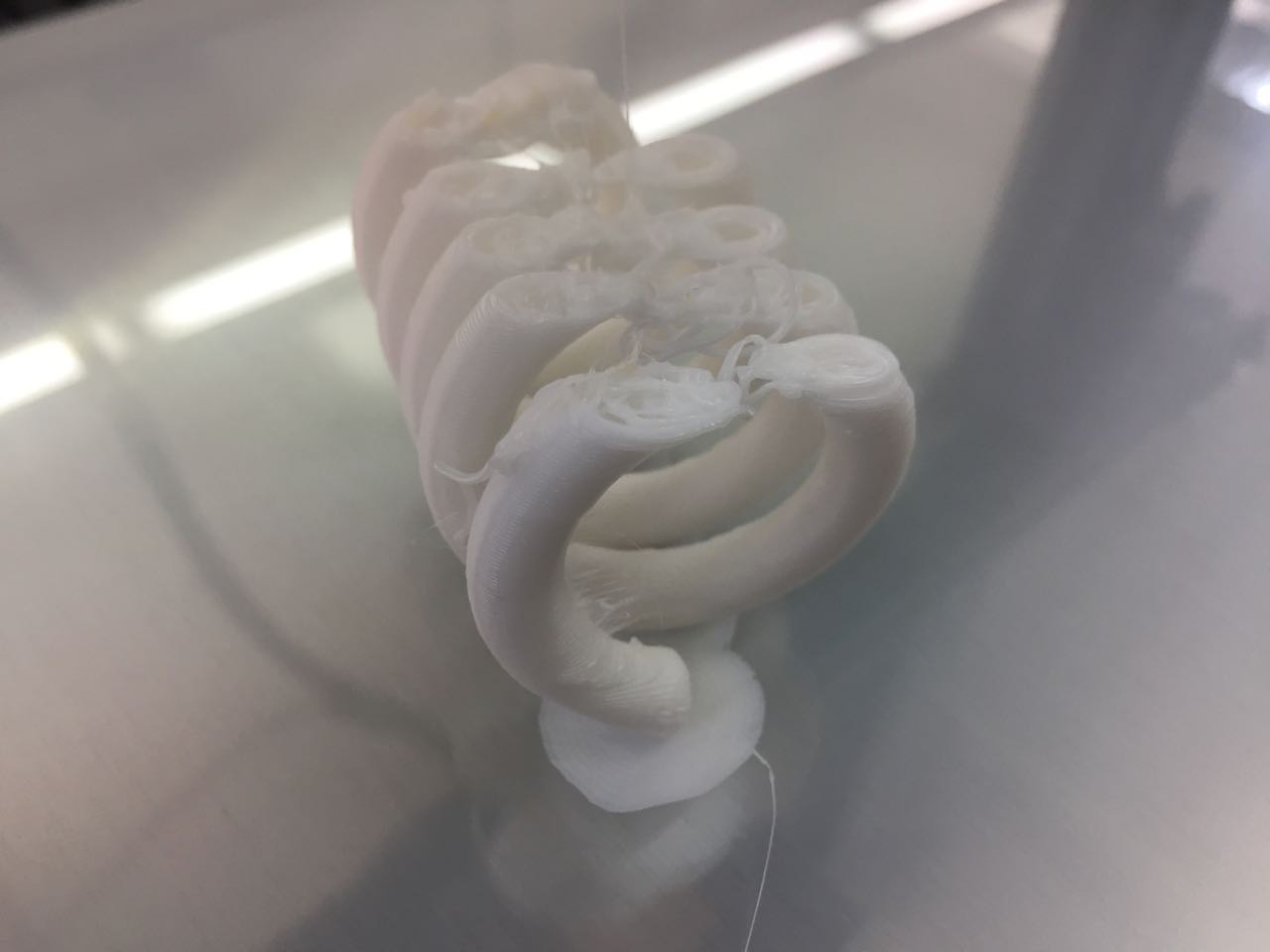
The Result
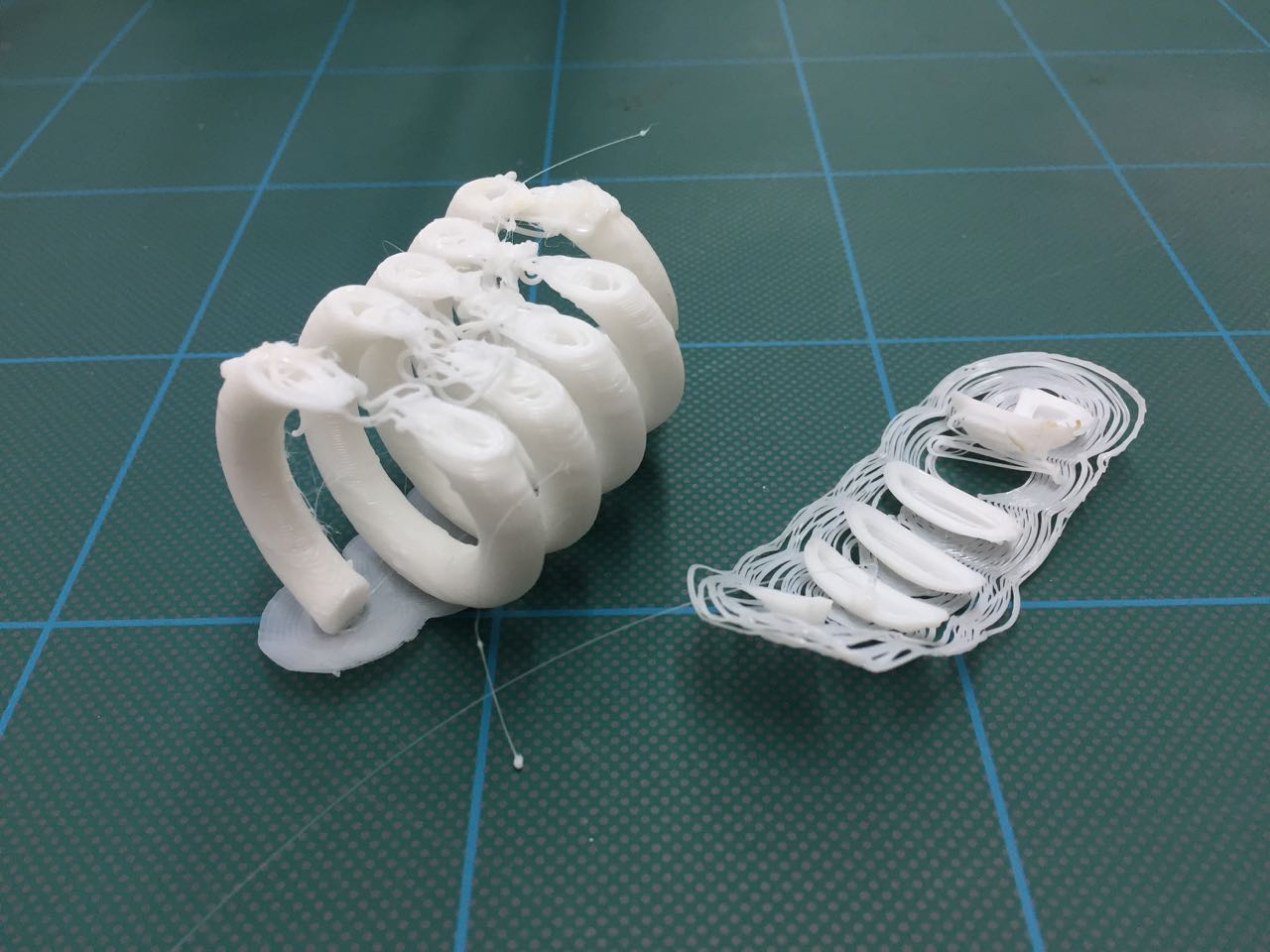
Second Attempt
I set up the machine again with a smaller 0.4mm nozzle, and edited a few of the settings in Cura:
Smaller nozzle size: 0.4mm Lower print temperature: 190°C Larger brim: 12mm
This attempt faired even worse.
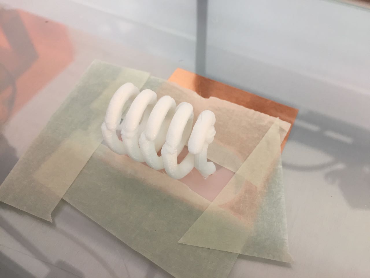
A few weeks later, I tried again, with a smaller model (to save time). And to minimise movement while printing, I taped down the brim with masking tape after the first layer had been printed. This worked better, though there was still some movement part-way thrugh printing:
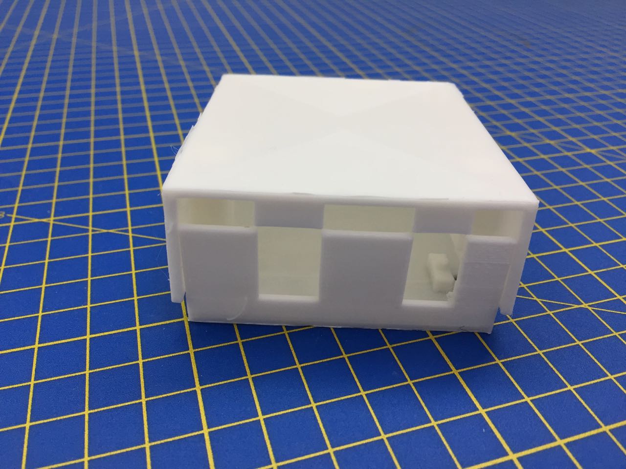
I also tried downloading a model from Thingiverse, that is closer to the sort of thing I might actually need to print for my project. In this case, an Arduino enclosure with mating parts:
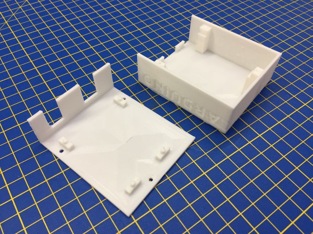
This needs some work to make it viable - the parts don’t currently mate:
Lessons learned
- It’s tricky to print parts with overhangs without using a support structure
- Errors can compound in the printing process: a small wobble in the part can cause subsequent layers to be deposited poorly, increasing irregularities, until the part itself interferes with the print head, causing the whole process to fail
- A brim is a good technique to add stability, especially with the addition of masking tape
- Even a successful print needs lots of finishing to make a viable part if there’s any kind of interaction,
- Digital models and print settings need to be tuned together to get the best print out of a particular model
3D scan an object
I’ve had a small amount of time to play with 3D scanning techniques. Previously I’ve tried using photogrammetry to create 3D models from photos.
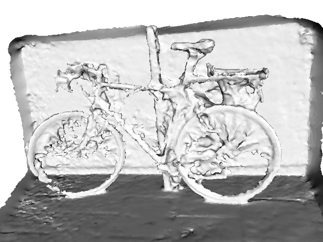
Here’s a bike I found on the street – in retrospect, this was an incredibly challenging thing to scan - with so many voids!
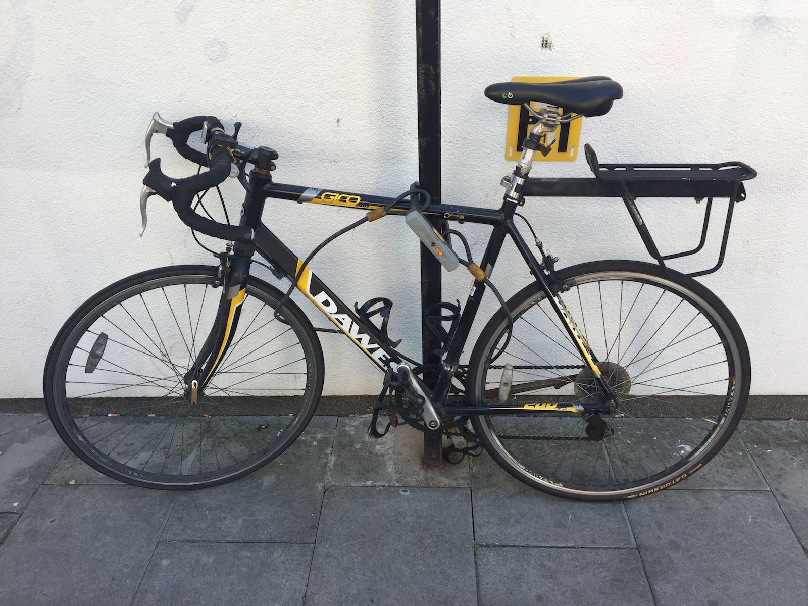
I took 50 photos, and used Agisoft Photoscan to stitch together the images into a 3D model.
I also tried using the iPad-mounted Occipital Structure scanner to try and scan an object in the lab: a set of ratchet crimpers.
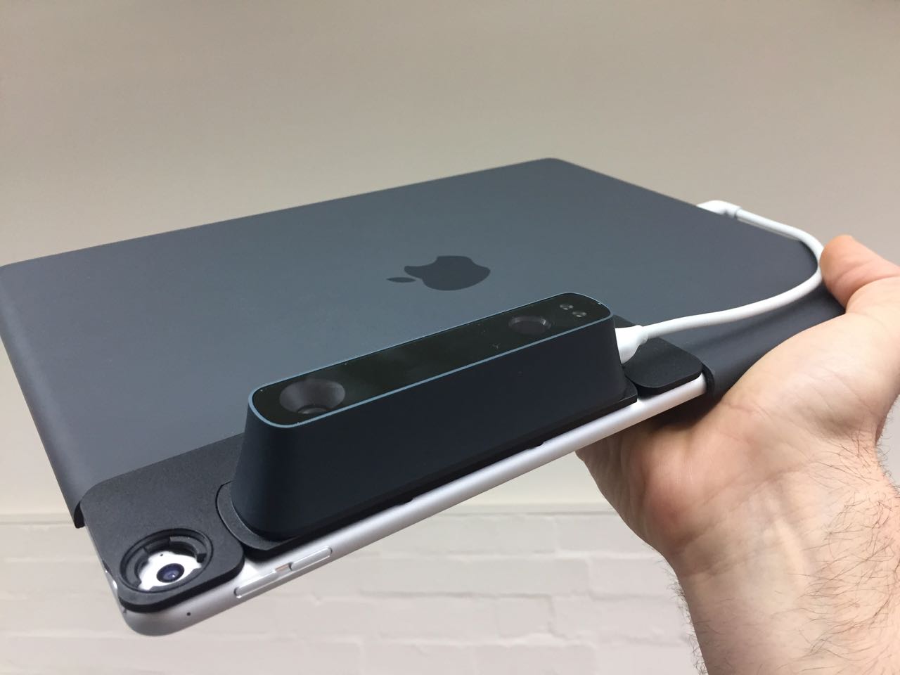
This is my first attempt.
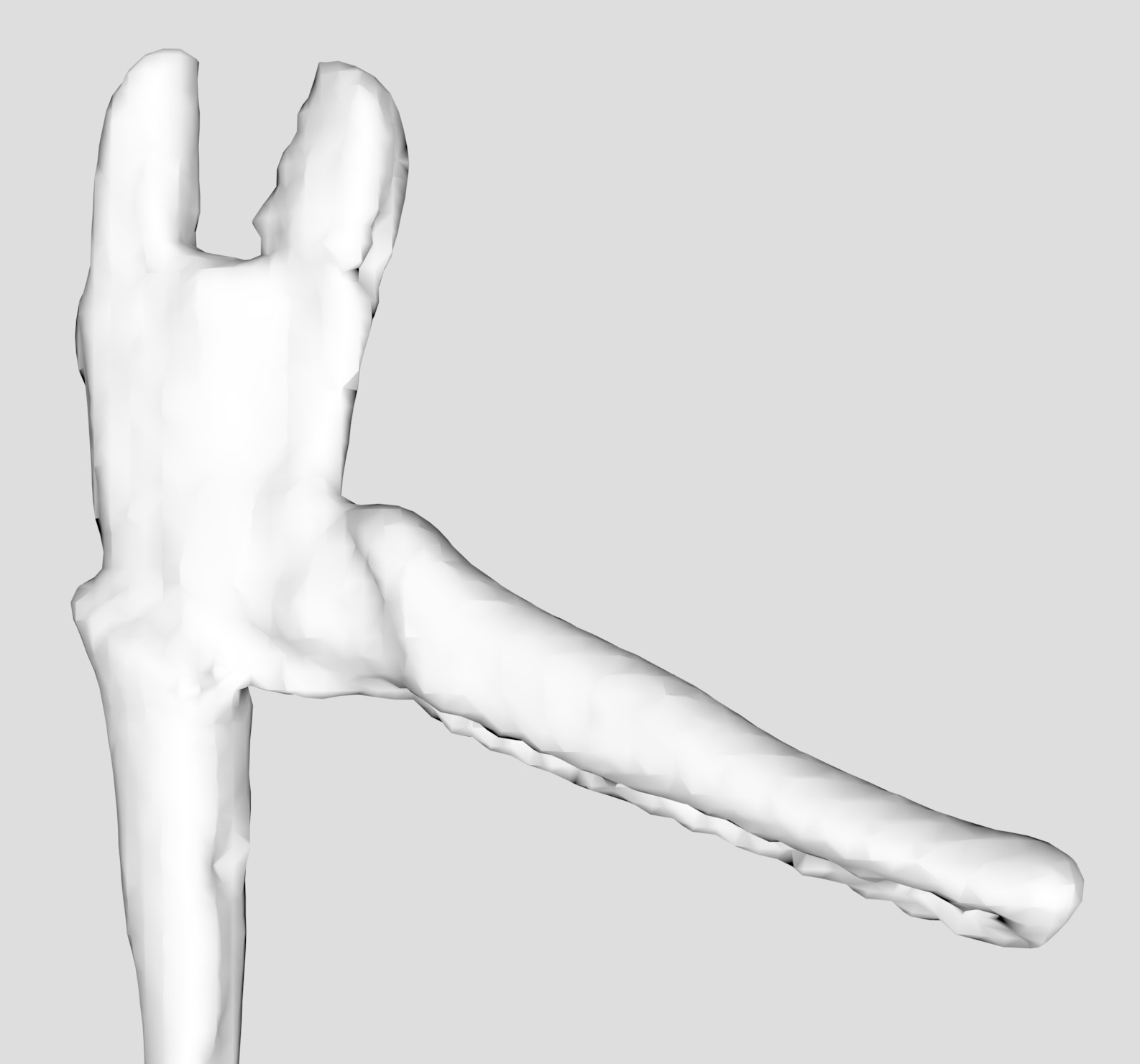
The quality is not good, so I reviewed the documentation to see if I could get a better result
“Ready, fire, aim!”
I made some changes based on what I’d learned from the docs to get a better result:
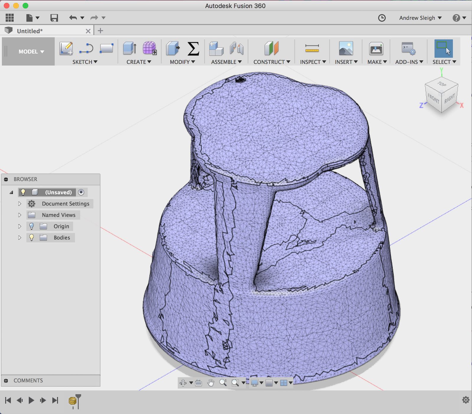
- I tried scanning something simpler and larger – a footstool
- I cleared the viewing area of the scanner and used a large flat surface to give the cleanest view of the object
- I used the preview on the iPad screen to identify areas where I had a good scan, or where parts were missing
- I adjusted the size of the scanning area to fill it as much as possible with the object I was scanning, for higher resolution
I got a better result this time.
Files
3D Printing
Scanning