Week 5 – Making a PCB
This week, we’re using the milling machine (a Roland MDX-50) to mill circuit boards and then solder on components
Group Assignment: Documenting the MDX-50
In the lab we’re collaboratively writing a Google Doc with instructions for all the machines, along with notes on things we’ve learned along the way.
PDF Export: Electronics Production
Milling the PCB
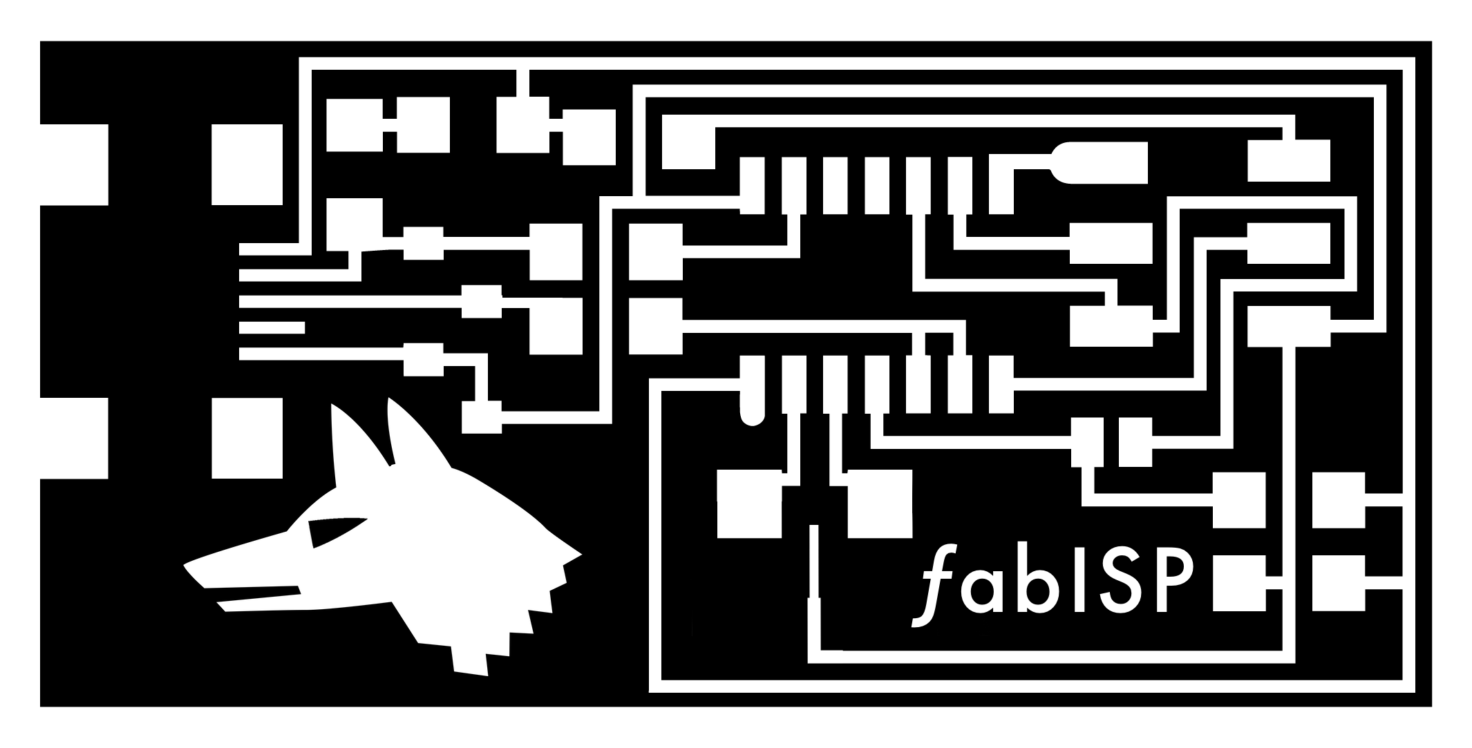
Customising my board
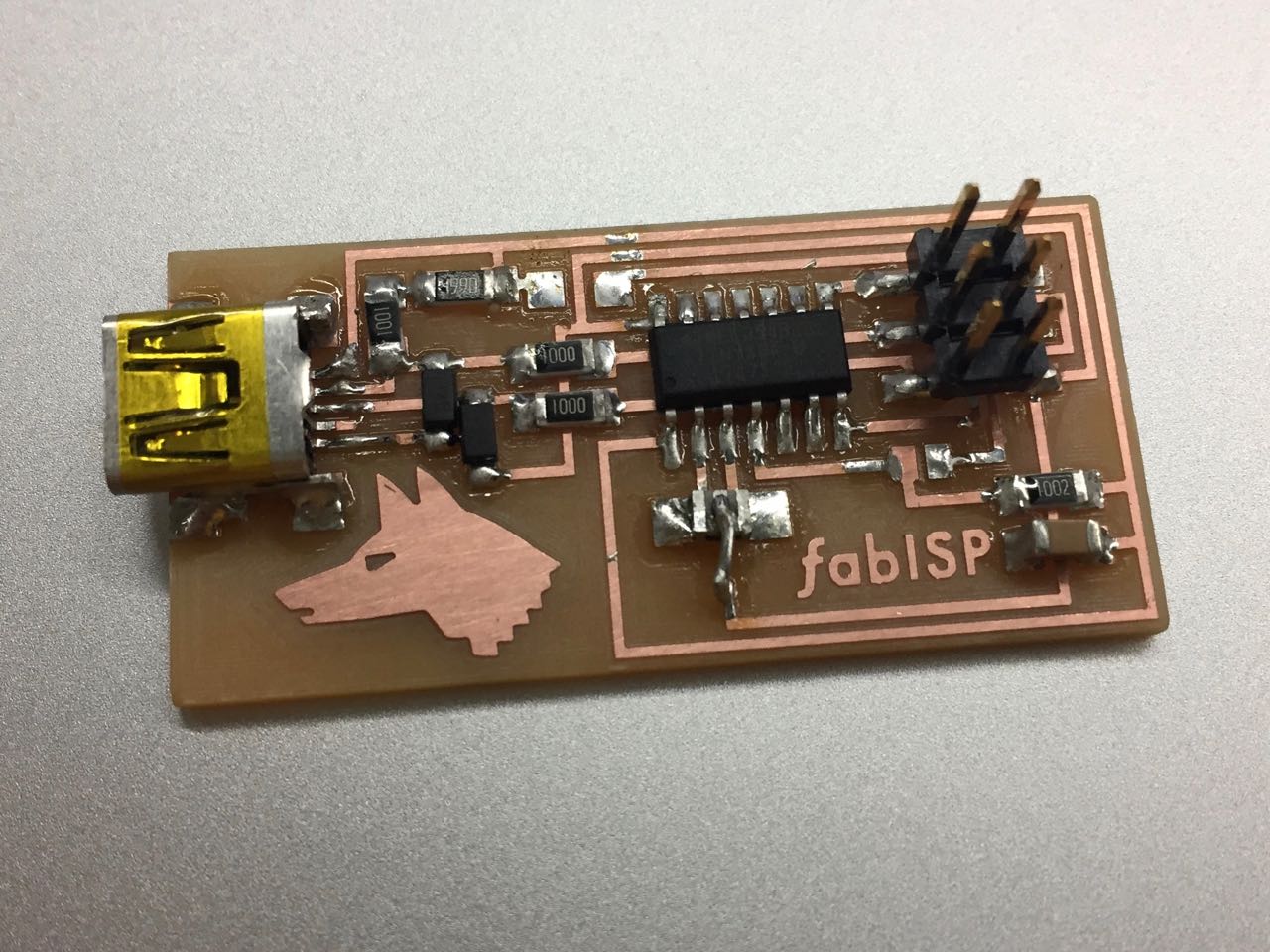
I used an existing circuit design Luiz provided, which we customised with out own logos. I used my Kibbo Kift dog logo.
I also made some adjustments to the PNG to solve some problems with the original, where traces had bridged because they were too close together.
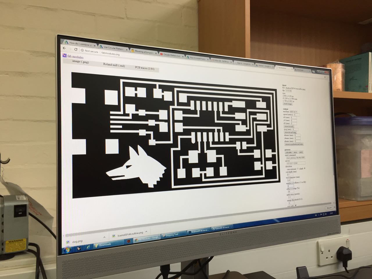
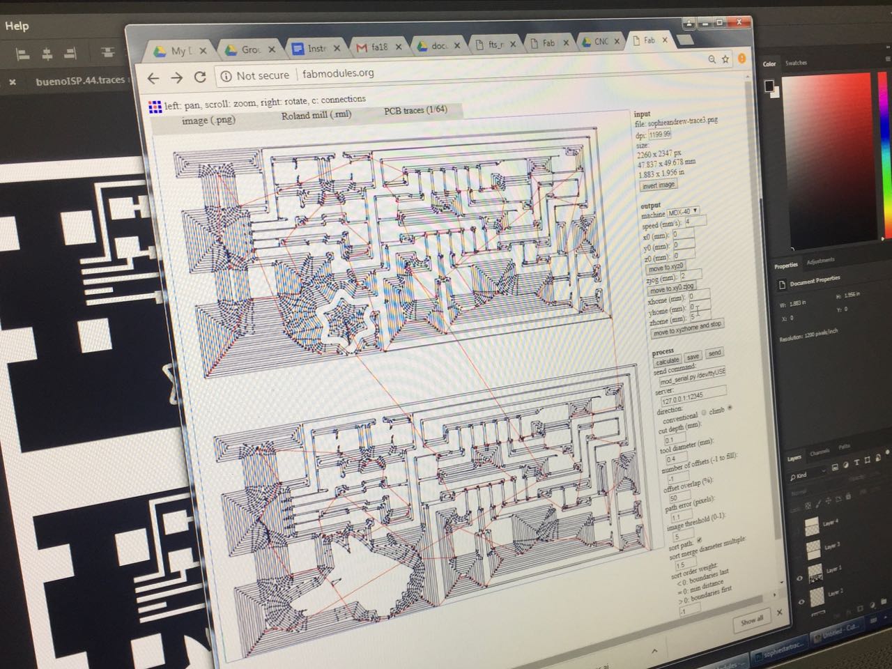
I exported the file as a 1000dpi PNG, and imported it into the Fab Modules software, to generate a cutting file.
Workaround for fine detail
My dog logo has some fine detail, such as the mouth and eye, and the software doesn’t think our 0.4mm bit can get in there to mill out those areas without damaging the ‘traces’ (in reality, just the dog head artwork).
So I changed the settings to say that we were using a finer, 0.3mm tool, and re-calculated the paths. Now the preview shows that the tool will go into these areas to mill them out.
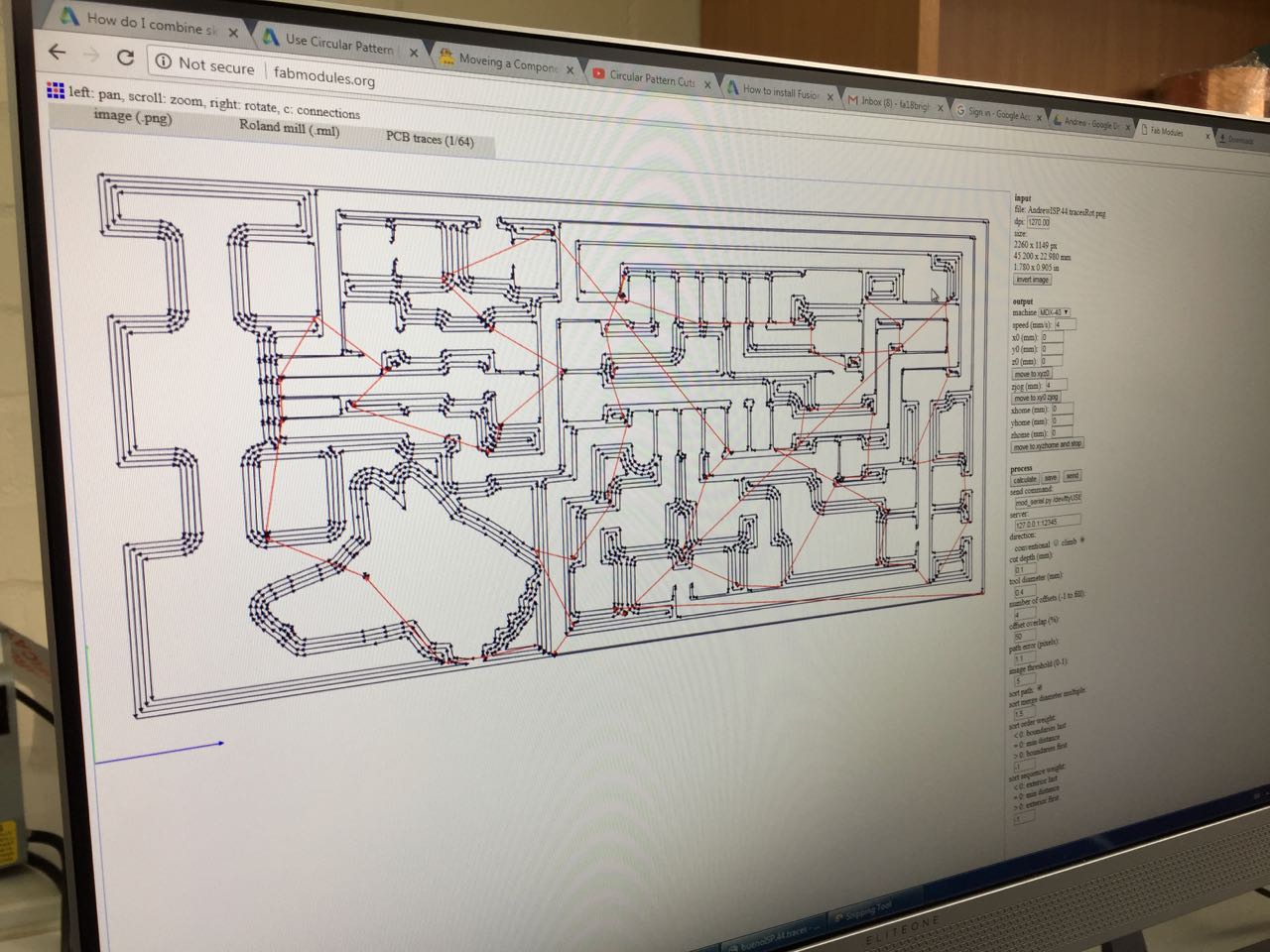
However, there is a downside, which is that the machine will now mill slightly more material out than planned (every path will actually be 0.4mm not 0.3mm – we’re lying to the machine!)
Let’s see how it goes!
User error
The traces cut well, so I loaded up the next PNG for the cutting outline, swapped tools and sent this to the machine. However, my PNG was in the wrong orientation, so instead of cutting around the outside of the board, it started cutting 90° off-axis. Fortunately the first 2 lines were still in the right place, and I managed to catch it before it did any damage. All caught on film:
I regenerated a new RML file in the correct orientation, and was able to cut again without changing anything on the machine. A very lucky mistake!
It all cut fine in the end.
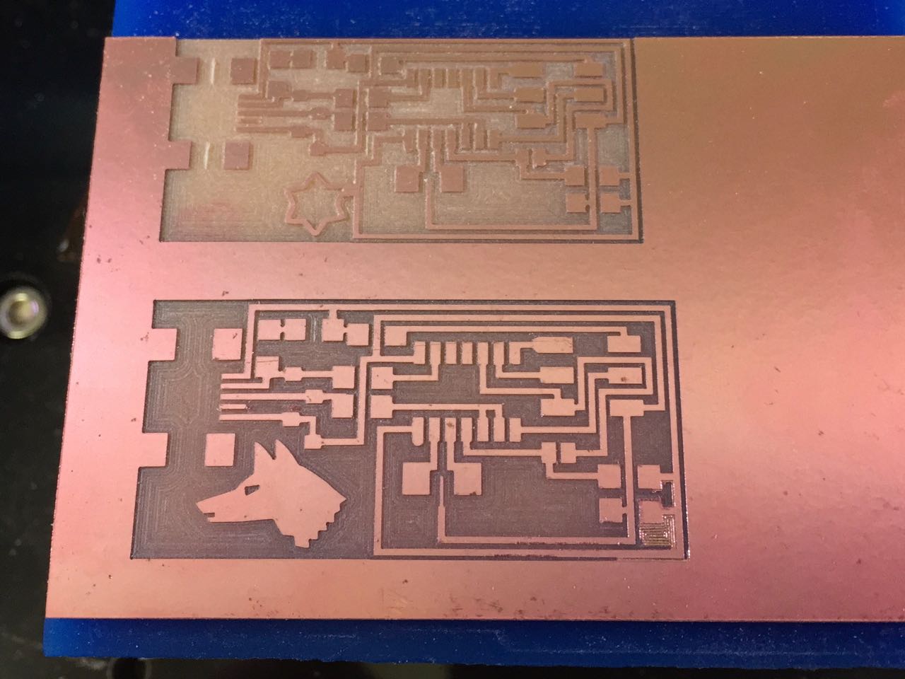
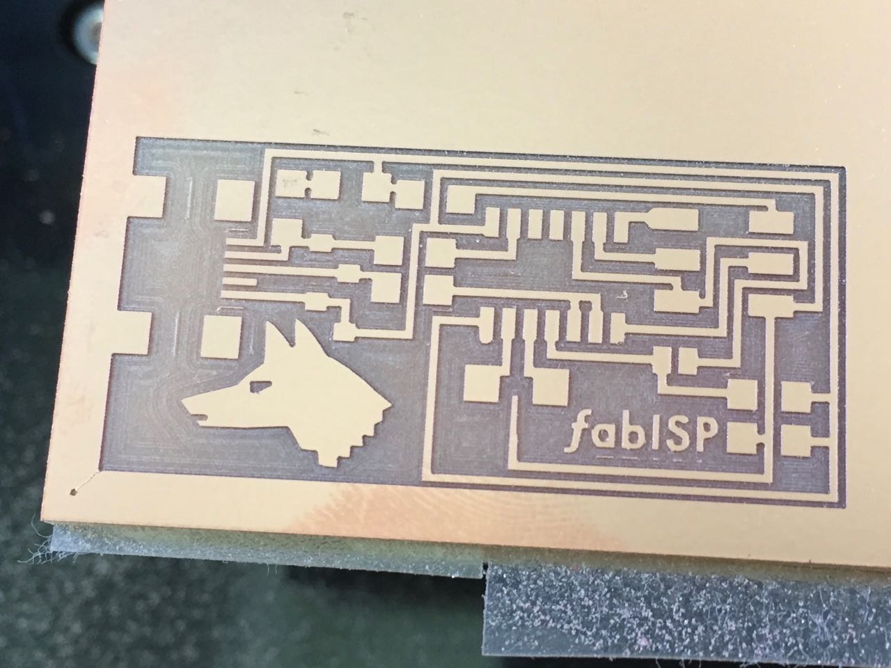
Checking the result
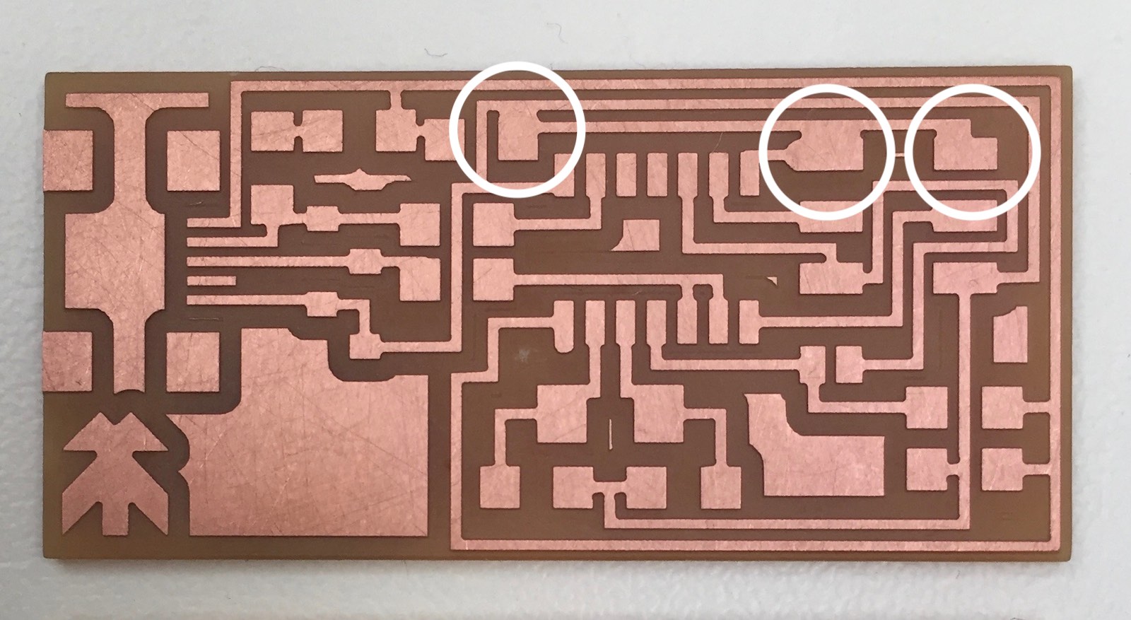
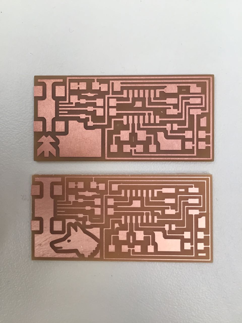
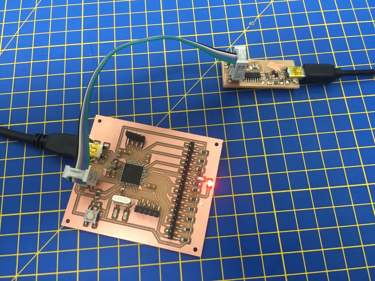
The board looks great, but the traces are certainly thin, relative to the original board (mine is the lower of the two boards in this picture) I can test it with a multimeter to verify the paths.
I plan to change the artwork slightly to make the dog detail easier to cut, without having to use the fake tool size workaround.
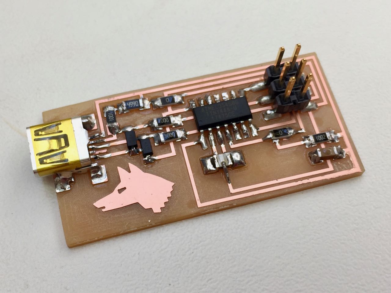
Soldering the components
There were some problems with the design of the original boards we milled, so we milled new boards.
The lab is also not yet full stocked with the correct components, so we had to solder a mix of SMD and through-hole components.
That meant drilling some holes in the board for the through-hole components. After doing this, and strippin away some of the excess copper with a craft knife, I soldered the SMD parts first.
The header and chip were fine, I used the tacking method to secure one corner of each piece first, then going round and soldering proper joins on all the pins. I’d say about 50% of my joins flowed nicely.
But the second LED was even smaller than the first. When I attached this, I bridged two traces with solder, which I couldn’t remove with the braid. I decided to remove the LED completely, and then remove the solder. In the process I broke the LED, but fortunately had a spare in the larger size.
After the SMD components, I moved onto the through-hole, which I actually found slightly harder. They moved around when soldering, and even my smallest drill bit made holes that were too large, so the solder didn’t easily flow.
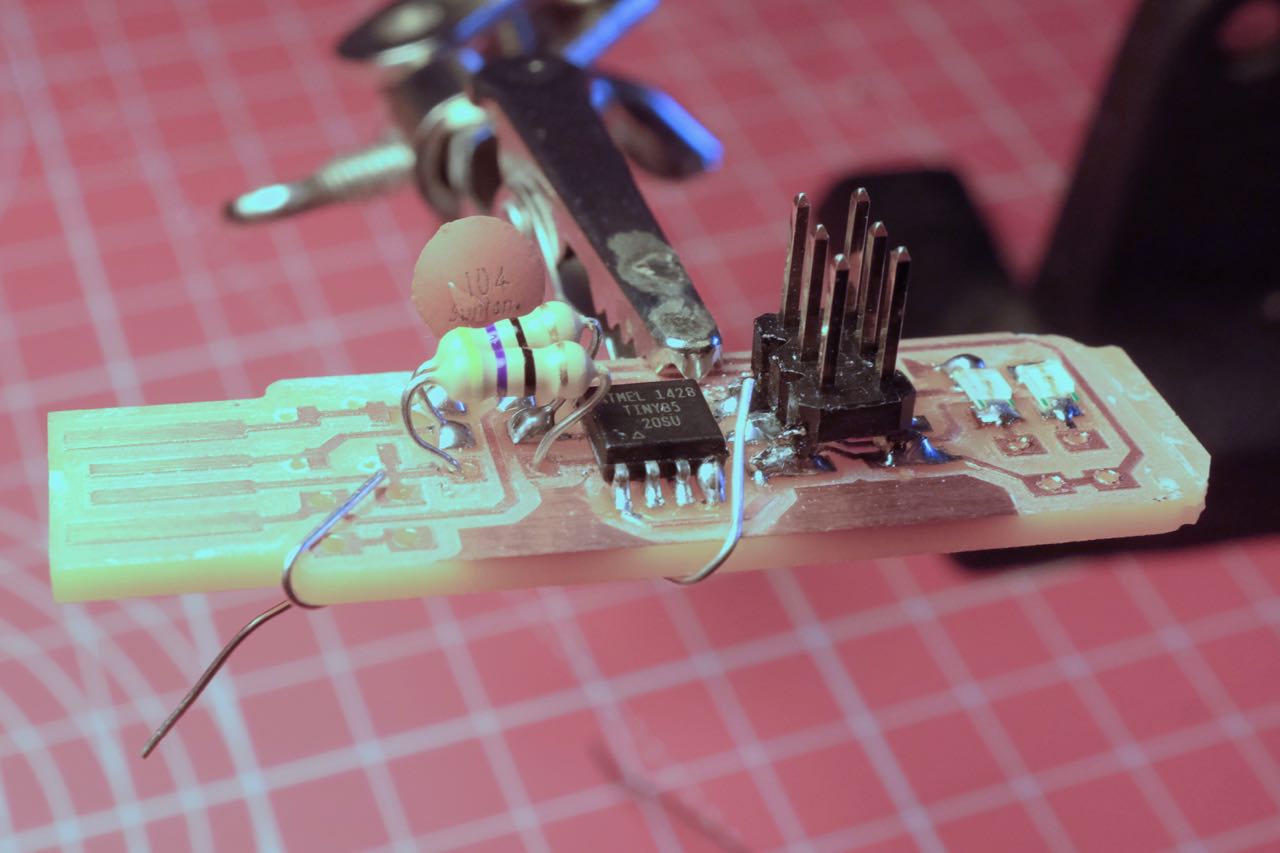
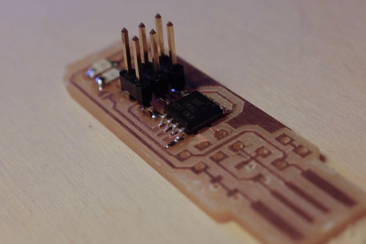
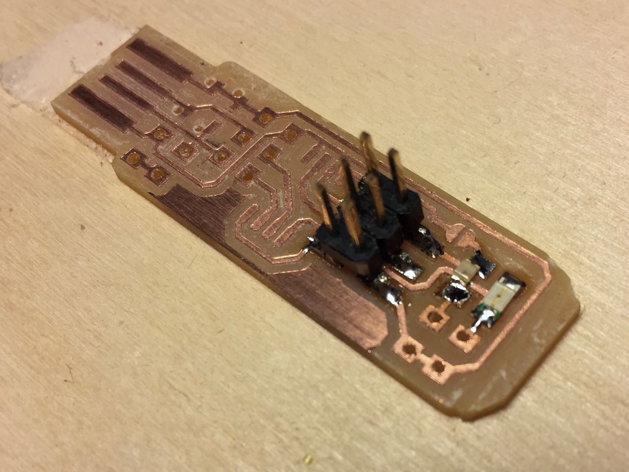
And the finished result:
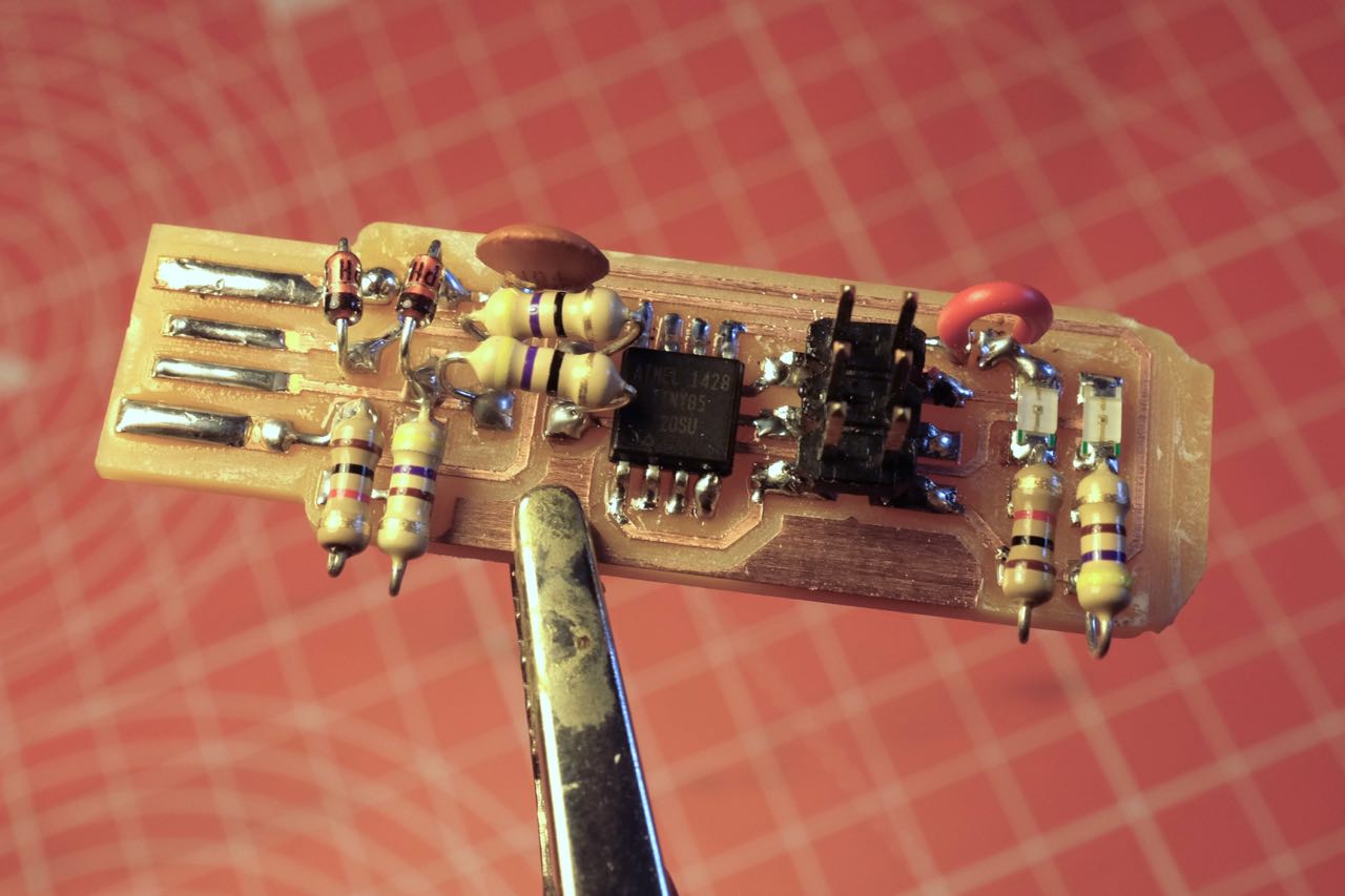
Programming the board
I followed these instructions
Download and install CrossPack.
Get and build the Firmware
Download the firmware source code and extract the zip file (on Linux, unzip fts_firmware_bdm_v1.zip). Open your terminal program and cd into the source code directory. Run make. This will build the hex file that will get programmed onto the ATtiny45. When the command completes, you should now have a file called fts_firmware.hex. If the command doesn’t complete successfully, something is wrong with your toolchain installation. Consult the error messages for information that will help you debug it.”
Program the ATtiny45
I made a mistake editing the Makefile:
MCU = attiny45
PROGRAMMER ?= usbtiny
F_CPU = 16500000UL
I skipped past the step to change the MCU. Mine is an attiny85, not attiny45
When I ran make flash, I got an error. So I ran make clean in Terminal to clear the old files I had generated, changed the line in the Makefile, and the make again.
I fixed the MCU line, then ran make flash again.
This will erase the target chip, and program its flash memory with the contents of the .hex file you built before. You should see several progress bars while avrdude erases, programs, and verifies the chip. Once you’ve succesfully programmed the flash memory, it’s time to set the configuration fuses. Run the make fuses command. This will set up all of the fuses except the one that disables the reset pin. Again, you should see several progress bars from avrdude.
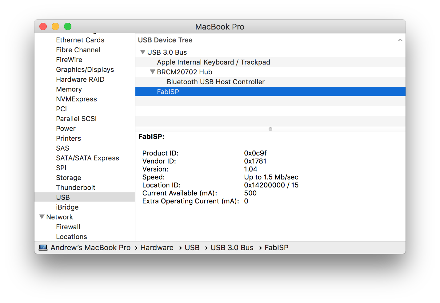
Test the USB Functionality
I checked the USB devices on my Mac, and it showed up successfully:

Blow the Reset Fuse
First, we need to change the bit that will turn the ATtiny45’s reset pin into a GPIO pin. Connect your ISP programmer to your board one more time, and run make rstdisbl
My board failed at this stage with this error:
avrdude -p attiny85 -c usbtiny -P usb \
		-U lfuse:w:0xE1:m -U hfuse:w:0x5D:m \
		-U efuse:w:0xFF:m

avrdude: initialization failed, rc=-1
         Double check connections and try again, or use -F to override
         this check.


avrdude done.  Thank you.

make: *** [rstdisbl] Error 1
This could be due to poor connections or shorts. But I will probably fab another board, now that we have all the SMD components in the lab, and it will give me an opportunity to practice my soldering.
Second board
I milled a second board based on the ATTiny 44 chip, to get more practice on the millling machine and soldering SMD components
Milling the board
I set up the board 2-up with another student’s board in Fab Modules so we could mill both at the same time.
You can see from this screen that my board is slightly too large. I don’t know how this happened, as my workflow from original PNG to my customised version was very straightforward. I milled and soldered it anyway, and it seemed to be pretty much OK, though the spacing on some of the pins was noticeably out.
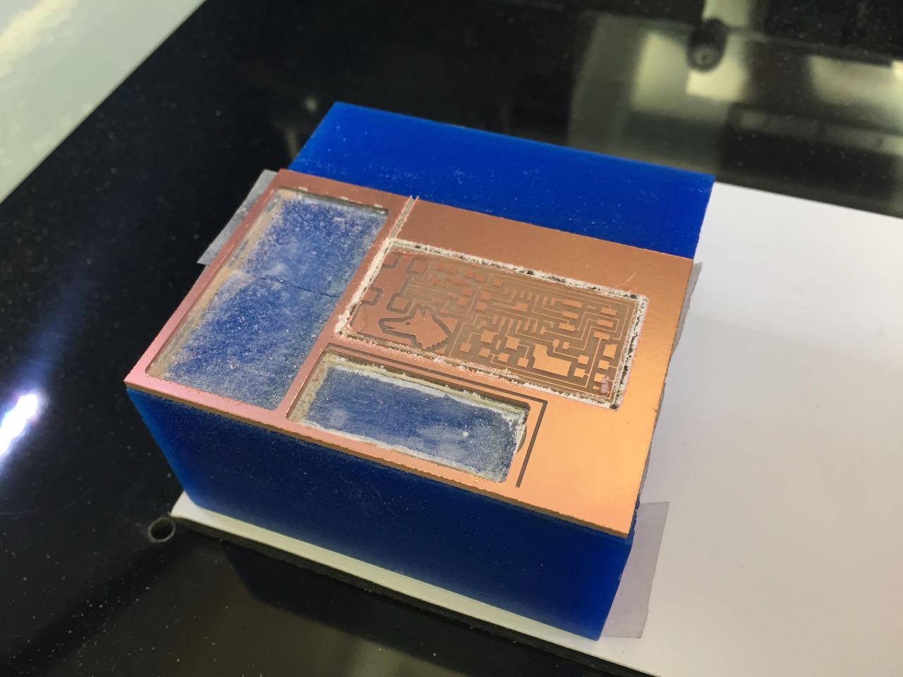
We used the ‘-1’ offset setting to remove all the unwanted material. You can see on this board that not all the material was removed at the lower right corner. I think this was due to the board being slightly warped, and not sticking to the sacrificial base properly.
When I got home, I was able to get a closer look at this region under the microscope.
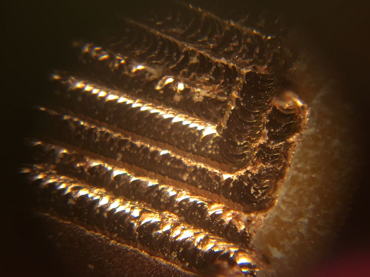
I used a craft knife to remove the excess copper.
Soldering the board
This time, all the components are SMD. Now I need to programe and verify it.
## Programming the board
This time, I followed the instructions here for the ATTiny44.
Download the firmware
From http://academy.cba.mit.edu/classes/embedded_programming/firmware.zip Unzip, and move into that directory in Terminal
Edit the Makefile
I edited the config lines like so:
DEVICE  = attiny44
#F_CPU   = 12000000	# edit this line for crystal speed, in Hz
F_CPU   = 20000000	# edit this line for crystal speed, in Hz
FUSE_L  = 0xFF
FUSE_H  = 0xDF
AVRDUDE = avrdude -c usbtiny -p $(DEVICE) # edit this line for your programmer
#AVRDUDE = avrdude -c avrisp2 -P usb -p $(DEVICE) # edit this line for your programmer
Compile the firmware
By running make clean followed by make hex. My result:
Andrews-MBP:fabISP_mac.0.8.2_firmware andrew$ make clean
rm -f main.hex main.lst main.obj main.cof main.list main.map main.eep.hex main.elf *.o usbdrv/*.o main.s usbdrv/oddebug.s usbdrv/usbdrv.s
Andrews-MBP:fabISP_mac.0.8.2_firmware andrew$ make hex
avr-gcc -Wall -Os -DF_CPU=20000000	 -Iusbdrv -I. -DDEBUG_LEVEL=0 -mmcu=attiny44 -c usbdrv/usbdrv.c -o usbdrv/usbdrv.o
avr-gcc -Wall -Os -DF_CPU=20000000	 -Iusbdrv -I. -DDEBUG_LEVEL=0 -mmcu=attiny44 -x assembler-with-cpp -c usbdrv/usbdrvasm.S -o usbdrv/usbdrvasm.o
avr-gcc -Wall -Os -DF_CPU=20000000	 -Iusbdrv -I. -DDEBUG_LEVEL=0 -mmcu=attiny44 -c usbdrv/oddebug.c -o usbdrv/oddebug.o
avr-gcc -Wall -Os -DF_CPU=20000000	 -Iusbdrv -I. -DDEBUG_LEVEL=0 -mmcu=attiny44 -c main.c -o main.o
main.c:88:13: warning: always_inline function might not be inlinable [-Wattributes]
 static void delay ( void )
             ^
avr-gcc -Wall -Os -DF_CPU=20000000	 -Iusbdrv -I. -DDEBUG_LEVEL=0 -mmcu=attiny44 -o main.elf usbdrv/usbdrv.o usbdrv/usbdrvasm.o usbdrv/oddebug.o main.o
rm -f main.hex main.eep.hex
avr-objcopy -j .text -j .data -O ihex main.elf main.hex
avr-size main.hex
   text	   data	    bss	    dec	    hex	filename
      0	   2002	      0	   2002	    7d2	main.hex
Set the fuses
By running make fuse. My result:
Andrews-MBP:fabISP_mac.0.8.2_firmware andrew$ make fuse
avrdude -c avrisp2 -P usb -p attiny44  -U hfuse:w:0xDF:m -U lfuse:w:0xFF:m
avrdude: usbdev_open(): did not find any USB device "usb"
make: *** [fuse] Error 1
I checked the traces on both boards with my multimeter, and found a short on my resonator, so we removed it and resoldered it on the board.
### Start again
Run make clean followed by make hex. Same warning in the result:
main.c:88:13: warning: always_inline function might not be inlinable [-Wattributes]
 static void delay ( void )
             ^
So I desoldered that resonator, and replaced it. This time it worked:
Andrews-MBP:fabISP_mac.0.8.2_firmware andrew$ make fuse
avrdude -c usbtiny -p attiny44  -U hfuse:w:0xDF:m -U lfuse:w:0xFF:m

avrdude: AVR device initialized and ready to accept instructions

Reading | ################################################## | 100% 0.00s

avrdude: Device signature = 0x1e9207
avrdude: reading input file "0xDF"
avrdude: writing hfuse (1 bytes):

Writing | ################################################## | 100% 0.00s

avrdude: 1 bytes of hfuse written
avrdude: verifying hfuse memory against 0xDF:
avrdude: load data hfuse data from input file 0xDF:
avrdude: input file 0xDF contains 1 bytes
avrdude: reading on-chip hfuse data:

Reading | ################################################## | 100% 0.00s

avrdude: verifying ...
avrdude: 1 bytes of hfuse verified
avrdude: reading input file "0xFF"
avrdude: writing lfuse (1 bytes):

Writing | ################################################## | 100% 0.00s

avrdude: 1 bytes of lfuse written
avrdude: verifying lfuse memory against 0xFF:
avrdude: load data lfuse data from input file 0xFF:
avrdude: input file 0xFF contains 1 bytes
avrdude: reading on-chip lfuse data:

Reading | ################################################## | 100% 0.00s

avrdude: verifying ...
avrdude: 1 bytes of lfuse verified

avrdude: safemode: Fuses OK (H:FF, E:DF, L:FF)

avrdude done.  Thank you.
Next step: make program. My result:
Andrews-MBP:fabISP_mac.0.8.2_firmware andrew$ make program
avrdude -c usbtiny -p attiny44  -U flash:w:main.hex:i

avrdude: AVR device initialized and ready to accept instructions

Reading | ################################################## | 100% 0.00s

avrdude: Device signature = 0x1e9207
avrdude: NOTE: "flash" memory has been specified, an erase cycle will be performed
         To disable this feature, specify the -D option.
avrdude: erasing chip
avrdude: reading input file "main.hex"
avrdude: writing flash (2002 bytes):

Writing | ################################################## | 100% 1.82s

avrdude: 2002 bytes of flash written
avrdude: verifying flash memory against main.hex:
avrdude: load data flash data from input file main.hex:
avrdude: input file main.hex contains 2002 bytes
avrdude: reading on-chip flash data:

Reading | ################################################## | 100% 2.35s

avrdude: verifying ...
avrdude: 2002 bytes of flash verified

avrdude: safemode: Fuses OK (H:FF, E:DF, L:FF)

avrdude done.  Thank you.

avrdude -c usbtiny -p attiny44  -U hfuse:w:0xDF:m -U lfuse:w:0xFF:m

avrdude: AVR device initialized and ready to accept instructions

Reading | ################################################## | 100% 0.00s

avrdude: Device signature = 0x1e9207
avrdude: reading input file "0xDF"
avrdude: writing hfuse (1 bytes):

Writing | ################################################## | 100% 0.00s

avrdude: 1 bytes of hfuse written
avrdude: verifying hfuse memory against 0xDF:
avrdude: load data hfuse data from input file 0xDF:
avrdude: input file 0xDF contains 1 bytes
avrdude: reading on-chip hfuse data:

Reading | ################################################## | 100% 0.00s

avrdude: verifying ...
avrdude: 1 bytes of hfuse verified
avrdude: reading input file "0xFF"
avrdude: writing lfuse (1 bytes):

Writing | ################################################## | 100% 0.00s

avrdude: 1 bytes of lfuse written
avrdude: verifying lfuse memory against 0xFF:
avrdude: load data lfuse data from input file 0xFF:
avrdude: input file 0xFF contains 1 bytes
avrdude: reading on-chip lfuse data:

Reading | ################################################## | 100% 0.00s

avrdude: verifying ...
avrdude: 1 bytes of lfuse verified

avrdude: safemode: Fuses OK (H:FF, E:DF, L:FF)

avrdude done.  Thank you.
Here’s my board listed as a USB device:
However, when it came to program my Hello World board, this programmer didn’t work. SO I started again:
Third attempt
I used the original board design, but looked into the resizing problems, which I think were being caused by PNGs being exported at different resolutions. So I measured my PNG and verified it against actual components before generating my cutting paths.
Traces bitmap
Milled board
Soldered board
You can see that I had some problems with the resonator. The central trace going to the GND point of the resonator peeled off the board, so I had to use a small piece of wire to create a bridge to the component. Ugly, but I verified with the multimeter that it works and caused no shorts.
I ran the programmer code, removed the 2 0Ohm resistors, and used this programmer to program my Hello World Board in week 7
I also used it to program later boards including my input devices and output devices boards (input devices board pictured below)